1
Nova M3 LED Display Control System User Manual H C R A O C ., D T L TE T S A V N A O N ' I X This information could include technical inaccuracies or typographical errors. Changes are periodically made to the information herein; these changes will be incorporated in new editions of the publication. Nova may make improvements and/or changes in the product(s) and/or the program(s) described in this publication at any time without notice. Copyright © 2012 by Xi’anNovaStar Technology Company Limited. All right reserved. Xi’an NovaStar Tech Co., LTD NovaStar Tech Co.Ltd Content 1 INTRODUCTION TONOVALCT-MARS ...................................................................................................................... 1 1.1 CONFIGURATION LIST ................................................................................................................................................. 3 1.2 SYSTEM ARCHITECTURE............................................................................................................................................... 4 2 WORKING ENVIRONMENT REQUIREMENTS .......................................................................................................... 4 3 INSTALLATION OF NOVALCT-MARS ....................................................................................................................... 5 4 MAIN INTERFACE OF NOVALCT-MARS ................................................................................................................... 6 5 ., D T L 4.1 UPDATE PASSWORD ................................................................................................................................................... 7 4.2 MAIN MENU............................................................................................................................................................ 7 4.3 TOOL BAR .............................................................................................................................................................. 11 H C O C TE MAIN FUNCTIONS OF NOVALCT-MARS ................................................................................................................11 5.1 START THE LED DISPLAYS .......................................................................................................................................... 12 R A 5.1.1 Start with System Configuration Files ............................................................................................................ 12 5.1.2 Start Manually ............................................................................................................................................... 13 5.1.3 Set the Cabinet Info ........................................................................................................................................ 37 5.1.4 Adjust the Performance Parameters .............................................................................................................. 39 5.1.5 Adjust the Resolution and Refresh Rate ......................................................................................................... 50 5.1.6 3D Config........................................................................................................................................................ 53 T S A V N A O N ' I X 5.1.7 Set Hot Backup for Receiver Cards ................................................................................................................. 54 5.1.8 HDMI Settings(MSD600/MCTRL600/MCTRL610) ..................................................................................... 57 5.1.9 Save Settings to FLASH ................................................................................................................................... 57 5.1.10 5.2 Save/Load Configuration Files ................................................................................................................... 58 ADJUST THE BRIGHTNESS, DISPLAY QUALITY, GAMMA AND CURRENT GAIN.......................................................................... 62 5.2.1 Manual Adjustment ....................................................................................................................................... 62 5.2.2 Schedule Adjustment...................................................................................................................................... 65 5.2.3 Auto................................................................................................................................................................ 67 5.2.4 Auto Adjustment By Hardware ...................................................................................................................... 74 Phone: NovaStar (Xi’an) 86-29-84507048NovaStar (Shenzhen) 86-755-33592492 Website: www.novastar-led.com II NovaStar Tech Co.Ltd 5.3 DISPLAY CONTROL ................................................................................................................................................... 77 5.4 CHECK HARDWARE INFO ........................................................................................................................................... 78 5.5 MANAGE THE LED DISPLAYS ..................................................................................................................................... 79 5.6 MONITOR THE SYSTEM ............................................................................................................................................. 83 5.6.1 Monitor Setting .............................................................................................................................................. 86 5.6.2 Email Notification Setting .............................................................................................................................. 90 5.6.3 Notification Email Log .................................................................................................................................... 91 5.6.4 Monitor-Control ............................................................................................................................................. 92 D T L 5.7 ERROR DOT DETECT ................................................................................................................................................ 96 5.8 BRIGHTNESS/COLOR CALIBRATION............................................................................................................................ 101 O C ., 5.8.1 Online Calibration ........................................................................................................................................ 101 5.8.2 Manage Coefficients .................................................................................................................................... 103 5.8.3 Reset coefficients ......................................................................................................................................... 130 5.9 H C TE FUNCTION CARD MANAGEMENT .............................................................................................................................. 131 R A 5.9.1 Function Card Configuration ........................................................................................................................ 131 5.9.2 Power Management .................................................................................................................................... 132 5.9.3 Monitor Data ............................................................................................................................................... 139 5.9.4 External Device ............................................................................................................................................. 139 5.9.5 Load Program............................................................................................................................................... 140 T S A V O N 5.10 CABINET LIBRARY MANAGEMENT ............................................................................................................................. 142 5.11 PRESTORE PICTURE ................................................................................................................................................ 146 5.12 N A ' I X COLOR RESTORE ................................................................................................................................................... 147 6 MEMORY ON MODULE MANAGE .......................................................................................................................150 7 MULTI BATCH ADJUSTMENT ...............................................................................................................................155 7.1 APPLICATIONS ADJUSTMENT FILE ............................................................................................................................. 155 7.2 MANUAL ADJUSTMENT........................................................................................................................................... 157 8 RECEIVE CARD RELAY .........................................................................................................................................169 9 LOAD CONFIGURATION FILE ...............................................................................................................................170 Phone: NovaStar (Xi’an) 86-29-84507048NovaStar (Shenzhen) 86-755-33592492 Website: www.novastar-led.com III NovaStar Tech Co.Ltd 10 CONFIGURE INFORMATION MANAGEMENT ......................................................................................................176 11 HARDWARE PROGRAM UPDATING ....................................................................................................................176 12 DARK OR BRIGHT LINES ADJUSTMENT FOR CABINET .........................................................................................180 13 14 12.1 DARK OR BRIGHT LINES ADJUSTMENT FOR CABINET ..................................................................................................... 180 12.2 DARK OR BRIGHT LINES RECOVERY FOR CABINET ......................................................................................................... 185 PROBLEM AND SOLUTION .................................................................................................................................185 D T L 13.1 NOVALCT-MARS SHOWS “NO HARDWARE” ON CORRESPONDING PAGES. ........................................................................ 185 13.2 NOVALCT-MARS SHOWS “NO SCREEN” ON CORRESPONDING PAGES. ............................................................................. 186 13.3 THE LED DISPLAY DOES NOT SHOW THE IMAGE CORRECTLY DURING THE SMART SETTING PROCEDURE. ................................... 186 13.4 ONLY A PART OF THE MODULES OF EACH CABINET WORK NORMALLY IN SMART SETTING. ..................................................... 187 13.5 PERMISSION ERROR ............................................................................................................................................... 188 H C O C ., TE APPENDIX ..........................................................................................................................................................193 14.1 R A UPDATE INFO ....................................................................................................................................................... 193 T S A V N A O N ' I X Phone: NovaStar (Xi’an) 86-29-84507048NovaStar (Shenzhen) 86-755-33592492 Website: www.novastar-led.com IV NovaStar Tech Co.Ltd 1 Introduction toNovaLCT-Mars Nova M3 series LED screen control system, taking the software NovaLCT-Mars as operating platform, cooperating with data transmitter-receiver card, monitoring card and multifunctional card, realizes smart setting, brightness control, power control, light point supervision, screen calibration and hardware monitoring of LED screen, so the user can easily control all the key D T L information of the screen in front of a computer to perfectly reveal your screen at any time. Nova M3 series control system has the important performances as follows: High grey scale and high refresh rate: universal chip, with high grey scale, high refresh rate H C and high performance; TE Point-by-point chroma correction: correct color of every lamp, eliminate chroma difference R A among batches of LEDs. O C ., T S A Comprehensive status monitoring: supervising work status, temperature, humidity, smog, supply voltage of switch, fan rotating speed and single lamp open and short circuit of every V cabinet. O N Infinite area load: unique cascade and synchronization technology, and huge stable and N A ' I X reliable load without black out, jitter or stutter; Perfect anomalous type support: arbitrary cabling, arbitrary point extraction, arbitrary point insertion, anomalous plate, anomalous cabinet, anomalous screen and easy load; Low grey scale with richness and smoothness: first-class build-up of luminance, and grey scale of 16bit, which makes the image of the screen fine and smooth; Green, energy saving, and environmental protection: low voltage, low power consumption, low radiation, and easily passing EMI/EMC; Phone: NovaStar (Xi’an) 86-29-84507048NovaStar (Shenzhen) 86-755-33592492 Website: www.novastar-led.com 1 NovaStar Tech Co.Ltd Overall chip supported: support TI, Toshiba, MBI, SITI, ENE, MY, Ri yue cheng, Microblock and other series of products, and supportTLC59282, TLC5929, TLC5944, DM13A, DM13H, P2510, SUM2016, SUM2017, MBI5020/5024/5034/5035/5042/5050/5152, SUM2032, MY9221/9262, RT5924,16158、5122、5929、5266、5166and other IC; No sending board mode supported, being fit for small screen control. H C R A O C ., D T L TE T S A V N A O N ' I X Phone: NovaStar (Xi’an) 86-29-84507048NovaStar (Shenzhen) 86-755-33592492 Website: www.novastar-led.com 2 NovaStar Tech Co.Ltd 1.1 Configuration list Product name NovaLCT-Mars Type/Version No. V4.2.5 Functions Operating platform MSD300 Remarks Standard configuration Selectable / MSD600 Sending board /MCTRL300 Transmitting data /MCTRL500 /MCTRL600 MCTRL610 MRV200/MRV210 H C Being connected with the MRV220/MRV300/ Receiving card screen to deliver control MRV340/MRV350 information to the screen T S A MON300 Monitoring the status of Monitoring card Multifunctional X N A I' card V O N MFN300 R A Standard configuration TE MRV320/MRV330 MRV360/MRV365 O C ., D T L Selectable the hardware Monitoring temperature, Selectable humidity and the light sensor Photoelectric Selectable Remote transmission converter Accessories Light sensor Detecting environmental brightness Phone: NovaStar (Xi’an) 86-29-84507048NovaStar (Shenzhen) 86-755-33592492 Website: www.novastar-led.com 3 NovaStar Tech Co.Ltd 1.2 System architecture The system is under two situations: with sending board or no sending board; when it has no sending board, the computer is directly connected with the receiver card through the Ethernet cable. H C Fig. 1-1 Diagram of system architecture R A O C ., D T L TE T S A V O N Fig.1-2 Diagram of system architecture with no Sending Board N A ' I X 2 Working environment requirements In order to guarantee stability and safety during system operation process, the working environment is provided with the following advices: Hardware environment Client (minimum configuration requirement): Celeron 1Gabove, and internal storage of 256Mor above. Phone: NovaStar (Xi’an) 86-29-84507048NovaStar (Shenzhen) 86-755-33592492 Website: www.novastar-led.com 4 NovaStar Tech Co.Ltd Software environment Client operating system: Win2000 PRO, 98, XP, win7 etc. Network environment The screen shall be connected with internet to perform on-line correction. 3 Installation of NovaLCT-Mars ., D T L The installation of NovaLCT-Mars is the same as other common software applications. One thing O C need to be mentioned is that if the installation process is blocked by any anti-virus or firewall H C application, please select the option that allows the installation operation to do what it needs to TE do. Because what is blocked is usually the installation or update operation of the serial ports R A driver. T S A V N A O N ' I X Phone: NovaStar (Xi’an) 86-29-84507048NovaStar (Shenzhen) 86-755-33592492 Website: www.novastar-led.com 5 NovaStar Tech Co.Ltd 4 Main Interface of NovaLCT-Mars After running NovaLCT-Mars, Click “User”→“Advanced Login”, the User login window will appears shown in Fig.4-1. Fig. 4-1 Advanced Login H C O C ., D T L Input the initial password “admin” for first,and then enter the NovaLCT-Mars main interface for advanced users. Shown in Fig.4-2. R A The main interface does not display monitoring data. TE T S A V N A O N ' I X Fig. 4-2 The main interface for advanced users Phone: NovaStar (Xi’an) 86-29-84507048NovaStar (Shenzhen) 86-755-33592492 Website: www.novastar-led.com 6 NovaStar Tech Co.Ltd 4.1 Update password User can modify the code after login, as shown in the following figure: H C R A O C ., D T L TE T S A V N A O N Fig. 4-3 Update Password 4.2 Main Menu ' I X System Reconnect This is used to reconnecting the NovaLCT-Mars to the LED display control system. Tools Screen Config Only accessible by advanced users. This is used for configuration of the LED display control Phone: NovaStar (Xi’an) 86-29-84507048NovaStar (Shenzhen) 86-755-33592492 Website: www.novastar-led.com 7 NovaStar Tech Co.Ltd system. Details about this operation will be given in a later part of this manual. Brightness This is used for adjusting the LED display brightness. There are three ways for brightness adjustment, automatic brightness, manual brightness and schedule brightness. Details about brightness adjustment will be given in a later part of this manual. Cabinet Database ., D T L Only accessible by advanced users. This is used for management of the existing cabinet libraries (.mcl files) or creating new cabinet libraries. Calibration H C O C TE Only accessible by advanced users. Select this item to open the calibration page. Details about calibration will be given in a later part of this manual. R A Display Control T S A Black out--- Show nothing on the LED display. Lock --- Always show the current image frame of the LED display. Run --- Switch the LED display back to normal from Kill or Lock. Self Test --- show the test images generated by the receiver card for LED displays aging V N A O N ' I X test or error detecting. Monitor This is used to open the page for system monitoring. Details will be given in a later part of this manual. Function Card This is used to open the page for multifunction card configuration. Details will be given in a later Phone: NovaStar (Xi’an) 86-29-84507048NovaStar (Shenzhen) 86-755-33592492 Website: www.novastar-led.com 8 NovaStar Tech Co.Ltd part of this manual. Hardware Information This is used to check the information about the current LED display control system. Multiple Screen Management Only accessible by advanced users. This is used to open the page for combination display D T L configuration. It makes the management of brightness control and monitoring of multiple LED ., displays easier when these LED displays are combined together. Details will be given in a later part of this manual. Error Dot Detect H C O C TE This is used to open the page for Error Dot Detection (LED lights open/short circuit status checking). R A Prestore Picture T S A Enter the restore screen, booting screen and no signal (including the disconnected network cable V and no DVI signal) screen settings can be conducted. Color Restore N A Gamut conversion. O N ' I X Light panel Flash View correction coefficients of the receiving card and light panel; Save correction coefficients in the receiving card and light panel; Test whether Flash is normal . Receiving card relay Set parameters for the receiving card relay; Phone: NovaStar (Xi’an) 86-29-84507048NovaStar (Shenzhen) 86-755-33592492 Website: www.novastar-led.com 9 NovaStar Tech Co.Ltd Reset the time of the receiving card. Multi batch of adjustment Adjust the brightness of the display according to the batches of cabinet. Load Configuration File Add/Delete configuration files; Modify file name ; Save the configuration file in controller. Dark or Bright line Adjustment for cabinet O C ., D T L Adjust dark or bright lines caused by box splicing, and recovery for cabinet. H C Plug-in Tool R A are in. TE Test Tool --- to open the page which all test tools (test content) for LED displays testing T S A Calculator --- a shortcut to the calculator application of Microsoft Windows. Click on V this item will open the Microsoft Windows calculator. User O N External Program ---a shortcut to add frequently used programs. N A ' I X Advanced Login---This is for user login. The initial password for advanced users is admin, after login , user can update the password. Enter Demo mode--- The password is “admin”, and user can experience a part of the function of LCT without connection to the hardware. Language This is used to switch the language of the NovaLCT-Mars application. Languages available now Phone: NovaStar (Xi’an) 86-29-84507048NovaStar (Shenzhen) 86-755-33592492 Website: www.novastar-led.com 10 NovaStar Tech Co.Ltd are simplified Chinese and English. Help Configure information management(M)---Import/Export config. Set initial position---Set the initial coordinates. About ---to check the version information about the NovaLCT-Mars application. 4.3 Tool Bar H C O C ., D T L --- the same as Tools->Screen Config in the main menu. R A TE --- the same as Tools->Brightness in the main menu. T S A --- the same as Tools->Calibration in the main menu. V O N --- the same as Tools->Display Control in the main menu. N A ' I X --- the same as Tools->Monitor in the main menu. --- the same as Tools->Function Card in the main menu. 5 Main Functions of NovaLCT-Mars When in the mode with no sending board, the control system software will have no sending Phone: NovaStar (Xi’an) 86-29-84507048NovaStar (Shenzhen) 86-755-33592492 Website: www.novastar-led.com 11 NovaStar Tech Co.Ltd board operation page, all the parameter setting related to the sending board shall be omitted, and other operations are the same as having sending board. 5.1 Start the LED Displays 5.1.1 Start with System Configuration Files The advantage of using system configuration files to configure LED displays is that the D T L configuration procedure is very simple and easy, and no manual configuration operation is required. O C ., To configure a LED display with system configuration files, click Screen Config button from the H C tool bar or select Tools->Screen Config from the main menu of the NovaLCT-Mars application TE main interface to open the Screen Config window. Shown in Fig.5-1 is the Screen Config window. R A T S A V N A O N ' I X Fig. 5-1 The Screen Config window Step 1: Set the Current Operation Communication Port This is the port that connects the sending board (controller) to be configured to the control computer. If only one serial port of the computer is used to connect the LED display control system, the used serial port will be automatically set as the current serial port. Otherwise, if multiple serial ports are used to connect control systems to the computer (one serial port for one Phone: NovaStar (Xi’an) 86-29-84507048NovaStar (Shenzhen) 86-755-33592492 Website: www.novastar-led.com 12 NovaStar Tech Co.Ltd control system), the serial port that is used to connect the control system which is to be configured should be set as the current serial port. If it's the mode with no sending board, please set the corresponding network port. Step 2: Load system configuration file Select Load Config File option, use Browse button to select the system configuration file to be D T L loaded and then click Next. The selected configuration file will be automatically loaded to the ., LED display system. The LED display system will have been configured when the load operation is finished. H C Note: O C TE The loaded performance parameters from the configuration file can be adjusted if R A they are not suitable. Please refer to 5.1.4 Adjust the Performance Parameters for details T S A about how to adjust the performance parameters. O N 5.1.2 Start Manually N A V 5.1.2.1 Smart Setting ' I X Step 1 Select Config Screen option in the Screen Config window (Fig.5-1), and click Next to open the window for manual configuration of the LED displays. The window is as shown in Fig.5-2. Phone: NovaStar (Xi’an) 86-29-84507048NovaStar (Shenzhen) 86-755-33592492 Website: www.novastar-led.com 13 NovaStar Tech Co.Ltd H C R A O C ., D T L TE T S A V N A ' I X O N Fig. 5-2 The Screen Config window for manual configuration of the LED displays Note: Make sure the resolutions of the sending board (also named sending board) and the computer video card are the same, otherwise the LED display may not be able to work normally. Reset the video card resolution or change that of the sending board if their resolutions are not the same. Refer to 5.1.5 Adjust the Resolution and Refresh Rate for details about how to change the sending board resolution. Phone: NovaStar (Xi’an) 86-29-84507048NovaStar (Shenzhen) 86-755-33592492 Website: www.novastar-led.com 14 NovaStar Tech Co.Ltd Step 2 Switch to the Scan Board page and click Smart Setting button to open the Smart Setting dialog. Shown in Fig.5-3 is the Smart Setting dialog. H C R A O C ., D T L TE T S A Fig. 5-3 The Smart Setting dialog Select Option 1: Smart setting and click Next to activate smart setting wizard. The Smart V O N Setting Step 1 window will appear, as shown in Fig.5-4. N A ' I X Phone: NovaStar (Xi’an) 86-29-84507048NovaStar (Shenzhen) 86-755-33592492 Website: www.novastar-led.com 15 NovaStar Tech Co.Ltd H C R A O C ., D T L TE T S A Fig. 5-4 Smart Setting Step 1 V Chip Type O N Select the driver chip type from the list according to what is actually used for the cabinets. N A OE Polarity ' I X This option can be High Effective, Low Effective or Unknown. Module type The option can be regular module or irregular module. If it is set to be irregular module, the counts of driver chips for one data set and one color should be given. Actual Pixel This is the size of the real pixel array of a module. X represents the width and Y the height. Phone: NovaStar (Xi’an) 86-29-84507048NovaStar (Shenzhen) 86-755-33592492 Website: www.novastar-led.com 16 NovaStar Tech Co.Ltd Decoding type The options can be Static, 74HC138 Code,Decode595,LXY695x,Straight Decoding. Scan Type The options could be any scan rate between 1 scan and 16 scan or unknown. Rows and columns of the Module in one scan board (also named receiver card) D T L This is the size of the module array in the cabinet which is being configured by smart setting. Module Cascade Type O C ., Select the corresponding option according to the module connection routing. Note that the cabinet should be observed from the front when considering the cascade direction. H C Working Mode of Receiving Card 20 group, 24 group and 28 group. TE Hub mode: Select the Hub mode of the receiving card, which could be divided into normal, R A T S A Afterglow control signal polarity: the polarity of the signal shall be selected according to V the design of the afterglow circuit. Note: 1. ' I X N A 2. O N If the module array size is set as the default (1 column, 1 row), the modules in the first rows of the module arrays of all cabinets will be lightened (LED lights on). Or if the module array size is set as the real numbers, the last module of each first row of the module arrays of all cabinets will be lightened (LED lights on). Step 3 Click Next on the Smart Setting Step 1 window to access Smart Setting Step 2. Shown in Phone: NovaStar (Xi’an) 86-29-84507048NovaStar (Shenzhen) 86-755-33592492 Website: www.novastar-led.com 17 NovaStar Tech Co.Ltd Fig.5-5 is the Smart Setting Step 2 window. Select All Black or Has Contents according to the module status. Fig. 5-5 Smart Setting Step 2 Note: O C ., D T L This step will be skipped if module polarity is known and set in Step 1. H C Step 4 TE Click Next on the Smart Setting Step 2 window to access Smart Setting Step 3. Shown in R A T S A Fig.5-6 is the Smart Setting Step 3 window. Select the color for each module statuses (1, 2, 3 and 4). For example, if the module shows green V in statuses 2, choose Green in the corresponding com box. The software will switch the module O N statuses automatically if Auto switch status is selected. Select Manual switch status to switch N A the module statuses manually. ' I X Phone: NovaStar (Xi’an) 86-29-84507048NovaStar (Shenzhen) 86-755-33592492 Website: www.novastar-led.com 18 NovaStar Tech Co.Ltd Fig. 5-6 Smart Setting Step 3 Step 5 H C O C ., D T L Click Next on the Smart Setting Step 3 window to access Smart Setting Step 4. Shown in Fig.5-7 is the Smart Setting Step 4 window. R A TE Enter the number of LED light rows that are on in a module. T S A V N A O N ' I X Step 6 Fig. 5-7 Smart Setting Step 4 Click Next on the Smart Setting Step 4 window to access Smart Setting Step 5. Shown in Fig.5-8 is the Smart Setting Step 5 window. Enter the number of LED light columns that are on in a module. Phone: NovaStar (Xi’an) 86-29-84507048NovaStar (Shenzhen) 86-755-33592492 Website: www.novastar-led.com 19 NovaStar Tech Co.Ltd Fig. 5-8 Smart Setting Step 5 Step 7 D T L Click Next on the Smart Setting Step 5 window to access Smart Setting Step 6. Shown in Fig.5-9 is the Smart Setting Step 6 window. O C ., Use Auto Switch Status or Manual Switch Status to switch the module status automatically or H C manually. And then select the option corresponding to the module statuses (1 or 2) under which TE all lights are on. If all lights are on under both statuses, then any of the two options (1 and 2) will R A be OK. T S A V N A O N ' I X Fig. 5-9 Smart Setting Step 6 Step 8 Click Next on the Smart Setting Step 6 window to access Smart Setting Step 9. Shown in Fig.5-10 is the Smart Setting Step 9 window. Click the corresponding grids according to the position of the lightened lights until no light is lightened any more. A line of the lightened lights routing will be drawn at the same time. A Phone: NovaStar (Xi’an) 86-29-84507048NovaStar (Shenzhen) 86-755-33592492 Website: www.novastar-led.com 20 NovaStar Tech Co.Ltd message indicating the finish of the Smart Setting Step 9 will be shown when enough lights have been processed. H C R A O C ., D T L TE T S A Fig. 5-10 Smart Setting Step 9 Note: O N V Hold the left button of the mouse and drag, or use Tab and Enter to draw the routing N A line. Use Automatic button to accomplish drawing routing lines of the same pattern. ' I X Step 9 Click Next on the Smart Setting Step 9 window to open the Save Module dialog which is for saving the settings set for the module through all the smart setting steps. The Save Module dialog is shown in Fig.5-11. Saving the module settings to files (module configuration files or cabinet database files)will make it easier to perform module configuration for another LED Phone: NovaStar (Xi’an) 86-29-84507048NovaStar (Shenzhen) 86-755-33592492 Website: www.novastar-led.com 21 NovaStar Tech Co.Ltd displays constructed by modules which require the same settings as the one just set (Choose Option2 or 3 in the Smart Setting dialog (Fig.5-3) in Step 2, select corresponding files and modules and smart setting is done.). Click Finish to finish smart setting after saving the settings. Click Finish directly if you don’t want to save the settings. H C O C ., D T L TE Fig. 5-11 The Save Module dialog R A Note: T S A The saved module settings can be used in Step 2 of Smart Setting to simplify smart setting process. O N V 5.1.2.2 LED Display Configuration N A Select Screen Configuration page in the Screen Config window (Fig.5-2). ' I X If no LED display has been configured, the Screen Configuration page will be as shown in Fig.5-12. Enter screen number (number of the LED displays to be configured) and click Config button. The default screen configuration page (page for simple LED display configuration) will open. The configuration information will be shown on the Screen Configuration page if a LED display has been configured. Modify the settings and send them to hardware (by clicking Send To HW button) if necessary. Phone: NovaStar (Xi’an) 86-29-84507048NovaStar (Shenzhen) 86-755-33592492 Website: www.novastar-led.com 22 NovaStar Tech Co.Ltd H C R A O C ., D T L TE T S A Fig. 5-12 The Screen Configuration page with no LED display configuration information Screen Number O N V This is the number of LED displays that are to be configured. Config N A ' I X This button is used to load the Screen Number to the NovaLCT-Mars application. Read form HW This is used for the application to read the LED display information from the hardware. Detect Status This is used to check whether the communication within the current LED display is good. Read File This is used for the application to load the LED display configuration settings from a file. Phone: NovaStar (Xi’an) 86-29-84507048NovaStar (Shenzhen) 86-755-33592492 Website: www.novastar-led.com 23 NovaStar Tech Co.Ltd Save File This is used to save the LED display configuration settings to a .scr file. Send to HW This is used to send the LED display configuration settings to the connected sending board. Save D T L This is used to save the settings to a FLASH chip. The saved data won’t be lost even the hardware is powered off. Screen Type O C ., There are three options for the screen type, which are simple screen, standard screen and H C TE complex screen. These options will be shown at the top of each screen page on the Screen Configuration page. Choose a screen type before any configuration operation. Configurations for R A different type of screen will be given as follow. T S A Simple Screen Configuration V The page for simple screen configuration is shown in Fig.5-13. N A O N ' I X Phone: NovaStar (Xi’an) 86-29-84507048NovaStar (Shenzhen) 86-755-33592492 Website: www.novastar-led.com 24 NovaStar Tech Co.Ltd H C R A O C ., D T L TE T S A Fig. 5-13 Simple screen configuration page V Location O N This is the upper-left corner of a rectangular area of the computer display. The rectangle area of N A the computer display is called mapping area. Content inside the mapping area will be shown on ' I X the LED display. The default location is (0,0), which is actually the upper-left corner of the computer display. Virtual Mode Specify the pixel mode of the LED display. The option could be real pixel or virtual 3 lights or virtual 4 lights. Select the Start to launch the virtual mode, click to enter into the setting interface of the Phone: NovaStar (Xi’an) 86-29-84507048NovaStar (Shenzhen) 86-755-33592492 Website: www.novastar-led.com 25 NovaStar Tech Co.Ltd virtual mode. Select the layout type of the lights on the top right corner of the window, and drag the mouse on the left side of the window to change the arrangement of the lights. For example, if the Erected Triangle Interaction is selected, the changed positions are as follows: H C R A O C ., D T L TE Fig. 5-14 Positions of the virtual lights before change T S A V N A O N ' I X Fig. 5-15 Positions of the virtual lights after change Phone: NovaStar (Xi’an) 86-29-84507048NovaStar (Shenzhen) 86-755-33592492 Website: www.novastar-led.com 26 NovaStar Tech Co.Ltd 3D Enable Select this item, System will support the 3D products. Scan Board Columns/Rows These are the numbers of columns and rows of the scan boards (receiver cards) array of the LED display. Scan Board Width/Height ., D T L These two parameters in the Scan Board Info panel refer to the width and height of the pixel O C array driven by a scan board (receiver card). They must be set the same as those set in the Scan Board page. H C Sending TE This parameter is used to specify the current sending board (sending Card). The sending board of R A the chosen index is will be set as the current sending board. And all relating settings are for this T S A sending board. Connecting Mode O N V Select the connecting mode of cable. N A Port 1 Loaded ' I X Set the number of scan boards that port 1 loaded. Advance If the connecting mode of each port is different, click the link to enter advance mode. Standard Screen Configuration The page for standard screen configuration is shown in Fig.5-16. Phone: NovaStar (Xi’an) 86-29-84507048NovaStar (Shenzhen) 86-755-33592492 Website: www.novastar-led.com 27 NovaStar Tech Co.Ltd H C R A O C ., D T L TE T S A V Fig. 5-16 Standard screen configuration page Location N A O N This is the upper-left corner of a rectangular area of the computer display. The rectangle area of ' I X the computer display is called mapping area. Content inside the mapping area will be shown on the LED display. The default location is (0,0), which is actually the upper-left corner of the computer display. Virtual Mode Specify the pixel mode of the LED display. The option could be real pixel or virtual 3 lights or virtual 4 lights. Phone: NovaStar (Xi’an) 86-29-84507048NovaStar (Shenzhen) 86-755-33592492 Website: www.novastar-led.com 28 NovaStar Tech Co.Ltd Scan Board Columns/Rows These are the numbers of columns and rows of the scan board (receiver card) array of the LED display. A sketch map of the scan board array will be shown in this page after these two parameters are set. Reset All This button is used to reset all cabinet settings and connection settings. Sending Board Index O C ., D T L This parameter is used to specify the current sending board (sending board). The sending board of the chosen index is will be set as the current sending board. And all relating settings are for H C this sending board. Port Index R A TE This is to specify which Ethernet port of the current sending board will be used for data output. T S A Connect to deconcentrator: If the system is connected with deconcentrator, tick this option to V configure the deconcentrator internet access. O N When deconcentrator is connected, tick “Connect to deconcentrator” on the software screen, N A and then click “Config” to popup the window for configuration of deconcentrator internet ' I X access, as shown below: Phone: NovaStar (Xi’an) 86-29-84507048NovaStar (Shenzhen) 86-755-33592492 Website: www.novastar-led.com 29 NovaStar Tech Co.Ltd H C R A O C ., D T L TE T S A Fig. 5-17 Configuration of deconcentrator internet access V Set the number of sending card, number of sending card internet access and the internet access model respectively. N A O N None: directly connect the on-load or off-load receiving card; ' I X One split to eight: One port of sending board connect to input port of deconcentrator(port A), and split to eight ports. Two split to four: Two ports of sending board connect to input ports of deconcentrator(port A and port B) , and split to eight ports(each port split to four). Example 1: Port 1 and Port 2 of sending board 1 are set as" two"; then internet access model of port 1 and port 2 of sending board 1 shall be set as " two ". After the setup is finished, it shall be Phone: NovaStar (Xi’an) 86-29-84507048NovaStar (Shenzhen) 86-755-33592492 Website: www.novastar-led.com 30 NovaStar Tech Co.Ltd like the following figure, port 1 corresponds to: A1, A2, A3 and A4; and port 2 corresponds to B1, B2, B3 and B4. H C R A O C ., D T L TE T S A V N A O N ' I X Phone: NovaStar (Xi’an) 86-29-84507048NovaStar (Shenzhen) 86-755-33592492 Website: www.novastar-led.com 31 NovaStar Tech Co.Ltd H C R A O C ., D T L TE T S A V Fig. 5-18 Example 1 Configuration of internet access O N Example 2: Internet access 1 of sending board 2 is set as "one ", and port 2 is directly connected N A ' I X with scan board. The internet access model of port 1 of sending board 2 is set as "one " and the internet access model of port 2 is set as "None". Phone: NovaStar (Xi’an) 86-29-84507048NovaStar (Shenzhen) 86-755-33592492 Website: www.novastar-led.com 32 NovaStar Tech Co.Ltd H C R A O C ., D T L TE T S A V N A O N ' I X Phone: NovaStar (Xi’an) 86-29-84507048NovaStar (Shenzhen) 86-755-33592492 Website: www.novastar-led.com 33 NovaStar Tech Co.Ltd H C R A O C ., D T L TE T S A V O N Fig. 5-19 Example 2 Configuration of internet access If the deconcentrator internet access has been configured before, software will N A ' I X prompt "To delete the current configuration information ", click "OK" and it is done. Back This button is used to clear all settings related to the last set sending board. Clear Port This button is used to clear all settings related to the current Ethernet port. Width/Height (Scan Board Size) These are the width and height of the pixel array of the current receiver card. Phone: NovaStar (Xi’an) 86-29-84507048NovaStar (Shenzhen) 86-755-33592492 Website: www.novastar-led.com 34 NovaStar Tech Co.Ltd Apply to port Click this button to set the pixel array sizes of all receiver cards connected to the current Ethernet port the same as that of the current receiver card. Set Blank Select this if the current position (pixel array of the current receiver card) needs to be left unset. D T L The configuration operation is easy. First, if the deconcentrator is not connected,set the index as ., 1 for the receiver card (scan board) directly connected to a sending board through an Ethernet O C port, if the deconcentrator is connected, define the receiving card connected with the A1 internet access of the deconcentrator as the first one, and input values for other parameters. And then set H C TE the index as 2 for the receiver card which is connected to the first (index 1) receiver card and also input values for other parameter for the No.2 receiver card. Do the same configuration operation R A until all receiver cards are set. The configuration is completed by then. The pixel array sizes of the T S A receiver cards can be different from each other, select and then the pixel can be changed. V and can also be left unset. After configuration , click corresponding button to send the O N configuration information to the sending board or save it in the computer. N A Note: ' I X For different sending boards, the background colors of the grids are different. For different Ethernet ports, the font colors are different. The right button of the mouse can be used to clear the settings for the current sending board. Complex Screen Configuration Phone: NovaStar (Xi’an) 86-29-84507048NovaStar (Shenzhen) 86-755-33592492 Website: www.novastar-led.com 35 NovaStar Tech Co.Ltd The page for complex screen configuration is shown in Fig.5-20. H C R A O C ., D T L TE T S A V O N Fig. 5-20 Complex screen configuration page N A Add ' I X Click Add to access the window for receiver cards information setting, such as index of its host sending board, Ethernet output ports, mapping areas, pixel array sizes and so on. The setting will be shown in the list. Edit To edit the information that has been set for receiver cards. Phone: NovaStar (Xi’an) 86-29-84507048NovaStar (Shenzhen) 86-755-33592492 Website: www.novastar-led.com 36 NovaStar Tech Co.Ltd Delete To delete the selected receiver card from the receiver cards list. Clear To delete all receiver cards from the list. 5.1.3 Set the Cabinet Info D T L Select Scan Board page in the Screen Config window (Fig.5-2). Shown in Fig.5-21 is the Scan Board page. H C R A O C ., TE T S A V N A O N ' I X Fig. 5-21 The Scan Board page Phone: NovaStar (Xi’an) 86-29-84507048NovaStar (Shenzhen) 86-755-33592492 Website: www.novastar-led.com 37 NovaStar Tech Co.Ltd Cabinet Info Pixel array size and module cascade direction can be set in this panel. Note that the Regular panel is for regular cabinets parameters setting and the Irregular panel is for irregular cabinets parameters setting. Shown in Fig.5-22 is the Regular Cabinet Info panel which is circled and marked as area 1 in Fig.5-21. Fig. 5-22 The Regular Cabinet Info panel H C Width/Height O C ., D T L TE These two items specify the width and height of the cabinet pixel array. Note that the two R A numbers circled in Fig.5-22 are the maximum values that can be set, which is also named as T S A Maximum Width and Maximum Height. Maximum Width V O N Maximum width varies with parameters of refresh rate, gray scale levels, and shift clock frequency. Normally, the higher the refresh rate is and the finer the gray scale levels are, the smaller the N A ' I X maximum width will be; while the higher the shift clock frequency is, the larger the maximum width can be. But as the shift clock frequency is limited by driver chips and module design, the maximum width is also limited. Maximum Height The Maximum Height depends on the module design. Note 1. If the module cascade direction is from left to right or from right to left, then Phone: NovaStar (Xi’an) 86-29-84507048NovaStar (Shenzhen) 86-755-33592492 Website: www.novastar-led.com 38 NovaStar Tech Co.Ltd as mentioned above, the Maximum Width depends on the parameters such as refresh rate, gray scale levels and shift clock frequency, and the Maximum Height depends on the module design. 2. If the module cascade direction is from top to bottom or from bottom to top, then, factors affect the Maximum Width and Height are just switched. The D T L Maximum Height depends on the parameters such as refresh rate, gray scale ., levels and shift clock frequency, and the Maximum Width depends on the module design. H C 5.1.4 Adjust the Performance Parameters O C TE To achieve the best performance, performance parameters should be set properly. Performance R A parameters setting can be through the performance setting panel. T S A Shown in Fig.5-23 is the Performance Setting panel which is circled and marked as area 2 in Fig.5-21. V N A O N ' I X Fig. 5-23 The Performance Setting panel Phone: NovaStar (Xi’an) 86-29-84507048NovaStar (Shenzhen) 86-755-33592492 Website: www.novastar-led.com 39 NovaStar Tech Co.Ltd Clear Afterglow: Some of chips are supporting the functions of eliminating afterglow, and the software defaults to be ticked. H C R A O C ., D T L TE T S A Fig. 5-24 Clear afterglow V Data group exchange: adjust the order of the data groups; click O N to compare with the original arrangement sequence of the screen. N A ' I X Phone: NovaStar (Xi’an) 86-29-84507048NovaStar (Shenzhen) 86-755-33592492 Website: www.novastar-led.com 40 NovaStar Tech Co.Ltd H C Fig. 5-25 Data group exchange More settings: R A O C ., D T L TE T S A V N A O N ' I X Fig. 5-26 More settings Output Mode Phone: NovaStar (Xi’an) 86-29-84507048NovaStar (Shenzhen) 86-755-33592492 Website: www.novastar-led.com 41 NovaStar Tech Co.Ltd Symmetrical Output If selected, the two 50pin output ports of a scan board will work for the left and the right half of the cabinet pixel array respectively. Three doors output: being optional, and after being selected, the loaded box will be divided into three parts from left to right. D T L Four doors output: being optional, and after being selected, the loaded box will be divided into four parts from left to right. O C ., MOM Topology Fig.5-27 is the physical connection schematic diagram of Flash. According to that diagram, H C TE the sequence number of BUS is determinedly selector. Users shall consult HUB board designer for connection of the flash module to confirm the sequence number of BUS. One R A BUS can be cascaded with multiple modules. The MOM Topology can be set on the software T S A according to the actual order of connection. V N A O N ' I X Fig. 5-27 Physical connection schematic diagram of Flash Phone: NovaStar (Xi’an) 86-29-84507048NovaStar (Shenzhen) 86-755-33592492 Website: www.novastar-led.com 42 NovaStar Tech Co.Ltd As shown in Fig. 5-28, to set MOM Topology on the software, firstly set FLASH row and column numbers,and then click anywhere on the right side of the window, select the corresponding BUS, and based on the actual route, click the left button of the mouse or press the arrow key to set each piece of Flash information according to the order (control size and coordinates). Select a BUS and set Flash control size, and then click "Apply to current BUS"; the size of Flash with BUS connection will be modified as the current value. ., D T L After Flash Control Size is set, click “Reset All”, and then all Flash Control Sizes will be reset as the size set currently. H C R A O C TE T S A V N A O N ' I X Fig. 5-28 MOM Physical Setting Data Group Extension Twenty data group mode Phone: NovaStar (Xi’an) 86-29-84507048NovaStar (Shenzhen) 86-755-33592492 Website: www.novastar-led.com 43 NovaStar Tech Co.Ltd If selected, the scan board will provide 20 sets of output data for the cabinet. This mode and D clock as the second road extended to 32 sets of data can't be selected at the same time. Twenty Four data group mode If selected, the scan board will provide 24 sets of output data for the cabinet. This mode D T L and D clock as the second road extended to 32 sets of data can't be selected at the same time. Twenty Eight data group mode O C ., If selected, the scan board will provide 28 sets of output data for the cabinet. This mode H C TE and D clock as the second road extended to 32 sets of data can't be selected at the same time. R A D clock as the second road extended to 32 sets of data T S A If selected, the scan board will provide 32 sets of output data for the cabinet. This mode V and Twenty Data Group Mode can't be selected at the same time. O N Ghost Control Signal N A Signal Switch:the On or Off could be selected; ' I X Signal Polarity:the polarity of the signal could be selected according to the design of the afterglow circuit; Hub Mode: select the Hub mode of the receiving card, which could be divided into normal, 20 groups, 24 groups or 28 groups. Graphics Output: the output in the scanning direction or the output in the reverse direction could be selected. Phone: NovaStar (Xi’an) 86-29-84507048NovaStar (Shenzhen) 86-755-33592492 Website: www.novastar-led.com 44 NovaStar Tech Co.Ltd Monitoring Card Data Line Adjustment: If the monitoring corresponding signals are mismatched when the monitoring card HUB is connected to the receiving card, the corresponding signal of each monitoring data line can be adjusted manually. H C O C ., D T L Fig. 5-29 Monitoring Card Data line Adjustment TE Additional Function:eliminate the afterglow of the insolated points, and shut down the R A indicators of the receiving card, Shorten the synchronization time, Brightness slowly brighten, T S A and EMC Function. V N A O N ' I X Fig. 5-30 Additional Function Refresh Rate This is the rate that images shown on a LED display are update. The higher the refresh rate is, the Phone: NovaStar (Xi’an) 86-29-84507048NovaStar (Shenzhen) 86-755-33592492 Website: www.novastar-led.com 45 NovaStar Tech Co.Ltd more stable the video is for watching. Gray Scale Normally, 256 levels of gray scale is enough for two-color LED displays, 4096 levels enough for indoor full color LED displays, and 16384 levels enough for outdoor full color LED displays. And apparently, the more levels the gray scale is divided into, the more exquisite the shown images will be. Gray Mode O C ., D T L There are four options for Gray Mode, Brightness First, Refresh Rate First ,Gray Firsthand Performance balance. H C TE Brightness First: Brightness First mode is for normal use and it has lower brightness loss. Refresh Rate First : image refresh rate can be greatly increased, but the cost is 8% of brightness R A loss. T S A Gray First : Gray First mode will cost 50% brightness to get a better gray when display with low V bright. O N Performance balance : Balance between gray scale and refreshing, and promote refresh rate of N A low gray level. ' I X Accelerate Rate This parameter is used to increase the refresh rate. If N is selected, the refresh rate will be increased by N times. Data Clock This is the shift clock frequency. The shift clock frequency depends on the performance of driver chips and the circuit design of the modules. The higher the driver chip performance is and the Phone: NovaStar (Xi’an) 86-29-84507048NovaStar (Shenzhen) 86-755-33592492 Website: www.novastar-led.com 46 NovaStar Tech Co.Ltd better the module circuit is designed, the higher the shift clock frequency can be. A higher shift clock frequency will results in a larger pixel array, more gray levels or higher refresh rate that a receiver card can support. Data Duty This is the duty cycle for the shift clock. The shift clock frequency can be increased by changing this parameter. Normally, the duty cycle should be set as 50%. Data Phase O C ., D T L By phase here refers to the time relation between the shift clock and the corresponding data to be shifted. This parameter can be used to eliminate the errors due to the phase, such as image H C dislocation and flashing pixels. Low Gray Compensation R A TE For driver chips that cannot respond to narrow pulse signals, the Low Gray Compensation T S A parameter can be used to improve the image quality of low gray levels. Blanking Time O N V This is the line blanking interval. This parameter can be used to weaken the decoy. Increase the N A value of this parameter if decoy is serious. ' I X Ghost Control This refers to the time to end the process for weakening decoy. It is used in conjunction with Blanking Time and Line Change Time to weaken the decoy. Line Change Time This parameter refers to the time to switch to the next row. It is used in conjunction with Blanking Time to weaken the decoy of scan mode LED displays. Phone: NovaStar (Xi’an) 86-29-84507048NovaStar (Shenzhen) 86-755-33592492 Website: www.novastar-led.com 47 NovaStar Tech Co.Ltd The steps of performance parameters adjustment are as follow. Step 1 Adjust the parameters in the Performance Setting panel (Fig.5-23) until the Maximum Width and Height shown in the Cabinet Info panel (Fig.5-22) are larger than the pixel array size of the cabinet. Then click the Send To HW button on Fig.5-21. D T L If the message as follow appears after clicking the Send To HW button, it means ., there are parameters not properly set in the Performance Setting panel or the O C Cabinet Info panel. Those parameters will be in red. Reset those parameters and click Send To HW button again. H C R A TE T S A Step 2 V If all parameter settings are acceptable, the dialog as shown in Fig.5-31 will appear after clicking O N the Send To HW button. N A ' I X Fig. 5-31 The dialog for specifying receiver cards to send the parameter settings to All Scan Boards When this option is selected, parameter settings will be sent to all receiver cards (scan boards) that are connected to the current serial port through the sending boards that are connected with the current serial port. Phone: NovaStar (Xi’an) 86-29-84507048NovaStar (Shenzhen) 86-755-33592492 Website: www.novastar-led.com 48 NovaStar Tech Co.Ltd Reset the start position of scan boards This option is available when All Scan Boards is selected. When this option is checked, start positions of all relating receiver cards (receiver cards that are connected to the current serial port through the sending boards that are connected with the current serial port.) will be set as (0,0). Thus all relating receiver cards will show (on their pixel arrays) the upper left corner image of the computer display. Specified Scan Boards O C ., D T L This option is for sending parameter settings to specific receiver cards. There are two ways for sending parameter settings to specific receiver cards,by address and by sketch map. R A H C TE Corresponding pages are shown in Fig.5-32 and Fig.5-33. T S A V N A O N ' I X Fig. 5-32 The Send by Address page Shown in Fig.5-32 is the Send by Address page. The Sending#, Port and Scan Bo are used to Phone: NovaStar (Xi’an) 86-29-84507048NovaStar (Shenzhen) 86-755-33592492 Website: www.novastar-led.com 49 NovaStar Tech Co.Ltd specify the receiver cards to which the settings will be sent. Set these three parameters according to the instructions given at the lower half of the page. H C O C ., D T L Fig. 5-33 The Send by Topology page TE Shown in Fig.5-33 is the Send by Topology page. The sketch of the receiver cards layout is show R A in this page. Select the receive cards from the sketch. To select multiple scan boards, press the left T S A button and drag the mouse. V Step 3 O N Click Send button and the parameter settings will be sent all or the specified receiver cards. N A 5.1.5 Adjust the Resolution and Refresh Rate ' I X If the resolution or refresh rate of the input DVI video is different from that saved in the sending board which the DVI video is input into, the related LED display may not be able to work normally. For example, the image shown could be zoomed in or out, overlapped, or flashing. To avoid these problems, the resolutions and refreshed rates of the input AVI video and the sending board must be the same. Following are steps to adjust the sending board resolution and refresh rate for the case that it is inconvenient to change the AVI video resolution and refresh rate. Phone: NovaStar (Xi’an) 86-29-84507048NovaStar (Shenzhen) 86-755-33592492 Website: www.novastar-led.com 50 NovaStar Tech Co.Ltd Step 1 Open the Sending Board page in the Screen Config window. Shown in Fig.5-34 is the Sending Board page. Adjust the parameters in the Set the sending board display mode panel as required. H C Fig. 5-34 The Sending Board page Sending Board Resolution R A O C ., D T L TE This is the image resolution saved in the sending board. T S A Graphics output resolution This is the image resolution of the output AVI video of the computer graphic card. V Refresh O N Click this button to update the Sending Board Resolution and the Graphics output resolution. N A ' I X Resolution This is the resolution that is going to be set for the sending board. Select one from the drop-off list. Refresh Rate This is the refresh rate that is going to be set for the sending board. Select one from the drop-off list. Custom Phone: NovaStar (Xi’an) 86-29-84507048NovaStar (Shenzhen) 86-755-33592492 Website: www.novastar-led.com 51 NovaStar Tech Co.Ltd Check this option to customize the sending board resolution. Step 2 Click Set button in the Set the sending board display mode panel to send the new set resolution and refresh rate to the sending board. Step 3 D T L Switch the graphic card mode from duplicate or extend to single display and then switch back. ., This operation is to avoid physical reconnecting DVI cable for the graphic card to update sending board info. Step 4 H C O C TE If refresh rate is changed, parameters settings on the Scan Board page must be resent. If it is not sent, the receiving card may self-adapt to the refresh rate; when the refresh rate is too high and R A exceeds the on-load range, the receiving card will not self-adapt to the refresh rate, then the new T S A refresh rate must be sent to the receiving card. V If the resolution of the final DVI video is different from that of the computer which O N is use to configure the Mars serial LED display control system, the sending board N A ' I X resolution must be set as that of the final DVI video when the configuration operation is finished. If the refresh rate of the final DVI video is different from that of the computer which is use to configure the Mars serial LED display control system, the sending board refresh rate must be set as that of the final DVI video when the configuration operation is finished. And don’t forget to resend the parameters settings on the Scan Board page. Phone: NovaStar (Xi’an) 86-29-84507048NovaStar (Shenzhen) 86-755-33592492 Website: www.novastar-led.com 52 NovaStar Tech Co.Ltd 5.1.6 3D Config As shown below, click “Config” to allow the 3D parameter configuration. The option will be shown when 3D sending board connect to the system. The video modes are Side By Side, Frame Packing and Top And Button. The phase control covers Left Eye First and Right Eye First. Click “Send” to send the parameters to the hardware. Note: The sent parameters are only available after the “Enable 3D” is ticked off. H C R A O C ., D T L TE T S A V N A O N ' I X Phone: NovaStar (Xi’an) 86-29-84507048NovaStar (Shenzhen) 86-755-33592492 Website: www.novastar-led.com 53 NovaStar Tech Co.Ltd Fig. 5-35 Configure 3D parameters 5.1.7 Set Hot Backup for Receiver Cards H C O C ., D T L The hot backup setting makes the connection of relating the receiver cards into a loop. In the TE case that some Ethernet cable within the loop is disconnected by accident, a slave device will take R A over the receiver cards behind the disconnection point and keep the LED display working T S A normally. V Shown in Fig.5-36 is panel on the Sending Board page for Hot Backup Setting. N A O N ' I X Fig. 5-36 The Hot Backup Setting panel Master Device Master Sending Board Index --- this is the index of the sending board which is to be set as a Phone: NovaStar (Xi’an) 86-29-84507048NovaStar (Shenzhen) 86-755-33592492 Website: www.novastar-led.com 54 NovaStar Tech Co.Ltd master device. Master Port Index --- this is the index of the Ethernet port of a master device (sending board) that is used to output data. Slave Device Slave Sending Board Index --- this is the index of the sending board which is to be set as a slave device. ., D T L Slave Port Index --- this is the index of the Ethernet port of a slave device (sending board) that is used to output data. Refresh To update the current hot backup information. Send To send the hot backup settings to hardware. R A H C O C TE T S A New V To add a new record into the hot backup info list. Edit N A O N To edit a record in the hot backup info list. Delete ' I X To delete a record in the hot backup info list. Step 1 Click Add button to open the dialog for adding a hot backup record. The dialog is as shown in Fig.5-37. Phone: NovaStar (Xi’an) 86-29-84507048NovaStar (Shenzhen) 86-755-33592492 Website: www.novastar-led.com 55 NovaStar Tech Co.Ltd Fig. 5-37 The Hot Backup Setting dialog Step 2 Enter the indexes as required and click the Add button on the dialog. 1. ., D T L Only for the sending boards that are in the same cascade chain can master-slave hot backup relation be set. H C 2. O C Ethernet ports of the same sending board can also be set as hot backup of each TE other. As in Fig.5-32, the Ethernet port 2 is the hot backup of the Ethernet port 1. R A 3. Hot backup can be set between the Ethernet ports of a sending board. 4. A slave device can't be set as a master device when it is the hot backup of T S A another sending board. To clear the slave status of a sending board, delete the V O N record indicating it as a slave device and click Send button in the Hot Backup Setting panel to change the hardware settings. N A ' I X 5. The sending board that is used for LED display configuration (refer to 5.1.2.2 LED Display Configuration) can't set as a slave device unless the LED display configuration information on it has been deleted. Step 3 Click Send button to send the hot backup settings to the hardware. Phone: NovaStar (Xi’an) 86-29-84507048NovaStar (Shenzhen) 86-755-33592492 Website: www.novastar-led.com 56 NovaStar Tech Co.Ltd 5.1.8 HDMI Settings(MSD600/MCTRL600/MCTRL610) Sending cards supporting HDMI interface need to set this option. Fig. 5-38 HDMI Settings O C ., D T L Automatic input mode: Select “Automatic Input Mode” to enter into the automatic input mode, and the system will automatically detect and select the corresponding port with video H C input. Manual input mode: R A TE Video input options: DVI input or HDMI HD input can be opted; Audio Input Options: external audio or HDMI audio input can be opted; The digits of input source: 8 digits or 12 digits. T S A V O N After setting the above options, click on the "Send" to send the parameters to the hardware. N A 5.1.9 Save Settings to FLASH ' I X Once data is saved in the FLASH chips of the hardware, the saved data won’t be lost even the hardware is powered off. To save the settings to FLASH, click the Save button at the lower right corner of the Screen Config window . Note: Please save the settings to FLASH (click the Save button) after sending settings of the LED display configuration, performance parameters and hot backup to Phone: NovaStar (Xi’an) 86-29-84507048NovaStar (Shenzhen) 86-755-33592492 Website: www.novastar-led.com 57 NovaStar Tech Co.Ltd hardware. 5.1.10 Save/Load Configuration Files There are four types of configuration files at present, the module configuration file, the receiver card configuration file, the LED display configuration file and the system configuration file. Module Configuration File D T L Saved in a module configuration file are the settings of modules. Module configuration files can ., be used for quick configuration of modules requiring the same kind of settings. Receiver Card Configuration File H C O C Saved in a receiver card configuration file are the settings of receiver cards. Receiver card TE configuration files can be used for quick configuration of cabinets requiring the same kind of R A settings. T S A LED Display Configuration File Saved in a LED display configuration file are the information of how receiver cards are put V O N together to construct a LED display. The LED display configuration files can be used for quick construction of a LED display. N A ' I X System Configuration File Saved is a system configuration file is the complete setting information of a LED display control system. it can be used to quickly recover a LED display control system from error, or to quickly start a LED display. Save a module configuration file There are two ways to save a module configuration file. The first is to save it at the last step of smart setting (please refer to 5.1.2.1 Smart Setting -> Step Phone: NovaStar (Xi’an) 86-29-84507048NovaStar (Shenzhen) 86-755-33592492 Website: www.novastar-led.com 58 NovaStar Tech Co.Ltd 9for details). Shown in Fig.5-39 is the dialog for saving module settings to a module configuration file. O C ., D T L Fig. 5-39 The dialog for saving module setting to a module configuration file The other way is to click H C button in the Module Info panel of the Receiver Card page. The TE module settings can be saved to a module configuration file through the opened dialog. Shown R A in Fig.5-40 is Module Info panel of the Receiver Card page that the button is on. T S A V O N Fig. 5-40 The Module Info panel Load a module configuration file N A In smart setting step 2 (Please refer to 5.1.2.1 Smart Setting -> Step 2), select Option 2: Load ' I X module from file on the Smart Setting dialog and follow the instructions. Save a receiver card configuration file To save settings to a receiver card configuration file, click the Save File button at the bottom of the Scan Board page on the Screen Config window and follow the instructions. Shown in Fig.5-41 is the Scan Board page. Phone: NovaStar (Xi’an) 86-29-84507048NovaStar (Shenzhen) 86-755-33592492 Website: www.novastar-led.com 59 NovaStar Tech Co.Ltd H C R A O C ., D T L TE Fig. 5-41 The Scan Board page T S A Load a receiver card configuration file V To load a receiver card configuration file, click the Load File button at the bottom of the Scan O N Board page on the Screen Config window and follow the instructions. N A Save a LED display configuration file ' I X To save settings to a LED display configuration file, click the Save File button at the bottom of the Screen Configuration page of the Screen Config window and follow the instructions. Shown in Fig.5-42 is the Screen Configuration page. Phone: NovaStar (Xi’an) 86-29-84507048NovaStar (Shenzhen) 86-755-33592492 Website: www.novastar-led.com 60 NovaStar Tech Co.Ltd H C R A O C ., D T L TE T S A Fig. 5-42 The Screen Configuration page Load a LED display configuration file V O N To load a LED display configuration file, click the Read File button at the bottom of the Screen Configuration page on the Screen Config window and follow the instructions. N A ' I X Save a system configuration file To save settings to a system configuration file, click the Save Config File button at the bottom of the Screen Config window and follow the instructions. Load a system configuration file Please refer to 5.1.1 Start with System Configuration Files for details. Phone: NovaStar (Xi’an) 86-29-84507048NovaStar (Shenzhen) 86-755-33592492 Website: www.novastar-led.com 61 NovaStar Tech Co.Ltd 5.2 Adjust the brightness, display quality, Gamma and Current Gain Click Brightness button from the tool bar or select Tools->Brightness from the main menu of the NovaLCT-Mars application main interface to open the Display Adjustment window for brightness, display quality, Gamma and color temperature adjustment. D T L Among that, the current gain setting page defaults to be hidden; and this setting page can be displayed by click . 5.2.1 Manual Adjustment H C O C ., Select Manual in the Adjustment Mode panel to open manual adjustment page. Shown in TE Fig.5-43 is the manual setting page of the Display Adjustment window. R A T S A V N A O N ' I X Phone: NovaStar (Xi’an) 86-29-84507048NovaStar (Shenzhen) 86-755-33592492 Website: www.novastar-led.com 62 NovaStar Tech Co.Ltd H C R A O C ., D T L TE T S A V N A ' I X O N Fig. 5-43 The manual adjustment page of the Display Adjustment window Display quality There are two modes for display quality, soft mode and strengthen mode. Use soft mode for the situation that the environment brightness is not very high. Strengthen mode is better when the background is very bright. Gamma Adjustment If Fixed Value is selected, the Gamma coefficient can be any value between 1 and 4. And the Phone: NovaStar (Xi’an) 86-29-84507048NovaStar (Shenzhen) 86-755-33592492 Website: www.novastar-led.com 63 NovaStar Tech Co.Ltd default value is 2.8. Select Custom to manually define the Gamma table. Brightness Adjustment Brightness can be adjusted by the slide bar. All together there are 256 levels of brightness. If the Bright Mode Table was configured and Enable Bright Mode Table was checked, the software will adjust the brightness of the screen by the Bright Mode Table when pull the slide bar. Color Temperature Adjustment ., D T L Color temperature adjustment can be done in two ways, Advanced mode and color Normal O C mode. Choose one as you want. Select Advanced mode and the color temperature can be adjusted through the brightness and current gains of Red, Green and Blue components. Click H C TE Normal mode button to open the dialog for color temperature table configuration. Color temperature can be adjusted by dragging the bar of RGB brightness or modify the value directly. R A Click T S A to pull the bar to adjust the color temperature. Check the option “Custom” to adjust RGB current gain and RGB brightness. Note: O N V Current gain adjustment option won’t be available if the LED light driver chips do N A not support current gain adjustment. ' I X If the color temperature table has been set, NovaLCT-Mars will adjust the LED display settings according to the current brightness setting and keep the color temperature unchanged. Note: Professional equipment is necessary to find out the current gains and brightness of red, green and blue for different LED display brightness of certain color temperature. Phone: NovaStar (Xi’an) 86-29-84507048NovaStar (Shenzhen) 86-755-33592492 Website: www.novastar-led.com 64 NovaStar Tech Co.Ltd 5.2.1.1 Gamma After the custom Gamma table is finished, click "send" to send Gamma table to the receiving card, and save it to the configuration file of the receiving card. H C R A O C ., D T L TE T S A V O N Fig. 5-44 Gamma Adjustment 5.2.2 Schedule Adjustment N A Select Schedule in the Adjustment Mode panel to open schedule adjustment page. Schedule ' I X adjustment is to generate a time table and the LED display brightness, Gamma, color temperature and brightness mode will be adjusted according to the time table. Shown in Fig.5-45 is the schedule adjustment page of the Display Adjustment window. Click Config button according to the instruction and the Config Schedule File window will be opened. Shown in Fig.5-46 is the Config Schedule File window. Click to add schedule (time table)for adjustment and NovaLCT-Mars will perform the adjustment operations Phone: NovaStar (Xi’an) 86-29-84507048NovaStar (Shenzhen) 86-755-33592492 Website: www.novastar-led.com 65 NovaStar Tech Co.Ltd automatically according to the schedule. H C R A O C ., D T L TE T S A V N A ' I X O N Fig. 5-45 The Schedule setting page of the Display Adjustment window Phone: NovaStar (Xi’an) 86-29-84507048NovaStar (Shenzhen) 86-755-33592492 Website: www.novastar-led.com 66 NovaStar Tech Co.Ltd Fig. 5-46 The Config Schedule File window H C Note: O C ., D T L TE The time of the computer on which NovaLCT-Mars is running is the base of the R A schedule. If the computer time is not correct, the adjustment operation will not be T S A performed at the expected time. 5.2.3 Auto V O N Auto adjustment is to adjust LED display brightness according to the environment brightness. N A ' I X Light sensors are used to determine the environment brightness. 5.2.3.1 Light Sensor Setting Select Auto in the Adjustment Mode panel to open the page for auto adjustment. Shown in Fig.5-47 is the auto adjustment page. Phone: NovaStar (Xi’an) 86-29-84507048NovaStar (Shenzhen) 86-755-33592492 Website: www.novastar-led.com 67 NovaStar Tech Co.Ltd H C R A O C ., D T L TE T S A V N A O N Fig. 5-47 The Auto Adjustment page ' I X Click Config button to open the Auto Brightness window. Shown in Fig.5-48 is the Auto Brightness window. Set the parameters for auto brightness through the Auto Brightness window. Phone: NovaStar (Xi’an) 86-29-84507048NovaStar (Shenzhen) 86-755-33592492 Website: www.novastar-led.com 68 NovaStar Tech Co.Ltd H C R A O C ., D T L TE T S A V O N Fig. 5-48 The Auto Brightness page The LED display control system uses light sensors to get the environment brightness. Click N A button and NovaLCT-Mars will automatically detect light sensors that are connected with ' I X sending boards and add them to the lightness sensor list, as shown in the upper light sensor list on Fig.5-49. Light sensors connected to multifunction cards can be configured through the function card management page. Phone: NovaStar (Xi’an) 86-29-84507048NovaStar (Shenzhen) 86-755-33592492 Website: www.novastar-led.com 69 NovaStar Tech Co.Ltd H C R A O C ., D T L TE Fig. 5-49 light sensor lists page T S A The retry number when adjustment failed If NovaLCT-Mars fails in auto brightness adjustment, it will retry the adjustment again. The V O N number set here is times NovaLCT-Mars try to adjust the brightness before it give up. Calculate Type of Lux N A ' I X This is to specify how the final result is calculated from the measurement results of all light sensors. Enable Bright Mode Table The Brightness of the screen will be adjusted by the Bright Mode Table and the environmental luminance if the Enable Bright Mode Table option is checked. Fix Color Temperature If this option is selected, the LED display brightness will be adjusted according to the color Phone: NovaStar (Xi’an) 86-29-84507048NovaStar (Shenzhen) 86-755-33592492 Website: www.novastar-led.com 70 NovaStar Tech Co.Ltd temperature table and the environment brightness. Number of Segments Thresholds need to be set for automatic brightness adjustment. When the environment brightness is higher than the high side threshold, a high brightness level will be set for the screen, for example 100%. And while the environment brightness is lower than the low side threshold, a D T L low brightness level is set. The interval between the high and low threshold of environment ., brightness is linearly divided into subsections with subsection number equals the Number of O C Segments. So does the interval between the high and low LED display brightness levels. If the environment brightness is in certain subsection, the corresponding brightness level will be set for H C the LED display. The maximum number is 10. TE As can be seen in Fig. 5-50, the scope of the threshold is that: if the environmental brightness is R A smaller than 10lux or 10lux-100lux, the 5% screen brightness shall be selected. If the T S A environmental brightness is larger than 100lux, the 80% screen brightness shall be selected. V Select the “Advanced Setting” to add several thresholds, and respectively enter the O N environmental brightness and the screen brightness boundaries. See Fig. 5-51, the N A environmental brightness that is less than 20lux or between 20lux and 100lux corresponds to 30% ' I X screen brightness, the environmental brightness that is between 100lux- 200lux corresponds to 80% of the screen brightness, and the environmental brightness that is larger 200lux corresponds to 100% of the screen brightness. Phone: NovaStar (Xi’an) 86-29-84507048NovaStar (Shenzhen) 86-755-33592492 Website: www.novastar-led.com 71 NovaStar Tech Co.Ltd Fig. 5-50 Segment interval setting H C R A O C ., D T L TE T S A V Fig. 5-51 Several thresholds test for segment intervals Note: N A O N NovaLCT-Mars first generates the environment brightness value from measurement ' I X results of all available light sensors according to the calculating type. And then NovaLCT-Mars uses the generated environment brightness to adjust the LED display brightness according to the parameter settings, such as brightness thresholds, segment numbers. Phone: NovaStar (Xi’an) 86-29-84507048NovaStar (Shenzhen) 86-755-33592492 Website: www.novastar-led.com 72 NovaStar Tech Co.Ltd 5.2.3.2 Auto Brightness Time Interval The following steps are to set the time interval for auto brightness. Step 1 Click right button on the circled panel icon (as shown in Fig.5-52) and select Advance Setting from the pop-up menu (as shown in Fig.5-53) to open the Advance Setting window (as shown in Fig.5-54). O C ., D T L Fig. 5-52 brightness adjustment icon in the OS interface panel H C R A TE T S A Fig. 5-53 The pop up menu V N A O N ' I X Fig. 5-54 the Advance Setting window for auto brightness Step 2 Set the values for Detect Period and Read times of light sensors. Detect Period is the time Phone: NovaStar (Xi’an) 86-29-84507048NovaStar (Shenzhen) 86-755-33592492 Website: www.novastar-led.com 73 NovaStar Tech Co.Ltd period the light sensors measure the environment brightness. Read times of light sensors is the times that NovaLCT-Mars reads the measurement results of the light sensors. Thus the auto brightness time interval is the production of Detect Period and Read times of light sensors. For example, if light sensors measure the environment brightness every 10 second (this is the Detect Period.) and NovaLCT-Mars reads the measurement results of the light sensors for 5 times D T L (this is the Read times of light sensor.) before adjusting the LED display brightness, the auto brightness time interval will be 50 seconds. Note: O C ., The default values for Detect Period and Read times of light sensors are 60 seconds H C TE and 5 times respectively. Thus the auto brightness time interval is 300 seconds or 5 minutes by default. R A T S A 5.2.4 Auto Adjustment By Hardware V O N When the hardware and software(NovaLCT-Mars) is not connected, you can configure to auto adjustment by hardware, and the operation are basically same with Auto adjustment(5.2.3 Auto), N A ' I X the difference is the auto adjustment by hardware added Adjustable parameter Settings. show Fig.5-55 and Fig5-56. Phone: NovaStar (Xi’an) 86-29-84507048NovaStar (Shenzhen) 86-755-33592492 Website: www.novastar-led.com 74 NovaStar Tech Co.Ltd H C R A O C ., D T L TE T S A V Click ' I X N A Fig.5-56). O N Fig. 5-55 Auto adjustments by hardware in Fig.5-55 to open the Adjustable parameter Settings window (as shown in Phone: NovaStar (Xi’an) 86-29-84507048NovaStar (Shenzhen) 86-755-33592492 Website: www.novastar-led.com 75 NovaStar Tech Co.Ltd H C O C ., D T L TE Fig. 5-56 The Adjustable parameter setting window R A Set the values for Detect Period and Read times of light sensors. Detect Period is the time T S A period the light sensors measure the environment brightness. Read times of light sensors is the V times that NovaLCT-Mars reads the measurement results of the light sensors. Thus the auto O N brightness time interval is the production of Detect Period and Read times of light sensors. N A For example, if light sensors measure the environment brightness every 10 second (this is the ' I X Detect Period.) and NovaLCT-Mars reads the measurement results of the light sensors for 5 times (this is the Read times of light sensor.) before adjusting the LED display brightness, the auto brightness time interval will be 50 seconds. Note: The default values for Detect Period and Read times of light sensors are 60 seconds and 5 times respectively. Thus the auto brightness time interval is 300 seconds or 5 Phone: NovaStar (Xi’an) 86-29-84507048NovaStar (Shenzhen) 86-755-33592492 Website: www.novastar-led.com 76 NovaStar Tech Co.Ltd minutes by default. 5.3 Display Control Click Display Control button from the tool bar or select Tools->Display Control from the main menu of the NovaLCT-Mars application main interface to open the Screen Control window. H C R A O C ., D T L TE T S A Fig. 5-57 The Screen Control window V Kill O N Show nothing on the LED display. N A Lock ' I X Always show the current image frame of the LED display. Run Switch the LED display back to normal from Kill or Lock. Self Test Show the test images generated by the receiver card for LED displays aging test or error detecting. Phone: NovaStar (Xi’an) 86-29-84507048NovaStar (Shenzhen) 86-755-33592492 Website: www.novastar-led.com 77 NovaStar Tech Co.Ltd 5.4 Check Hardware Info Click Tool ->Hardware Information from the main menu to open the Hardware Information page. Shown in Fig.5-58 is the Hardware Information page. H C R A O C ., D T L TE T S A V N A O N ' I X Fig. 5-58 The Hardware Information page Current Serial Port If more than one Mars serial LED display control system is connected to the computer, set the serial port through which the Mars serial LED display control system to be configured as the current serial port. Time of Hardware Phone: NovaStar (Xi’an) 86-29-84507048NovaStar (Shenzhen) 86-755-33592492 Website: www.novastar-led.com 78 NovaStar Tech Co.Ltd This is the date and time of the current Mars serial LED display control system. Click Read button to update the hardware time shown in the Time panel. Click Set button to set the time of the current Mars serial LED display control system as that of the computer. Note: The date information has been set for the Mars serial LED display control systems D T L when produced. Only time (hour, minute and second) is set here for the control system hardware. Hardware Version O C ., This includes the version information of the MCU, sending boards and receiver cards. H C Note: TE The sending board version information is that of the first sending board connected Sending Board SN R A T S A with the current serial port. V Listed are the SNs of all sending boards of the current serial port. To update the listed SNs, click Refresh button. N A O N 5.5 Manage the LED Displays ' I X To make brightness control and monitoring easier, multiple LED displays can be combined together. The combined is called a combination display. Select Tool ->Multiple Screen Management to open the Combination Display Config window for combination display configuration. Shown in Fig.5-59 is the Combination Display Config window. Phone: NovaStar (Xi’an) 86-29-84507048NovaStar (Shenzhen) 86-755-33592492 Website: www.novastar-led.com 79 NovaStar Tech Co.Ltd H C R A O C ., D T L TE Fig. 5-59 The Combination Display Config window T S A Combination Display Count This is the number of combination displays to be configured. V O N Following are the steps for combination display configuration. Step 1 N A ' I X Set the Combination Display Count as required and click the Config button. The combination display pages will be shown on the Combination Display Config window. There is only one combination display page because the Combination Display Count is set as 1. Set the Screen Count as required in the combination display page. Screen Count is the number of LED displays that will be combined into the combination display. Click Config in the combination page and a sketch map will be shown in the combination page, as shown in Fig.5-60. Here Screen Count is 3, thus there are 3 colored rectangles labeled 1, 2 and 3 respectively in the sketch map. Phone: NovaStar (Xi’an) 86-29-84507048NovaStar (Shenzhen) 86-755-33592492 Website: www.novastar-led.com 80 NovaStar Tech Co.Ltd H C R A O C ., D T L TE T S A Fig. 5-60 Combination display setting page 1 Step 2 V O N Click left button of the rectangle labeled 1 to Screen information window, as shown in Fig.5-61. Appoint one of the three LED displays as Display 1 (the rectangle labeled 1 represent Display 1. ) N A ' I X by specifying the serial port it connects to the computer and the its index in the screen list. Note that listed in the screen list are the LED displays that are connected to the computer through the specified serial port. Phone: NovaStar (Xi’an) 86-29-84507048NovaStar (Shenzhen) 86-755-33592492 Website: www.novastar-led.com 81 NovaStar Tech Co.Ltd H C Fig. 5-61 The Screen information window R A Serial ports O C ., D T L TE T S A This is the serial port that the target LED display is connected to the computer. The screen list O N V This is the index of the target LED display in the screen list of the specified serial port. Step 3 N A ' I X Do the same for the other displays of the combination display. Phone: NovaStar (Xi’an) 86-29-84507048NovaStar (Shenzhen) 86-755-33592492 Website: www.novastar-led.com 82 NovaStar Tech Co.Ltd H C R A O C ., D T L TE T S A Fig. 5-62 The combination display after configuration The layout of the displays in the combination display can also be arranged. Use the mouse to V O 5.6 Monitor the NSystem N 'A I X drag the displays. The same layout will also be used in the monitoring pages. Mars series control system provides monitoring function, covering DVI signal of sending card, hardware status, temperature, humidity, smoke, fan, power supply, cabinet, and door status. Register the screen of this system into NovaCare server; if there is network, log in NovaCare website or NovaCare mobile client at any time for remote monitoring of the hardware status of the screen, and timely notify the user with the occurred fault through Email. Phone: NovaStar (Xi’an) 86-29-84507048NovaStar (Shenzhen) 86-755-33592492 Website: www.novastar-led.com 83 NovaStar Tech Co.Ltd Register the screen of this system into NovaCare server; if there is network, log in NovaCare website or NovaCare mobile client at any time for remote monitoring of the hardware status of the screen, and timely notify the user with the occurred fault through Email. Click to enter the monitoring interface, and click to check hardware status data of all screens of this system. Then click configuration. H C R A D T L to perform monitoring O C ., TE T S A V N A O N ' I X Phone: NovaStar (Xi’an) 86-29-84507048NovaStar (Shenzhen) 86-755-33592492 Website: www.novastar-led.com 84 NovaStar Tech Co.Ltd H C R A O C ., D T L TE T S A Fig. 5-63 the Monitor page Refresh V O N This button is used to update the monitored data. Monitor Setting N A ' I X This button is used to edit the contents to be monitored and set rules for alarm. Email Setting This button is used to set the email notification. Email Log Click this button to check the log of the report email sent by NovaLCT-Mars monitoring subsystem. Phone: NovaStar (Xi’an) 86-29-84507048NovaStar (Shenzhen) 86-755-33592492 Website: www.novastar-led.com 85 NovaStar Tech Co.Ltd 5.6.1 Monitor Setting 5.6.1.1 The Monitor Setting Page Shown in Fig.5-64 is the Monitor Setting page. H C R A O C ., D T L TE T S A V N A ' I X O N Fig. 5-64 the Monitor Setting page (for setting all displays) Auto Refresh If this option is check, NovaLCT-Mars will automatically check the status and parameters being monitored and update the monitored data periodically according to the period setting. Retry times after read status failed This parameter determines how many time NovaLCT-Mars will retry to check the status and Phone: NovaStar (Xi’an) 86-29-84507048NovaStar (Shenzhen) 86-755-33592492 Website: www.novastar-led.com 86 NovaStar Tech Co.Ltd parameters being monitored when it fails in doing so. Refresh Status The status here refers to the working status of the receiver cards. If this option is selected, the working status of the receiver cards will be under monitoring. Refresh Temperature D T L If this option is selected, the temperature within the cabinets will be under monitoring. Refresh power of scan board O C ., If this option is selected, the power supplies of the receiver cards will be under monitoring. Connect Monitor Board H C TE Monitor Boards are required for certain status and parameters monitoring. Select this option to get those status and parameters under monitoring. R A Refresh Humidity T S A If this option is selected, the humidity within the cabinets will be under monitoring. Refresh Smoke V O N If this option is selected, the smoke within the cabinets will be under monitoring. N A Refresh cabinet status ' I X If this option is selected, the working status of the cabinets will be under monitoring. Refresh status of Cabinet-Door If this option is selected, the open/close status of the cabinet doors will be under monitoring. Refresh Fan If this option is selected, the fans status will be under monitoring. Every cabinet has same number of fan Phone: NovaStar (Xi’an) 86-29-84507048NovaStar (Shenzhen) 86-755-33592492 Website: www.novastar-led.com 87 NovaStar Tech Co.Ltd If for every cabinet, the number of fans to be monitored is the same, select this option and set the fan number in the box to the right of this option. Ever cabinet has different number of fan If the numbers of fans to be monitored are different from one cabinet to another, select this option and click the Setting button to set the fan numbers for each cabinet. Refresh power of monitor board ., D T L If this option is selected, the power supplies on the monitor board will be under monitoring. Every cabinet has same number of power O C If for every monitor board, the number of power supplies to be monitored is the same, select this H C TE option and set the power supplies number in the box to the right of this option. Every cabinet has different number of power R A If the numbers of power supplies to be monitored are different from one monitor board to T S A another, select this option and click the Setting button to set the power supplies numbers for V each cabinet. Single Setting N A O N Click this to set the monitoring options for each display individually. Shown in Fig.5-70 is the ' I X Monitoring Setting page for individual display monitoring option setting. The Ever cabinet has different number of fan and the Every cabinet has different number of power are available in this page. To return to the Monitoring Setting page that all displays can be set together, click Uniform Setting at the lower left corner of the page. Phone: NovaStar (Xi’an) 86-29-84507048NovaStar (Shenzhen) 86-755-33592492 Website: www.novastar-led.com 88 NovaStar Tech Co.Ltd H C R A O C ., D T L TE T S A Fig. 5-65 the Monitor Setting page (for individual display setting) Note: O N V The Monitor Setting page is in the Uniform Setting status by default. N A ' I X 5.6.1.2 Display with Cabinets Varying in Fan/Power Supply Number For a display of which the cabinets are different in fan/ power supply number, use the individual display Monitor Setting page for monitoring option setting. Click Single Setting at the lower left corner of the Monitor Setting page (Fig.5-60 )to open the individual display Monitor Setting page (Fig.5-75). To set the fan / power supply number for each cabinet, click the Setting button to open the setting page after select Refresh Fan / Refresh power of monitor board and Every cabinet has Phone: NovaStar (Xi’an) 86-29-84507048NovaStar (Shenzhen) 86-755-33592492 Website: www.novastar-led.com 89 NovaStar Tech Co.Ltd different number of fan / Every cabinet has different number of power. As an example, shown in Fig.5-66 is the page for fan number setting for each cabinet. H C R A O C ., D T L TE T S A Fig. 5-66 the Advance Setting of Monitor page for fan number setting V O N 5.6.2 Email Notification Setting N A Shown in Fig.5-67 is the page for email notification setting. Set the email notification according ' I X to the instructions given on the page. If the sending system report e-mail is enabled, the regular sending could be set. The date could be set by clicking “E-mail Setting”. Phone: NovaStar (Xi’an) 86-29-84507048NovaStar (Shenzhen) 86-755-33592492 Website: www.novastar-led.com 90 NovaStar Tech Co.Ltd H C R A O C ., D T L TE T S A V Fig. 5-67 the email notification setting page O N 5.6.3 Notification Email Log N A Shown in Fig.5-68 is the History window for checking the notification emails. Information about ' I X the notification emails, such as date, error display index, email recipients and so on can be checked through this window. Phone: NovaStar (Xi’an) 86-29-84507048NovaStar (Shenzhen) 86-755-33592492 Website: www.novastar-led.com 91 NovaStar Tech Co.Ltd H C O C ., D T L Fig. 5-68 the History window for notification emails checking 5.6.4 Monitor-Control R A 5.6.4.1 Configure Control Scheme TE T S A V N A O N ' I X Fig. 5-69 Configuration Of Monitor-Control Phone: NovaStar (Xi’an) 86-29-84507048NovaStar (Shenzhen) 86-755-33592492 Website: www.novastar-led.com 92 NovaStar Tech Co.Ltd Enable Monitor-Control The functions of Monitor-Control will work only when the option is checked. Valid days of logs Set the valid days of logs. One control information can be added by clicking the button in Fig.5-69. As it show in D T L Fig.5-70 is to add one temperature control information, as it show in Fig.5-71 is to add one smoke control information. H C R A O C ., TE T S A V N A O N ' I X Fig. 5-70 Temperature Control Information Phone: NovaStar (Xi’an) 86-29-84507048NovaStar (Shenzhen) 86-755-33592492 Website: www.novastar-led.com 93 NovaStar Tech Co.Ltd H C R A O C ., D T L TE Fig. 5-71 Smoke Control Information T S A V N A O N ' I X Fig. 5-72 Select The Controlled Power Phone: NovaStar (Xi’an) 86-29-84507048NovaStar (Shenzhen) 86-755-33592492 Website: www.novastar-led.com 94 NovaStar Tech Co.Ltd 5.6.4.2 Monitor-Control Log H C R A O C ., D T L TE T S A Fig. 5-73 Monitor-Control Log V 5.6.4.3 Recovering Of Monitor-Control O N The latest control information will show in the bottom right corner in the main form and the N A monitor page. As it show in Fig.5-74 is the information which comes from the last control. ' I X Fig. 5-74 Control Information In The Monitor Page Click this link label to view the controlled information list as it show in Fig.5-75. Phone: NovaStar (Xi’an) 86-29-84507048NovaStar (Shenzhen) 86-755-33592492 Website: www.novastar-led.com 95 NovaStar Tech Co.Ltd Fig. 5-75 View The Control Information List Recover Control H C O C ., D T L If the control scheme is performed(View 5.6.4.1 Configure Control Scheme to configure the TE control scheme), and the user can restart monitor-control by clicking this button after dealing R A with the fault. T S A View Log V Open the log-window and view the stored logs. O N 5.7 Error Dot Detect N 'A I X The LED lights status checking function, also known as Error Dot Detect, is to check the working status of each LED light on a LED display. NovaLCT-Mars can detect and locate LED lights that are in open circuit or short circuit status. Note: 1. Error Dot Detect is only available for LED displays of which the LED lights driver chips support LED lights open/short circuit status checking. Phone: NovaStar (Xi’an) 86-29-84507048NovaStar (Shenzhen) 86-755-33592492 Website: www.novastar-led.com 96 NovaStar Tech Co.Ltd 2. Driver chips supported by Mars serial LED display control systems and good for Error Dot Detect at present are MBI5036, MBI5034, MBI5040, DM13H and MBI5030. 3. Monitor boards for Mars serial LED display control systems are required for Error Dot Detect. D T L Select Tool ->Error Dot Detect from the NovaLCT-Mars main menu to open the Error Dot O C ., Detect window for Error Dot Detect setting. Shown in Fig.5-76 is the Error Dot Detect window. As shown in the figure, the LED display under Error Dot Detecting has a receiver cards (one receiver H C card corresponds to a cabinet.) array of 2 rows and 4 columns. And the driver chips used are MBI5036. R A TE T S A V N A O N ' I X Phone: NovaStar (Xi’an) 86-29-84507048NovaStar (Shenzhen) 86-755-33592492 Website: www.novastar-led.com 97 NovaStar Tech Co.Ltd H C R A O C ., D T L TE T S A Fig. 5-76The Error Dot Detect window Serial Port Selected O N V Specify the serial port through which the LED display to be operated is connected to the N A computer. ' I X Error Dot Detect Parameters Detect Type --- This is the LED lights status type can be checked. Threshold Current --- Set the current threshold for Error Dot Detect here by selecting an index. Current Gain --- Current gain can be enabled/disabled here. To modify the current gain settings, click the Change Setting item. Phone: NovaStar (Xi’an) 86-29-84507048NovaStar (Shenzhen) 86-755-33592492 Website: www.novastar-led.com 98 NovaStar Tech Co.Ltd Detect Screen Click this button to perform Error Dot Detect on the whole display. Detect Selected Click this button to perform Error Dot Detect on (the pixel array of) the selected receiver cards. Pause Click this button to pause the ongoing Error Dot Detect operation. Stop Click this button to stop the ongoing Error Dot Detect operation. Zoom H C O C ., D T L TE Drag the slide bar to zoom in or out of the LED display sketch map. Notification panel R A The information of the ongoing Error Dot Detect operation will be shown in this panel. T S A Colors of the LED display sketch map V Gray --- the Error Dot Detect operation result is unknown. It may be due to hardware O N communication failure or receiver card setting error. N A Red --- Error LED lights detected. The number shown is the number of the error LED lights. Green --- No error LED lights detected. Yellow --- the receiver card (cabinet) does not connected with a monitor card. ' I X Note: 1. Put the curse on the sketch map of a cabinet to show its information. 2. Module specifications have effect on the Error Dot Detect result. Please set the Error Dot Detect parameters according to the module type. Phone: NovaStar (Xi’an) 86-29-84507048NovaStar (Shenzhen) 86-755-33592492 Website: www.novastar-led.com 99 NovaStar Tech Co.Ltd In Fig.5-76 click on the cabinet in the sketch map to open the Error Dot Detect Result of Modules window for details about LED lights status information. Shown in Fig.5-77 is the Error Dot Detect Result of Modules window showing the LED lights status of the red cabinet in Fig.5-76. H C R A O C ., D T L TE T S A V Fig. 5-77 the Error Dot Detect Result of Modules O N Shown on the left of Fig.5-77 is the module array of the cabinet and on the right the pixel array of N A the selected module in the module array. Red A ' I X This is the number of the error red LED lights of the selected module. Select this item to view the locations of the error lights in the pixel array sketch. The black points in the array are the error lights. Green This is the number of the error green LED lights of the selected module. Select this item to view Phone: NovaStar (Xi’an) 86-29-84507048NovaStar (Shenzhen) 86-755-33592492 Website: www.novastar-led.com 100 NovaStar Tech Co.Ltd the locations of the error lights in the pixel array sketch. Blue This is the number of the error blue LED lights of the selected module. Select this item to view the locations of the error lights in the pixel array sketch. Red B D T L This is the number of the error virtual red LED lights of the selected module. Select this item to view the locations of the error lights in the pixel array sketch. 5.8 Brightness/Color Calibration H C 5.8.1 Online Calibration O C ., TE In online calibration, NovaCLB connects with NovaLCT-Mars through network. Data and R A instructions for LED display calibration are exchanged through the network. Shown in Fig.5-78 is T S A the page for online calibration. V N A O N ' I X Phone: NovaStar (Xi’an) 86-29-84507048NovaStar (Shenzhen) 86-755-33592492 Website: www.novastar-led.com 101 NovaStar Tech Co.Ltd H C R A O C ., D T L TE Fig. 5-78 The page for online calibration Current Serial Port T S A O N V This is the serial port through which the LED display to be calibrated is connected to the computer. N A ' I X Current Screen The LED displays connected to the computer will be list in this panel. Select the LED display to be calibrated from the list. Local IP This is the IP address that NovaLCT-Mars listens to. It is actually an IP of the computer on which NovaLCT-Mars is running. Phone: NovaStar (Xi’an) 86-29-84507048NovaStar (Shenzhen) 86-755-33592492 Website: www.novastar-led.com 102 NovaStar Tech Co.Ltd Port This is the port that NovaLCT-Mars listens to. Reconnect Click this button to terminate the current listening process and start a new listen process using the settings of Local IP and Port. Communication Log ., D T L Records of the communication between NovaCLB and NovaLCT-Mars are listed is this panel. Enable Calibration O C This option is to enable or disable LED display calibration using calibration coefficients. Save button in the Enable/Disable Calibration panel H C TE Click this button to save the calibration switch status (enable or disable) to the hardware. R A Save button in the communication log panel T S A Click this button to save the communication log to a text file. V O N 5.8.2 Manage Coefficients This page is to adjust the calibration coefficients for better calibration N A ' I X performance. Shown in Fig.5-79 is the Manage Coefficients page. Phone: NovaStar (Xi’an) 86-29-84507048NovaStar (Shenzhen) 86-755-33592492 Website: www.novastar-led.com 103 NovaStar Tech Co.Ltd H C R A O C ., D T L TE T S A Fig. 5-79 The Manage Coefficients page Upload Coefficients V O N Upload a calibration coefficients database to the LED display. N A Save coefficients to database ' I X This operation is to read back the calibration coefficients form the LED display and save them to a database file. Set coefficients for a new scan board This option is to set the calibration coefficients for a newly placed receiver card in the LED display. Set coefficients for a new module This option is to set the calibration coefficients for a newly placed module in the LED display. Phone: NovaStar (Xi’an) 86-29-84507048NovaStar (Shenzhen) 86-755-33592492 Website: www.novastar-led.com 104 NovaStar Tech Co.Ltd Adjust Coefficients This option is to adjust the calibration coefficients of the selected LED display area for better performance. Erase or reload Coefficients This option is to erase or reload the calibration coefficients of the selected LED display. 5.8.2.1 Upload Coefficients ., D T L This is to upload the calibration coefficients and Adjust lines coefficients to the LED display thus O C the LED display control system can use the coefficients to improve the image quality of the H C display. Step 1 R A TE T S A V N A O N ' I X Fig. 5-80 The page for upload coefficients step 1 Phone: NovaStar (Xi’an) 86-29-84507048NovaStar (Shenzhen) 86-755-33592492 Website: www.novastar-led.com 105 NovaStar Tech Co.Ltd Browse Click this button to select the calibration coefficients database file to be uploaded. Type The type of the selected calibration coefficients database is shown here. There are two database types, screen database and cabinet database. A screen database contains calibration coefficients D T L for a whole display while a cabinet database contains calibration coefficients for one or multiple cabinets. Cabinet ID O C ., The cabinet ID(s) will be shown here if the selected is a cabinet calibration coefficient database H C Columns TE This is the column number of the calibration coefficient array of the selected database. R A Rows T S A This is the row number of the calibration coefficient array of the selected database. V Click Next button to open the page for Step 2 after all settings. Step 2 N A O N This step is to specify the LED display area for which the calibration coefficients are to be ' I X uploaded. There are three options, Screen, Pixel, Topology or List. Screen If this option is selected, calibration coefficients for the whole display will be uploaded. Pixel Select this option to upload calibration coefficients to the specified pixel area. Phone: NovaStar (Xi’an) 86-29-84507048NovaStar (Shenzhen) 86-755-33592492 Website: www.novastar-led.com 106 NovaStar Tech Co.Ltd Topology or List Selected this option to upload calibration coefficients to the cabinets selected in the cabinet array sketch map or the cabinet list. (If the current LED display is a simple or a standard display, the sketch map of the cabinet array will be shown after this option is selected. Otherwise, if the current is a complex display, the show is the cabinet list.) Zoom The zoom slide bar is for zoom in or out the cabinet array sketch map. Shown below are the pages for the three options. H C R A O C ., D T L TE T S A V N A O N ' I X Fig. 5-81 The page for uploading calibration coefficients in Screen way Phone: NovaStar (Xi’an) 86-29-84507048NovaStar (Shenzhen) 86-755-33592492 Website: www.novastar-led.com 107 NovaStar Tech Co.Ltd H C R A O C ., D T L TE Fig. 5-82 The page for uploading calibration coefficients in Pixel way T S A V N A O N ' I X Fig. 5-83 The page for uploading calibration coefficients in Topology or List way Phone: NovaStar (Xi’an) 86-29-84507048NovaStar (Shenzhen) 86-755-33592492 Website: www.novastar-led.com 108 NovaStar Tech Co.Ltd Click Next to open the page for Step 3. Step 3 Shown in Fig.5-84 is the page for Step 3. H C R A O C ., D T L TE T S A V O N Fig. 5-84 The upload calibration coefficients Step 3 page Fast Upload N A ' I X The uploading speed will be set as maximum thus the time required for uploading is minimized if this option is selected. Stable Upload The uploading process is more stable and reliable for this option. But the time required is longer than the Fast Upload option. Upload Click this button to upload the selected calibration coefficients to the hardware. Phone: NovaStar (Xi’an) 86-29-84507048NovaStar (Shenzhen) 86-755-33592492 Website: www.novastar-led.com 109 NovaStar Tech Co.Ltd Save Save the selected calibration coefficients to hardware (FLASH). The saved data won’t be lost even the system is powered off. 5.8.2.2 Save Coefficients to Database This operation is to read back the calibration coefficients form the current LED display and save them to a database file. Step 1 O C ., D T L The calibration coefficients read back can be saved to an existing database or a new database. H C Shown in Fig.5-84 and Fig.5-85 are the pages for saving coefficients to an existing database and a new database respectively. R A TE T S A V N A O N ' I X Fig. 5-85 The page for saving calibration coefficients to an existing database Phone: NovaStar (Xi’an) 86-29-84507048NovaStar (Shenzhen) 86-755-33592492 Website: www.novastar-led.com 110 NovaStar Tech Co.Ltd Open Click this button to open an existing database to save the read back calibration coefficients. The new saved coefficients will replace the old ones according to the position. If the coefficients array size of the opened database is smaller than that of the current display, the save operation will be failed. If the opened is a cabinet database, the ID list of the existing cabinets of the database will be shown. H C R A O C ., D T L TE T S A V N A ' I X O N Fig. 5-86 The page for saving calibration coefficients to a new database Screen-Database Select this option if it is to save the calibration coefficients to a new screen database. Cabinet-Database Select this option if it is to save the calibration coefficients to a new cabinet database. Phone: NovaStar (Xi’an) 86-29-84507048NovaStar (Shenzhen) 86-755-33592492 Website: www.novastar-led.com 111 NovaStar Tech Co.Ltd Create Click this button to create a new screen database or a cabinet database according to the settings. Note: 1. Screen database In a screen database, the saved are the calibration coefficients and the positions of D T L they are to be uploaded to in the LED lights array of the whole display. In the ., uploading procedure, the coefficients are uploaded according to the positions set for O C them. Thus if the position of a cabinet is changed, the coefficients for this cabinet will not be correctly uploaded. 2. H C Cabinet database TE In a cabinet database, the calibration coefficients are arranged in the form of cabinets. R A The coefficients for the same cabinets are grouped together and labeled with the T S A cabinet ID. Thus even the place of a cabinet has been changed, the corresponding V coefficients can also be correctly uploaded to the cabinet. Step 2 N A O N ' I X Select the display area for which the calibration coefficients are to be saved to a database. Shown in Fig.5-87 is the page for Step 2. Phone: NovaStar (Xi’an) 86-29-84507048NovaStar (Shenzhen) 86-755-33592492 Website: www.novastar-led.com 112 NovaStar Tech Co.Ltd H C O C ., D T L TE Fig. 5-87 The page for specifying the display area for coefficients saving R A Screen T S A Check this option if the calibration coefficients for the whole display are to be saved. If the database for saving the coefficients is a cabinet database, this option will be unavailable. V Pixel O N Check this option to select the pixel area for which the calibration are to be saved. If the database N A ' I X for saving the coefficients is a cabinet database, this option will be unavailable. Topology or List Check this option to select the cabinets for which the calibration coefficients are to be saved. Note that if the database for saving the coefficients is a cabinet database, one cabinet should be selected at one time for coefficients saving. Save Click this button to save the calibration coefficients of the selected display area to the specified Phone: NovaStar (Xi’an) 86-29-84507048NovaStar (Shenzhen) 86-755-33592492 Website: www.novastar-led.com 113 NovaStar Tech Co.Ltd database. If the database for saving the coefficients is a cabinet database, a dialog will appear for users to input the cabinet ID. Maintain (Only full-screen support): The software saves by cabinet, supports maintaining, namely when network or other problems occur and cause saving suspended, select maintain to continue saving from the cabinet having error. 5.8.2.3 Set coefficients for a new scan board Step 1 H C O C ., D T L Specify the LED display area that the new receiver card (scan board) works for. Shown in Fig.5-88is the page for specifying the area. R A TE T S A V N A O N ' I X Fig. 5-88 The page for specifying the working area of the new receiver card Phone: NovaStar (Xi’an) 86-29-84507048NovaStar (Shenzhen) 86-755-33592492 Website: www.novastar-led.com 114 NovaStar Tech Co.Ltd Step 2 Select the calibration coefficient source. The coefficients could be from a database (the Database option) or generated according to those of the surrounding receiver cards (the Refer to Surrounding Scan Board option). Fig.5-89 and Fig.5-90 show the pages for two option respectively. H C R A O C ., D T L TE T S A V N A ' I X Browse O N Fig. 5-89 The page for getting calibration coefficients from a database Click this button to select the database that the calibration coefficients for the new receiver card are from. If the selected is a cabinet database, the cabinet ID should also be specified from the Cabinet ID drop list. Cabinet ID If the selected database is a cabinet database, the IDs of the cabinets of which the calibration Phone: NovaStar (Xi’an) 86-29-84507048NovaStar (Shenzhen) 86-755-33592492 Website: www.novastar-led.com 115 NovaStar Tech Co.Ltd coefficients are contained in the database will be list in the drop list. If the selected database is a screen database, the list will be unavailable. H C R A O C ., D T L TE T S A Fig. 5-90 The page for generating coefficients for the new receiver card according to those of its surrounding V N A Note: ' I X 1. 2. O N receiver cards One or more surrounding cabinets can be selected for generating the calibration coefficients for the new receiver card. The calibration coefficients are generated according to those of the selected surrounding cabinets and make the cabinet driven by the new receiver card similar to its surrounding cabinets in brightness, hue and saturation. The generated calibration coefficients are just substitution of those from NovaCLB and are not as Phone: NovaStar (Xi’an) 86-29-84507048NovaStar (Shenzhen) 86-755-33592492 Website: www.novastar-led.com 116 NovaStar Tech Co.Ltd good as those from NovaCLB in performance. Step 3 If the calibration coefficients from Step 2 are not satisfying, they can be adjusted. There are two type of adjustment, Simple and Advanced. Shown in Fig.5-91 and Fig.5-92 are the pages for Simple and Advanced adjustment respectively. H C R A O C ., D T L TE T S A V X N A O N I' Fig. 5-91 The Simple adjustment page Red Use the slide bar to adjust the red brightness of the calibration coefficients. Green Use the slide bar to adjust the green brightness of the calibration coefficients. Phone: NovaStar (Xi’an) 86-29-84507048NovaStar (Shenzhen) 86-755-33592492 Website: www.novastar-led.com 117 NovaStar Tech Co.Ltd Blue Use the slide bar to adjust the blue brightness of the calibration coefficients. Advanced Click this item to switch to the advanced adjustment page. H C R A O C ., D T L TE T S A V O N Fig. 5-92 The Advanced adjustment page N A Color Adjustment ' I X The brightness, hue and saturation of red, green and blue can be adjusted in the Color Adjust panel. Color Temperature Adjustment Use the slide bars to adjust the red, green and blue components for yellow, cyan, magenta and white in the Color Temperature Adjust panel. Simple Phone: NovaStar (Xi’an) 86-29-84507048NovaStar (Shenzhen) 86-755-33592492 Website: www.novastar-led.com 118 NovaStar Tech Co.Ltd Click this item to switch to the simple adjustment page. The color bar under each side bar indicates the color to be shown when adjusting. Note: 1. If the cabinet driven by the new receiver card is only different from the surrounding cabinets in brightness, simple adjustment is sufficient. 2. D T L If the cabinet driven by the new receiver card is different from the surrounding O C ., cabinets in color, adjust the brightness, saturation and hue through the advanced adjustment page for better image quality. 3. the color that is being adjusted. H C Use the test tools in Plug In Tool →Test Tool to require the LED display to show R A TE T S A Step 4 V Save the calibration coefficients to the hardware (FLASH) so they won’t be lost when the LED O N display is powered off. Shown in Fig.5-93 is the page for saving the coefficients to the hardware. N A Click the Save button to save the coefficients to the hardware. ' I X Phone: NovaStar (Xi’an) 86-29-84507048NovaStar (Shenzhen) 86-755-33592492 Website: www.novastar-led.com 119 NovaStar Tech Co.Ltd H C O C ., D T L TE Fig. 5-93 The page for saving calibration coefficients to the hardware R A T S A 5.8.2.4 Set coefficients for a new module V Step 1 O N Specify the cabinet which the new module is in. this can be done through the page shown in Fig.5-94. N A ' I X Phone: NovaStar (Xi’an) 86-29-84507048NovaStar (Shenzhen) 86-755-33592492 Website: www.novastar-led.com 120 NovaStar Tech Co.Ltd H C O C ., D T L Fig. 5-94 The page for specifying the cabinet the new module is in Step 2 R A TE Double click the selected cabinet to open the page for specifying the new module. Shown in T S A Fig.5-95 is the page for specifying the new module. V N A O N ' I X Fig. 5-95 The page for specifying the new module Phone: NovaStar (Xi’an) 86-29-84507048NovaStar (Shenzhen) 86-755-33592492 Website: www.novastar-led.com 121 NovaStar Tech Co.Ltd Module Size Set the pixel array size of a module here. NovaLCT-Mars divides a cabinet into modules according to the module pixel array size and the cabinet pixel array size. Step 3 Select the calibration coefficients source. Calibration coefficients generated according to those of D T L the surrounding modules are used for the new module because the coefficients saved in the ., receiver card or the database are not suitable for the new module. Shown in Fig.5-96 is the page for selecting the coefficients source. H C R A O C TE T S A V N A ' I X O N Fig. 5-96 The page for selecting the calibration coefficients source Note: 1. One or more surrounding modules can be selected for generating the calibration coefficients for the new module. Phone: NovaStar (Xi’an) 86-29-84507048NovaStar (Shenzhen) 86-755-33592492 Website: www.novastar-led.com 122 NovaStar Tech Co.Ltd 2. The calibration coefficients are generated according to those of the selected surrounding modules and make the pixel array driven by the new module card similar to its surrounding in brightness, hue and saturation. The generated calibration coefficients are just substitution of those from NovaCLB and are not as good as those from NovaCLB in performance. Step 4 O C ., D T L Adjust the calibration coefficients if the generated coefficients are not satisfying. The adjustment page is similar to that for a new receiver card. Please refer to 5.8.2.3 Set coefficients for a new scan H C board ->Step 3 for more details. Step 5 R A TE Save the calibration coefficients to the hardware (FLASH) so they won’t be lost when the LED T S A display is powered off. The operation is similar to that for a new receiver card. Please refer to V 5.8.2.3 Set coefficients for a new scan board ->Step 4 for more details. O N 5.8.2.5 Adjust Coefficients N A If some parts of the LED display are different from the rest in color, the color of these areas can be ' I X adjusted by modifying the corresponding calibration coefficients. Step 1 Select the areas to be adjusted. Fig.5-97 shows the page for area selecting. Phone: NovaStar (Xi’an) 86-29-84507048NovaStar (Shenzhen) 86-755-33592492 Website: www.novastar-led.com 123 NovaStar Tech Co.Ltd H C O C ., D T L TE Fig. 5-97 The page for selecting the area to be adjusted R A Step 2 T S A Select the adjustment type. If Adjust Own Effect option is selected, the color adjustment of selected area is independent to the other areas of the LED display. If Effect As Other Selected V O N Area option is selected, the color of the selected area will be adjusted according to the reference area color. The selected area color will look similar to the reference area color after the N A ' I X adjustment operation. Shown in Fig.5-98 and Fig.5-99 are the page for the two adjustment type respectively. Phone: NovaStar (Xi’an) 86-29-84507048NovaStar (Shenzhen) 86-755-33592492 Website: www.novastar-led.com 124 NovaStar Tech Co.Ltd H C O C ., D T L TE Fig. 5-98 The page for Adjust Own Effect option R A T S A V N A O N ' I X Fig. 5-99 The page for Effect As Other Selected Area Phone: NovaStar (Xi’an) 86-29-84507048NovaStar (Shenzhen) 86-755-33592492 Website: www.novastar-led.com 125 NovaStar Tech Co.Ltd Note: 1. If Adjust Own Effect option is selected, NovaLCT-Mars will acquire the calibration coefficients of the selected area for the hardware. Adjustment on these coefficients is independent to the other area of the LED display. 2. D T L If Effect As Other Selected Area is selected, NovaLCT-Mars will adjust the calibration coefficients of the selected area according to those of the O C ., reference areas and make the selected area looks similar to the reference areas in color. The nearer the reference areas are to the area being adjusted, R A Step 3 H C TE the better the adjustment result will be. T S A Adjust the calibration coefficients. This step is similar to that for a new receiver card. Please refer V to 5.8.2.3 Set coefficients for a new scan board ->Step 3 for more details. Step 4 N A O N Click the Save button to save the adjusted calibration coefficients to the hardware. The save ' I X coefficients won’t be lost even the system is powered off. Shown in Fig.5-100 is the page for saving the calibration coefficients. Phone: NovaStar (Xi’an) 86-29-84507048NovaStar (Shenzhen) 86-755-33592492 Website: www.novastar-led.com 126 NovaStar Tech Co.Ltd H C O C ., D T L TE Fig. 5-100 The page to save the calibration coefficients R A T S A The adjustment operations in Step 2 and Step 3 can also be applied to other areas that need the V same adjustment. Click Apply The Effect To Other Area item on Fig.5-100 to open the page for O N setting. Shown in Fig.5-101 is the page for Apply The Effect To Other Area. N A ' I X Phone: NovaStar (Xi’an) 86-29-84507048NovaStar (Shenzhen) 86-755-33592492 Website: www.novastar-led.com 127 NovaStar Tech Co.Ltd H C O C ., D T L TE Fig. 5-101 The page for Apply The Effect To Other area R A Apply T S A Apply adjustment operations to the selected area. Note: N A 1. ' I X 2. V O N If the adjustment operations are to be applied to another area, the problem of this area should be similar to the area selected in Step 1. Otherwise, don’t apply the operations to this area. If the adjustment result of the new area is satisfying after applying the operations, click Save button again to save the adjusted calibration coefficients to the hardware. Phone: NovaStar (Xi’an) 86-29-84507048NovaStar (Shenzhen) 86-755-33592492 Website: www.novastar-led.com 128 NovaStar Tech Co.Ltd 5.8.2.6 Erase or reload Coefficients Shown in Fig.5-102 is the page for erasing/reload calibration coefficients. Erase coefficients: erasing calibration coefficients of the whole display or any cabinets. Reload coefficients: reload the calibration coefficients lastly saved in hardware. H C R A O C ., D T L TE T S A V N A O N ' I X Fig. 5-102 The page for erasing calibration coefficients Screen Select this option to erase all calibration coefficients for the whole display. Topology or List Select this option to select the cabinets from the cabinet array sketch or the cabinet list of which the calibration coefficients are to be erased. Phone: NovaStar (Xi’an) 86-29-84507048NovaStar (Shenzhen) 86-755-33592492 Website: www.novastar-led.com 129 NovaStar Tech Co.Ltd Note: The calibration coefficients will be their default values after the erase operation. Make a copy of the calibration coefficients (save to a database file) for safety. 5.8.3 Reset coefficients Reset correction coefficients of the full screen or the specified area in accordance with the size of light panel or pixel. ., D T L Complete all operation of reset coefficient, click on the "Save To HW", The correction coefficient reset will be effective. H C R A O C TE T S A V N A O N ' I X Fig. 5-103 Reset coefficients Phone: NovaStar (Xi’an) 86-29-84507048NovaStar (Shenzhen) 86-755-33592492 Website: www.novastar-led.com 130 NovaStar Tech Co.Ltd 5.9 Function Card Management Management operations of the function card (also named multifunction card), such function card configuration, program loading, external device configuration, monitored data updating and power supply management, will be given in this section. Shown in Fig.5-104 is the Function Card Management page when it is opened for the first time. H C R A O C ., D T L TE T S A V N A O N ' I X Fig. 5-104 The Function Card Management page 5.9.1 Function Card Configuration Use the menu or tool bar in the panel on the left of the Function Card Management page to configure the function card. Add Serial Port--- add a function card which is connected to a serial port of the computer. Phone: NovaStar (Xi’an) 86-29-84507048NovaStar (Shenzhen) 86-755-33592492 Website: www.novastar-led.com 131 NovaStar Tech Co.Ltd Ethernet Port--- add a function card which is connected to a Ethernet port of the sending board (controller). Remove This is to remove the selected node. The selected node could be a function card, Ethernet port, sending board or a serial port. Rename This is to rename the selected function card. Serial port Operation O C ., D T L The corresponding menu item and tool bar button are only available when the following H C TE requirements are satisfied: The selected node is a serial port; the device connected to the serial port does not match the device type of the serial port or the serial port is disconnected. R A Modify Serial Port--- set the selected serial port as one that no function card has been T S A configured for it. V Replace Serial Port--- when the function card of the selected node is connected to a serial O N port other than that of the selected node, click this button to replace the selected node serial N A port with the one that is connected with the function card. ' I X 5.9.2 Power Management Click the Power Management button on the Function Card Management page to open the page for power management. The Power Management page is shown in Fig.5-105. Circled in the page is the Power Management button. Phone: NovaStar (Xi’an) 86-29-84507048NovaStar (Shenzhen) 86-755-33592492 Website: www.novastar-led.com 132 NovaStar Tech Co.Ltd H C R A O C ., D T L TE T S A Fig. 5-105 The page for power management Function Card Time panel O N V Read --- to read the time from the function card and show in this panel. Set --- to set the function card time as that of the computer. N A ' I X Set Notes Set note for each of the power supply of the current function card. Start Delay Set the delay time for starting power. If the delay time is successfully set, the stating of each of the power supply control by the function card will be delay for the delay time. For example, if the delay time is set as 2 seconds, then each power supply will delay 2 seconds when starts. Phone: NovaStar (Xi’an) 86-29-84507048NovaStar (Shenzhen) 86-755-33592492 Website: www.novastar-led.com 133 NovaStar Tech Co.Ltd Refresh This button is to refresh the power management information, including the power control mode (manual, auto or software control), the power supply status (start or stop), the function card time and the delay time. Start All This button is to start all power supplies controlled by the function card. Emergency Stop O C ., D T L Click this button to stop all power supplied controlled by the function card. For power supplies under auto control, their schedules will be disabled when the emergency stop operation is H C TE executed. The schedules won’t be enabled until Start All button is clicked. Manual R A This is to set the power control into manual control mode. Use the Start button or the Stop T S A button to start or stop the corresponding power. V Auto O N This is to set the power control into auto control mode. The hardware system will start or stop the N A power supplies according to the schedule automatically. The schedule can be set and send to the ' I X hardware through NovaLCT-Mars. Software Control In this mode, NovaLCT-Mars controls the power supplies according to the schedule set for the power supplies. 5.9.2.1 Manual Power Control Select the Manual option to set the power supply control mode in to manual mode. And the Phone: NovaStar (Xi’an) 86-29-84507048NovaStar (Shenzhen) 86-755-33592492 Website: www.novastar-led.com 134 NovaStar Tech Co.Ltd power supplies of the function card can be controlled through the corresponding Start button or Stop button. 5.9.2.2 Automatic Power Control The page for automatic power control is as shown in Fig.5-106. H C R A O C ., D T L TE T S A Fig. 5-106 The page for automatic power control V Select the Auto option to set the power control mode into auto control mode. The time for start O N or stop each power supply can be set through this page. Click Send button to send the schedule N A to the hardware. And the hardware system will automatically start or stop the power supplies ' I X according to the schedule. Note: 1. In Auto mode, the schedule will be disabled if the Emergency Stop button is clicked. The schedule won’t be enabled until the Start All button is clicked. 2. The time standard for automatic power control is the function card time. Check the function card time before setting the schedule for auto power control. To Phone: NovaStar (Xi’an) 86-29-84507048NovaStar (Shenzhen) 86-755-33592492 Website: www.novastar-led.com 135 NovaStar Tech Co.Ltd check the function card time, click Read button in the Function Card Time panel. To set the function card time, click Set button and the function card time will be set the same as that of the computer. 5.9.2.3 Software Power Control The page for software power control is as shown in Fig.5-107. H C R A O C ., D T L TE T S A V O N Fig. 5-107 The page for software power control Copy N A ' I X To copy the power control schedule of the current function card so it can be applied to other function cards by pasting. Paste To paste the copied power control schedule to the current function card. View Log Phone: NovaStar (Xi’an) 86-29-84507048NovaStar (Shenzhen) 86-755-33592492 Website: www.novastar-led.com 136 NovaStar Tech Co.Ltd Click this button to check the log of the control operations on the power supplies. Shown in Fig.5-108 is the page of View Log. H C R A O C ., D T L TE T S A Fig. 5-108 The View Log page V Select the Log File --- select the date of the log to be checked here. O N To check the power control log, select the date of the log to be checked in the box labeled Select N A the Log File and select the function card to be checked form the function card list (the Address ' I X list) at the left of the page. The detail of power supply control will be shown in the panel at the right of the page. Edit Click this button to open the page for editing the power supply control schedule. Shown in Fig.5-109 is the page for editing the schedule. Phone: NovaStar (Xi’an) 86-29-84507048NovaStar (Shenzhen) 86-755-33592492 Website: www.novastar-led.com 137 NovaStar Tech Co.Ltd H C O C ., D T L TE Fig. 5-109 the Power Custom List R A Delete --- click this button to delete the selected items in the Custom Edit Area. Clear --- click this button to clear all existing settings. Power Switch --- listed in the panel are the power supplies controlled by the function card. T S A V O N Select the one to be edited here. Date --- select the days for power control in this panel. Time --- set the time for star and stop the power in this panel. Add --- click this button to add the settings in the Custom Edit Area to the Custom Control N A ' I X List of Power. Note: The time standard for the software control mode is the time of the computer on which NovaLCT-Mars is running. Phone: NovaStar (Xi’an) 86-29-84507048NovaStar (Shenzhen) 86-755-33592492 Website: www.novastar-led.com 138 NovaStar Tech Co.Ltd 5.9.3 Monitor Data Click Monitor Data button on the Function Card Management page to open the page for system monitoring. Show in Fig.5-110 is the page for system monitoring. H C R A O C ., D T L TE T S A V Fig. 5-110 The page for system monitoring Refresh O N Click this button to acquire the monitored data from the current function card and the monitor N A ' I X board that connected to the current function card. 5.9.4 External Device Click the External Device button on the Function Card Management page to open the page for external devices management. Shown in Fig.5-111 is the page of External Device. Refresh This is to refresh the information of the external devices. Phone: NovaStar (Xi’an) 86-29-84507048NovaStar (Shenzhen) 86-755-33592492 Website: www.novastar-led.com 139 NovaStar Tech Co.Ltd Save Click this button to save the external device type settings to a file. The Save button must be clicked after any modifying of the external device type settings. H C R A O C ., D T L TE T S A Fig. 5-111 The page for external devices management N A V O N 5.9.5 Load Program Click the Load Program button on the Function Card Management page to open the page for ' I X loading program to the hardware. Shown in Fig.5-112 is the page of program loading. Phone: NovaStar (Xi’an) 86-29-84507048NovaStar (Shenzhen) 86-755-33592492 Website: www.novastar-led.com 140 NovaStar Tech Co.Ltd Fig. 5-112 The page for program loading Refresh H C O C ., D T L Click this button to acquire the version information of the current function card. TE Type in admin directly to access the options for program loading. Shown in Fig.5-113 is the page with the program loading options. R A T S A V N A O N ' I X Fig. 5-113 The page with program loading options Phone: NovaStar (Xi’an) 86-29-84507048NovaStar (Shenzhen) 86-755-33592492 Website: www.novastar-led.com 141 NovaStar Tech Co.Ltd Exit Click this button to go back to the page shown in Fig.5-112. Load program for selected function card Select this option to load program to the current function card. Load program for all function card Select this option to load program to all function cards. Program Path Select the program to be loaded here. Change H C O C ., D T L TE Click this button to load the selected program to the current function card or all function cards. Note: 1. R A There isn’t any place to view the typing when typing the pass code. Just type in T S A the pass code directly and the page shown in Fig.5-112 will change to the one V shown in Fig.5-113. 2. N A 3. ' I X O N Just type in the pass code again if the one input before is wrong. It not recommended changing the program unless there are problems with the function cards. 5.10 Cabinet Library Management This is to manage the existing cabinet libraries or creating new cabinet libraries. It helps in quick configuration of the cabinets and modules. Step 1 Phone: NovaStar (Xi’an) 86-29-84507048NovaStar (Shenzhen) 86-755-33592492 Website: www.novastar-led.com 142 NovaStar Tech Co.Ltd Click Tool ->Cabinet Library to open the page for library management. If it is the first time to open the page, the dialog as shown in Fig.5-114 will appear for open or create a library. Fig. 5-114 The dialog for opening or creating a library Open Click this button to open an existing library. H C Create Click this button to create a new library. R A Step 2 O C ., D T L TE T S A 1) Module Management Shown in Fig.5-115 is the page for module management. V N A O N ' I X Phone: NovaStar (Xi’an) 86-29-84507048NovaStar (Shenzhen) 86-755-33592492 Website: www.novastar-led.com 143 NovaStar Tech Co.Ltd H C O C ., D T L TE Fig. 5-115 The page for module management R A Import Module T S A Click this button to import the module configuration files generated during the Smart Setting procedure to a cabinet library. Export Module N A O N V Click this button to export the module configurations from a cabinet library to a module ' I X configuration file. Module configuration files help in speeding up the Smart Setting procedure. Show All Select this option to request NovaLCT-Mars to show module configurations of all cabinets in the list. Search by Condition Select this option to shown all module configurations that meet the requirements set in the Phone: NovaStar (Xi’an) 86-29-84507048NovaStar (Shenzhen) 86-755-33592492 Website: www.novastar-led.com 144 NovaStar Tech Co.Ltd Search Condition panel in the list. 2) Cabinet Management Shown in Fig.5-116 is the page for cabinet management. H C R A O C ., D T L TE T S A V Fig. 5-116 The page for cabinet management Import Cabinet N A O N Click this button to import a cabinet configuration file to a cabinet library. ' I X Export Cabinet Click this button to export the cabinet configurations from a cabinet library to a cabinet configuration file. Show All Select this option to shown in the list all cabinets’ configurations in the library. Search by Condition Phone: NovaStar (Xi’an) 86-29-84507048NovaStar (Shenzhen) 86-755-33592492 Website: www.novastar-led.com 145 NovaStar Tech Co.Ltd Select this option to shown the configurations of the cabinets that meet the requirements set in the Search Condition panel in the list. 5.11 Prestore Picture User can store a picture as the screen’s prestore picture in the Prestore Picture Setting form, and then use as boot logo, cable disconnected logo, and no DVI signal logo. D T L Click the submenu Prestore Picture of the Tools in the main menu, and then it is show as follow: H C R A O C ., TE T S A V N A O N ' I X Fig. 5-117 Prestore Picture Setting 1) Prestore Picture Setting Browse: Select the picture’s path of prestore picture. Screen Effect: The selected picture will be stretched, tiled or centered to the screen. (Each Phone: NovaStar (Xi’an) 86-29-84507048NovaStar (Shenzhen) 86-755-33592492 Website: www.novastar-led.com 146 NovaStar Tech Co.Ltd cabinet will show part of this picture, and they matching to be the whole picture) Cabinet Effect: The selected picture will be stretched, tiled or centered to each cabinet of the screen. (Each cabinet will show this picture in its own region). Test Effect: Show the selected picture on the screen. (This operation will not save the picture to the hardware.) D T L Save To Hardware: User can click this button to save the picture as prestore picture to the hardware if he is satisfied with the test effect. O C ., Check Store Picture: In order to check the stored effect, click this button to show the prestore picture which was stored in the hardware on the screen. 2) Function Settings H C TE Boot Screen: User can set whether enable boot screen or not and the boot screen time when R A power on. The prestore picture is used as the boot screen. T S A Cable Disconnect: User can select the display frame when cable disconnect. V No DVI Signal: User can select the display frame when there is no DVI signal. O N Send: Send the settings to the hardware. (If Save to Hardware is not clicked, the settings will lost N A after power off.) ' I X Save To Hardware: Save current settings to hardware, then the settings will not lost after power off. 5.12 Color Restore Color restore is mainly aimed to solve and adapt to the gamut conversion at a different standard. Interface "Tools" → "Color Restore" to enter the interface color restore, as shown below: Phone: NovaStar (Xi’an) 86-29-84507048NovaStar (Shenzhen) 86-755-33592492 Website: www.novastar-led.com 147 NovaStar Tech Co.Ltd H C O C ., D T L TE Fig. 5-118 Change the color temperature of the white point R A T S A V N A O N ' I X Fig. 5-119 Change the scope of the color gamut Phone: NovaStar (Xi’an) 86-29-84507048NovaStar (Shenzhen) 86-755-33592492 Website: www.novastar-led.com 148 NovaStar Tech Co.Ltd Obtain original color gamut The light gun is recommended to obtain the current color gamut, or the Original Color Gamut. The accurate original color gamut could facilitate the adjustment of the target color gamut. 1) Adjust the target color gamut If the original color gamut is accurate, it could be directly transformed into the PAL or NTSC D T L standard target color gamut, or the four color target points could be dragged to change the ., scope of the color gamut and the color temperature of the white point. See Fig.5-118 and 5-119. O C Click the lift button of the mouse and drag, or directly enter the parameters. The display effect could be reviewed in real time after the adjustment. H C TE 2) Check the “Enable Color Restore”. 3) Click “Send” to send the information to the hardware. 4) Click "Save to HW”, and parameters can be saved to the hardware, which cannot be lost in R A T S A case of power failure. V N A O N ' I X Phone: NovaStar (Xi’an) 86-29-84507048NovaStar (Shenzhen) 86-755-33592492 Website: www.novastar-led.com 149 NovaStar Tech Co.Ltd 6 Memory On Module Manage Click the option “Memory On Module Manage” in Tools, and open the light panel Flash operation interface, as you can see in the figure: H C R A O C ., D T L TE T S A V N A O N ' I X Phone: NovaStar (Xi’an) 86-29-84507048NovaStar (Shenzhen) 86-755-33592492 Website: www.novastar-led.com 150 NovaStar Tech Co.Ltd H C R A O C ., D T L TE Fig. 6-1 Light panel Flash operation interface T S A Serial Port:Serial port of currently connected sending equipment. V Send by Address:Double-click the corresponding table, and set the physical address; the O N description is shown as follows: N A Sending# ' I X 1 1 Port * Scan board * Means Means all the Scan boards of the first sending board . Means all the scan boards of the first port in the first 1 * sending board. Means the first scan board of the first port in the first 1 1 1 sending board. Phone: NovaStar (Xi’an) 86-29-84507048NovaStar (Shenzhen) 86-755-33592492 Website: www.novastar-led.com 151 NovaStar Tech Co.Ltd H C R A O C ., D T L TE Fig. 6-2 Send by address T S A Send by topology: Select the receiving card in accordance with the topology; select the full V screen (i.e., all connected receiving card), or select one or more receiving cards in accordance O N with the arrangement diagram. N A ' I X Phone: NovaStar (Xi’an) 86-29-84507048NovaStar (Shenzhen) 86-755-33592492 Website: www.novastar-led.com 152 NovaStar Tech Co.Ltd H C R A O C ., D T L TE Fig. 6-3 Send by Topology T S A V Check coefficients in Scan Board:Check the effect of calibration coefficient saved in receiving card at LED screen. N A O N Check coefficients in Modules:Check the effect of calibration coefficient saved in light panel ' I X Flash at LED screen. Save coefficients on Scan Board:Save the calibration coefficient currently being checked to receiving card. Save coefficients to Modules:Save the calibration coefficient currently being checked to light panel Flash. Flash test: test whether Flash is normal. Phone: NovaStar (Xi’an) 86-29-84507048NovaStar (Shenzhen) 86-755-33592492 Website: www.novastar-led.com 153 NovaStar Tech Co.Ltd Types of error in Flash test and its reasons: 1) Hardware failure; a) It may be caused by the screen inconsistent with the actual situation; b) It may be caused by the configuration of arrangement diagram inconsistent with the actual situation. D T L 2) Communication error: it may be caused by a hardware connection error. 3) Abnormal Flash arrangement: no configuration of Flash arrangement, or no hardware; O C ., Flash arrangement embodies physical connections of all Flashes, and it needs to be configured in the "Display Configuration". Please see the specific operation. R A H C TE T S A V N A O N ' I X Fig. 6-4 Flash check Phone: NovaStar (Xi’an) 86-29-84507048NovaStar (Shenzhen) 86-755-33592492 Website: www.novastar-led.com 154 NovaStar Tech Co.Ltd 7 Multi Batch Adjustment Quickly adjust the chromaticity of each batch of cabinet to achieve the effect of reference model. After adjusting well, save the adjustment parameter into a file; next time, load the file to finish adjustment quickly without manual adjustment. In the main interface, click "Tools" → "MultiBatch of Adjustment", start multibatch adjustment. The operation steps are as follows: H C R A O C ., D T L TE T S A V N A O N Fig. 7-1 Multi Batch Adjustment ' I X 7.1 Applications Adjustment File 1) Directly load the adjustment file previously saved, as shown in Figure 7-2. Phone: NovaStar (Xi’an) 86-29-84507048NovaStar (Shenzhen) 86-755-33592492 Website: www.novastar-led.com 155 NovaStar Tech Co.Ltd H C O C ., D T L TE Fig. 7-2 Applications Adjustment File 2) R A Select the batch, then click , and add the region of the same batch on the screen; T S A preview to check the adjustment effect; if the effect is Ok, click “Apply” and apply the adjustment effect to the screen. V O N Solidify: Solidify the adjustment effect to the hardware. N A ' I X Phone: NovaStar (Xi’an) 86-29-84507048NovaStar (Shenzhen) 86-755-33592492 Website: www.novastar-led.com 156 NovaStar Tech Co.Ltd H C R A O C ., D T L TE Fig. 7-3 Application of adjustment effect (use the adjustment file) T S A 7.2 Manual adjustment 1) V O N Check “Manual adjustment” if not using the adjustment file, as shown in Figure 7-4.Select a colorimeter connected to the system. If the system does not connect with the colorimeter, N A ' I X tick "No colorimeter" and then click "Next". Phone: NovaStar (Xi’an) 86-29-84507048NovaStar (Shenzhen) 86-755-33592492 Website: www.novastar-led.com 157 NovaStar Tech Co.Ltd H C R A O C ., D T L TE Fig. 7-4 Select colorimeter information 2) T S A Set sample batches Select screen, and select the corresponding communication port, click " V O N " to add a batch, right click the batch to rename it. and then click "Choose region" to set the corresponding coordinates and size of the sample batches (when selecting in accordance with pixels area, if there is a red box, N A ' I X it shows that it is out of range). If one selects a batch and tick "as a reference only, not adjustable, only select one batch", then this batch will be used as a reference target value, which could not be further modified. If you do not tick, such a target value can be modified in the next step. Click "Next" once setting is completed. Phone: NovaStar (Xi’an) 86-29-84507048NovaStar (Shenzhen) 86-755-33592492 Website: www.novastar-led.com 158 NovaStar Tech Co.Ltd H C R A O C ., D T L TE T S A V N A O N ' I X Fig. 7-5 Choose region 3) View the effect of initial adjustment; it can automatically switch each color, or be manually Phone: NovaStar (Xi’an) 86-29-84507048NovaStar (Shenzhen) 86-755-33592492 Website: www.novastar-led.com 159 NovaStar Tech Co.Ltd switched; at the same time, the brightness can be set manually. When there is a colorimeter and the effect of initial adjustment is perfect, there is no need to make fine adjustment, so one can directly click "satisfactory", and click "Next". H C R A O C ., D T L TE T S A Fig. 7-6 View the effect of initial adjustment 4) V O N Select the target batch and processing batch; if the step 1) sets a reference model, the target batch could not be modified here. N A ' I X Phone: NovaStar (Xi’an) 86-29-84507048NovaStar (Shenzhen) 86-755-33592492 Website: www.novastar-led.com 160 NovaStar Tech Co.Ltd H C O C ., D T L Fig. 7-7 Select the target and pro 5) TE View the effect of display screen, and make a fine adjustment of monochrome for the R A processing batch. T S A Here, click "Re-select Target” to re-select the target batch; click "Switching Batch" to select new V batch processing; the previous processing batches will be placed in the processing list for O N processing at the next time. N A ' I X Phone: NovaStar (Xi’an) 86-29-84507048NovaStar (Shenzhen) 86-755-33592492 Website: www.novastar-led.com 161 NovaStar Tech Co.Ltd H C O C ., D T L TE Fig. 7-8 Fine adjustment of monochrome R A T S A V N A O N ' I X Fig. 7-9 Reselect the target batch Phone: NovaStar (Xi’an) 86-29-84507048NovaStar (Shenzhen) 86-755-33592492 Website: www.novastar-led.com 162 NovaStar Tech Co.Ltd H C R A O C ., D T L TE Fig. 7-10 Switch processing batch 6) T S A View the effect of display screen; if you are satisfied with the effect of current batch of white, process to the next step; if you are dissatisfied, you should make a fine adjustment of white N A V O N for the processing batches. ' I X Phone: NovaStar (Xi’an) 86-29-84507048NovaStar (Shenzhen) 86-755-33592492 Website: www.novastar-led.com 163 NovaStar Tech Co.Ltd H C R A O C ., D T L TE Fig. 7-11 Fine adjustment of white 7) T S A If the magnitude of adjustment of monochrome and white is too large, it will enter the following interface. Please carefully check the color effect on the screen, and operate V O N according to the software prompts. N A ' I X Phone: NovaStar (Xi’an) 86-29-84507048NovaStar (Shenzhen) 86-755-33592492 Website: www.novastar-led.com 164 NovaStar Tech Co.Ltd H C R A O C ., D T L TE Fig. 7-12 Automatically optimization and match of effect 8) T S A After the completion of adjusting the current batch, view the effect; if you are dissatisfied, you can back to "Last step"; if you are satisfied, you can continue to the next batch. V N A O N ' I X Phone: NovaStar (Xi’an) 86-29-84507048NovaStar (Shenzhen) 86-755-33592492 Website: www.novastar-led.com 165 NovaStar Tech Co.Ltd H C R A O C ., D T L TE T S A V N A O N ' I X Fig. 7-13 View effect of the current batch and select the next processing batch 9) Adjust other batches according to the same steps, and click "Finish all batches” after the Phone: NovaStar (Xi’an) 86-29-84507048NovaStar (Shenzhen) 86-755-33592492 Website: www.novastar-led.com 166 NovaStar Tech Co.Ltd completion. H C R A O C ., D T L TE T S A Fig. 7-14 Complete all batches 10) Select the best solution according to the effect of image. V O N If the extended operation is ticked, color vividness can be enhanced. The differences between batches may be increased with higher vividness. N A ' I X If one batch is selected as reference in the step 2), here, the extended effect could not be operated. Phone: NovaStar (Xi’an) 86-29-84507048NovaStar (Shenzhen) 86-755-33592492 Website: www.novastar-led.com 167 NovaStar Tech Co.Ltd H C R A O C ., D T L TE Fig. 7-15 Selection of best solution T S A 11) Select the batch, and then add one or more unadjusted areas with the same batch on the screen; click on the "screen" to see the effect on the screen, and click "Apply" to apply the V O N adjustment effect to this area. N A ' I X Phone: NovaStar (Xi’an) 86-29-84507048NovaStar (Shenzhen) 86-755-33592492 Website: www.novastar-led.com 168 NovaStar Tech Co.Ltd H C R A O C ., D T L TE Fig. 7-16 Adjust application of effect T S A 12) Save the file V Click , and save the adjustment parameter into .lxy file; next time, directly import O N the file for adjusting the cabinet of the same batch. N A ' I X 8 Receive card relay For the receiving card supporting the relay module, the parameters of relay can be set here. The relay can be set as disconnected, closed or automatic; when the relay is set as automatic, the temperature of closing and the temperature of disconnecting shall be designated. Timing of receiving card is the accumulated using time of the receiving card; when “Clear timing”, the time will be recorded from 0. Phone: NovaStar (Xi’an) 86-29-84507048NovaStar (Shenzhen) 86-755-33592492 Website: www.novastar-led.com 169 NovaStar Tech Co.Ltd After finishing the setting, click “Send” to send the parameters to the receiving card. H C R A O C ., D T L TE T S A V N A O N ' I X Fig. 8-1 Setting of receiving card relay 9 Load configuration file The cabinet configuration files are imported to controller, provided that the controller is connected to the control computer with the cabinet configuration files being saved in it; if it does not have it, the screen can be matched on the site, then the configuration files can be saved. The operations of saving the configuration files is as follows: Phone: NovaStar (Xi’an) 86-29-84507048NovaStar (Shenzhen) 86-755-33592492 Website: www.novastar-led.com 170 NovaStar Tech Co.Ltd H C R A O C ., D T L TE T S A Fig. 9-1 Save configuration file V O N The steps for loading configuration file are shown as below: 1) Click the “Tools (C)” → “Load Configuration File (E)” on the main interface. N A ' I X Phone: NovaStar (Xi’an) 86-29-84507048NovaStar (Shenzhen) 86-755-33592492 Website: www.novastar-led.com 171 NovaStar Tech Co.Ltd 2) The following figures i.e. 9-2 and 9-3 show the common controller and the configuration file loading interface of Pro. A Rename function has been added for Pro. H C O C ., D T L TE Fig. 9-2 Send Board load Configuration File R A T S A V N A O N ' I X Phone: NovaStar (Xi’an) 86-29-84507048NovaStar (Shenzhen) 86-755-33592492 Website: www.novastar-led.com 172 NovaStar Tech Co.Ltd H C R A O C ., D T L TE T S A V Fig. 9-1 NovaPro load Configuration File O N Name setting of Sending Board: N A Select Pro, and then click ' I X , change the name of the sending board in the popped up renaming window. Click “OK”after the name is changed. Note: The new name is only available after the “Renaming enabling” is ticked off. Phone: NovaStar (Xi’an) 86-29-84507048NovaStar (Shenzhen) 86-755-33592492 Website: www.novastar-led.com 173 NovaStar Tech Co.Ltd H C R A O C ., D T L TE T S A V Fig. 9-4 Naming setting of sending board 3) N A Click O N to select a controller for loading configuration files. If no any controller is ' I X selected, the configuration files, by default, will be loaded to all controllers connected to the system. Phone: NovaStar (Xi’an) 86-29-84507048NovaStar (Shenzhen) 86-755-33592492 Website: www.novastar-led.com 174 NovaStar Tech Co.Ltd Fig. 9-2 Selecting a controller for configuration file loading 4) H C Click O C ., D T L , all added configuration files will be saved to the selected controller (s). R A TE T S A V N A O N ' I X Fig. 9-3 Selecting a sending board for configuration file loading Phone: NovaStar (Xi’an) 86-29-84507048NovaStar (Shenzhen) 86-755-33592492 Website: www.novastar-led.com 175 NovaStar Tech Co.Ltd 10Configure information management Click "Help"→"configure information management" to conduct configuration file management. H C R A O C ., D T L TE T S A Fig. 10-1 Configure information management V Import config: Export all the configuration files in the configuration process, and save in the O N computer in .zip format; N A Export config: Import previously saved configuration files; ' I X Cancel: Exit the configuration file management. 11Hardware Program updating Login as an advanced user and type in admin on the NovaLCT-Mars main interface to open the page for updating the hardware program. Shown in Fig.11-1、Fig.11-2 is the page for hardware program updating. Phone: NovaStar (Xi’an) 86-29-84507048NovaStar (Shenzhen) 86-755-33592492 Website: www.novastar-led.com 176 NovaStar Tech Co.Ltd Note: 1. There isn’t any place to view the typing when typing the passcode. Just type in the passcode directly. 2. Just type in the passcode again if the one input before is wrong. 3. It not recommended changing the program unless there are problems with the hardware. H C R A O C ., D T L TE T S A V N A O N ' I X Fig. 11-1 The Load Program page Phone: NovaStar (Xi’an) 86-29-84507048NovaStar (Shenzhen) 86-755-33592492 Website: www.novastar-led.com 177 NovaStar Tech Co.Ltd H C R A O C ., D T L TE T S A Fig. 11-2 the Load Program page with no Sending Board V O N Current Operation Communication Port Select the serial port or Network port through which the hardware to be updated is connected to N A ' I X the computer. Program Path Select the program to be loaded to the hardware here. Sending Board MCU Select this option if the MCU program of a sending board is to be updated. Sending Board FPGA Select this option if the FPGA program of a sending board is to be updated. Phone: NovaStar (Xi’an) 86-29-84507048NovaStar (Shenzhen) 86-755-33592492 Website: www.novastar-led.com 178 NovaStar Tech Co.Ltd Scan Board FPGA Select this option if the FPGA program of a scan board is to be updated. Change Click this button to load the selected program to the selected hardware. Refresh All D T L If this option is selected, the version information of all sending boards and scan boards ., connected to the current serial port will be refreshed when click the Refresh button. Refresh One O C If this option is selected, only the version information of the selected scan board will be refreshed H C when click the Refresh button. Refresh R A TE Click this button to show the current version information of the hardware. This can be used to T S A check whether the hardware program has been updated. V N A O N ' I X Phone: NovaStar (Xi’an) 86-29-84507048NovaStar (Shenzhen) 86-755-33592492 Website: www.novastar-led.com 179 NovaStar Tech Co.Ltd 12Dark or Bright Lines Adjustment for cabinet When the user couples with the screen, if it is found that there is a bright dark line after the box bodies jointed, it can be adjusted by using this function, which will adjust the four sides of the box body and bright dark degree of four points in order to improve visual abruption caused by the bright dark lines caused by visual abrupt. D T L All parameters will be recorded in the dark / bright-line configuration files once the dark or bright ., lines are adjusted. The previous dark or bright lines can be reduced by the function of Dark or Bright Lines Recovery for Cabinet if necessary. H C O C 12.1 Dark or Bright Lines Adjustment for Cabinet The method of operation is as follows: 1) R A TE Click on "tools" to "Dark or Bright Line Adjustment for Cabinet"→"Dark or Bright Lines T S A Adjustment for Cabinet", enter the adjusting page. V N A O N ' I X Phone: NovaStar (Xi’an) 86-29-84507048NovaStar (Shenzhen) 86-755-33592492 Website: www.novastar-led.com 180 NovaStar Tech Co.Ltd H C R A O C ., D T L TE Fig. 12-1 Quickly adjust bright dark line interface 2) T S A Select the screen that will be adjusted currently, and select the location that will play the V screen, which setting must be set the same as the computer display. 3) O N After select screen, it will display splicing topology corresponding immediately; the user can N A quickly see the specific location that bright dark line shines upon the topological graph on ' I X the screen. And then select to adjust. It will introduce the method that select and cancel the edge or vertex as follows: a) Using the mouse to directly click the four edges or vertices of the box body selected, click firstly to select, click secondly to cancel. Phone: NovaStar (Xi’an) 86-29-84507048NovaStar (Shenzhen) 86-755-33592492 Website: www.novastar-led.com 181 NovaStar Tech Co.Ltd H C R A O C ., D T L TE Fig. 12-2 Click on the edge or vertex of the box body selected T S A V N A O N ' I X Phone: NovaStar (Xi’an) 86-29-84507048NovaStar (Shenzhen) 86-755-33592492 Website: www.novastar-led.com 182 NovaStar Tech Co.Ltd :Click to cancel all the part selected. :Enlarged topological graph. :Reduce the topology map. Display number: If checked, the number is displayed on the screen that is convenient for the user to find the bright dark lines. H C R A O C ., D T L TE T S A V N A O N ' I X Fig. 12-3 Number On Display Lock selection: if selected bright dark side, check it that will be locked to avoid accidentally cancel or multiple select. Hide topological: check it to hide the topological graph. a) It can also select multiple edges or multiple vertices by using the mouse. If the user also checks "row direction" and "column" direction, select the vertices and the edges in the Phone: NovaStar (Xi’an) 86-29-84507048NovaStar (Shenzhen) 86-755-33592492 Website: www.novastar-led.com 183 NovaStar Tech Co.Ltd two directions of row and column in the box selection, after it is completed, and then click somewhere selected will cancel the selection. b) Double click edges that can select part of the points on the edge. H C R A O C ., D T L TE T S A V Fig. 12-4 Select part of the points on the edge 4) O N Select the part that will be adjusted, began to adjust bright and dark degree, drag link N A adjustment by using the mouse. There are two types of adjustment, one is priority mode for ' I X red, green and blue that can respectively adjust bright and dark of red, green and blue; the other is a priority mode for white, adjust red, green and blue synchronously. 5) Adjust to the best effect, click on hardware, click on , save the adjusting effect currently to the that will save the adjusting data to a file, a display screen is saved as a file, which also can upload the file after uploaded to correction database. Phone: NovaStar (Xi’an) 86-29-84507048NovaStar (Shenzhen) 86-755-33592492 Website: www.novastar-led.com 184 NovaStar Tech Co.Ltd 12.2 Dark or Bright Lines Recovery for Cabinet All parameters will be recorded in the dark / bright-line configuration files once the dark or bright lines are adjusted. The method for recovering dark or bright lines is to load the ark / bright-line configuration file to recover the display to the last dark or bright lines. If this file is used for several times, adjusted parameters of those previous recovering dark or bright lines will be recovered accordingly. Method for recovering dark or bright lines D T L Click “Tools” → “Dark or Bright Lines Adjustment for Cabinet” → “Dark or Bright lines Recover for Cabinet” on the LCT main interface. O C ., Select the display for dark / bright line reducing, click “Browse” to load the dark / bright line file in relation H C to the display and then click “Reduce” to reduce them to the last ones. R A TE T S A V O N Fig. 12-1 Dark or bright lines recovery for cabinet N A ' I X 13Problem and Solution 13.1 NovaLCT-Mars shows “No Hardware” on corresponding pages. Check whether the hardware system is powered on. Check whether the serial port cable connection is good. Phone: NovaStar (Xi’an) 86-29-84507048NovaStar (Shenzhen) 86-755-33592492 Website: www.novastar-led.com 185 NovaStar Tech Co.Ltd 13.2 NovaLCT-Mars shows “No Screen” on corresponding pages. If the LED display has been configured already, then try reading the configurations from the display by click the Read from HW button on the Screen Configuration page, as shown in Fig.13-1. If the display has not been configured yet, configure it. H C R A O C ., D T L TE T S A V N A O N ' I X Fig. 13-1 The Screen Configuration page 13.3 The LED display does not show the image correctly during the Smart Setting procedure. Check whether the sending board resolution and the graphic card output video resolution on the Sending Board page are the same. Set them to be the same if they are not. Shown in Fig.13-2 is the Sending Board page. Phone: NovaStar (Xi’an) 86-29-84507048NovaStar (Shenzhen) 86-755-33592492 Website: www.novastar-led.com 186 NovaStar Tech Co.Ltd Fig. 13-2 The Sending Board page Check whether the settings in the Smart Setting procedure are correct. D T L 13.4 Only a part of the modules of each cabinet work normally in Smart Setting. H C O C ., Check whether the size of the module array is correctly set in the page of Smart Setting Step 1. Shown in Fig.13-3 is the Smart Setting Step 1 page. R A TE T S A V N A O N ' I X Fig. 13-3 The page of Smart Setting Step 1 Phone: NovaStar (Xi’an) 86-29-84507048NovaStar (Shenzhen) 86-755-33592492 Website: www.novastar-led.com 187 NovaStar Tech Co.Ltd 13.5 Permission error If the operating system is Win8 or above, the user is suggested to install NovaLCT-Mars in other drives than the system disk; if user insists on installing the software in the system disk, Permissions shall be given manually to the software, otherwise part of the function of the software requiring Permission will not work normally. Operating procedures to give Permissions to the software are as follows: 1) After installing LCT, find H C O C ., D T L on the desktop, right click attribute to find the path of the document. 2) TE Return to the previous level from the opened file directory, i.e. the root directory of \Nova R A Star-Mars\. T S A V N A O N ' I X Fig. 13-4 Enter into the root .. \Nova Star-Mars\ 3) Select Bin document, right click attribute->security. Phone: NovaStar (Xi’an) 86-29-84507048NovaStar (Shenzhen) 86-755-33592492 Website: www.novastar-led.com 188 NovaStar Tech Co.Ltd H C R A O C ., D T L TE T S A Fig. 13-5 Bin properties 4) V In the group or username, check whether there is current user or Everyone; if not, skip to step O N 5.If there is, click to check whether the "allow" corresponding Permissions below has been N A checked; if not, check it, and then click "OK" to finish Permissions setting. 5) ' I X Add Everyone user for the directory. Click to enter the following interface: Phone: NovaStar (Xi’an) 86-29-84507048NovaStar (Shenzhen) 86-755-33592492 Website: www.novastar-led.com 189 NovaStar Tech Co.Ltd H C R A O C ., D T L TE Fig. 13-6 Permissions for Bin 6) Click T S A . V N A O N ' I X Fig. 13-7 Add User 7) Click , find Everyone in the search result; select it and click OK. Phone: NovaStar (Xi’an) 86-29-84507048NovaStar (Shenzhen) 86-755-33592492 Website: www.novastar-led.com 190 NovaStar Tech Co.Ltd H C R A Click OK again. N A O N TE T S A V 8) O C ., D T L Fig. 13-8 Select User ' I X Fig. 13-9 Add "Everyone" Phone: NovaStar (Xi’an) 86-29-84507048NovaStar (Shenzhen) 86-755-33592492 Website: www.novastar-led.com 191 NovaStar Tech Co.Ltd 9) Enter into the following interface; select all of the "allows" and click OK. H C R A O C ., D T L TE T S A Fig. 13-10 Finish Permissions setting for Bin V 10) Finish Permissions setting and begin to enjoy the convenience brought by LCT. N A O N ' I X Phone: NovaStar (Xi’an) 86-29-84507048NovaStar (Shenzhen) 86-755-33592492 Website: www.novastar-led.com 192 NovaStar Tech Co.Ltd 14Appendix 14.1 Update Info Version Date Description V1.0 2011-6-3 Initial version V1.1 2011-8-22 Modified according to feedbacks V1.2 2011-9-21 Add the part for multifunction card. V1.3 2011-11-7 Modified according to application modification. V1.4 2011-12-14 V2.2.1 2012-3-8 For NovaLCT-Mars Ver.2.2.1. V2.4.0 2012-4-16 For NovaLCT-Mars Ver.2.4.0. V3.0.0 2013-2-25 For NovaLCT-Mars Ver3.0.0 V4.0.0 2013-12-12 For NovaLCT-Mars Ver4.0.0 V4.1.0 2014-03-18 For NovaLCT-Mars Ver4.1.0 V4.2.0 2014-06-18 For NovaLCT-Mars Ver4.2.0 V4.2.5 2015-04-24 For NovaLCT-Mars Ver4.2.5 N A For NovaLCT-Mars Remark Ver.1.4. Add the sending board configuration. R A H C O C ., D T L TE T S A O N V ' I X Phone: NovaStar (Xi’an) 86-29-84507048NovaStar (Shenzhen) 86-755-33592492 Website: www.novastar-led.com 193


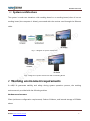
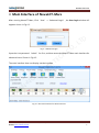


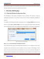


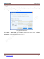


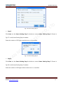
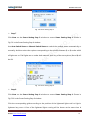

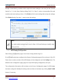


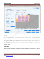
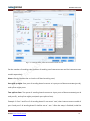
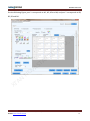
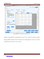
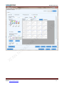
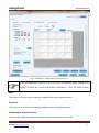

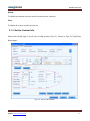
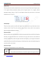


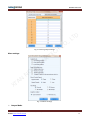

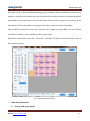

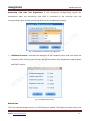


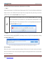
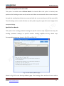
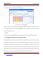


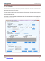


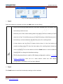


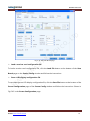
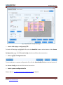


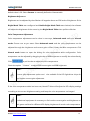
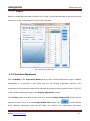
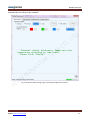
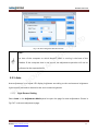
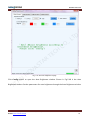
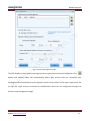
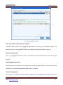
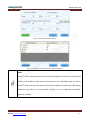


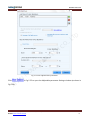
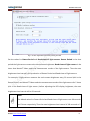
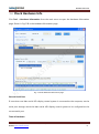

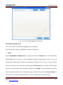

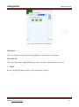

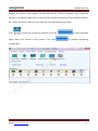
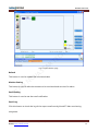
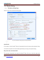

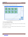
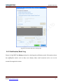
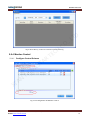
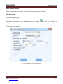


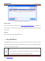
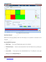
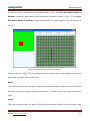
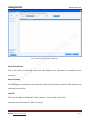


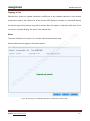
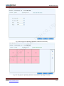
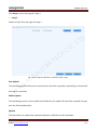
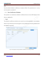

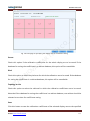

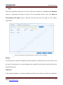
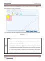
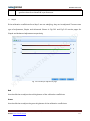
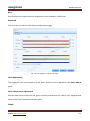
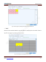
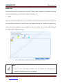
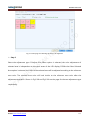
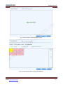
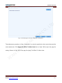

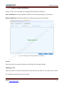
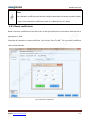
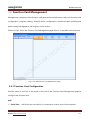
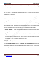
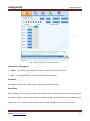


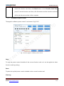
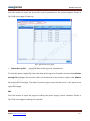
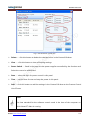
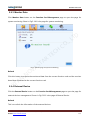
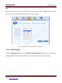

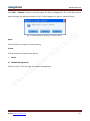


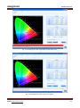
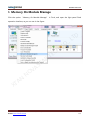

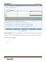
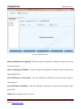
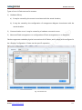
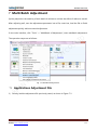
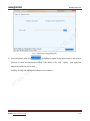


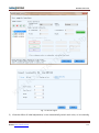
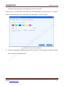
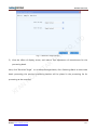
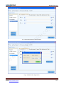

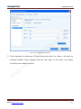

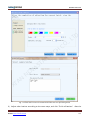

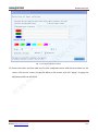

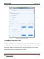


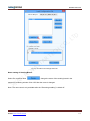

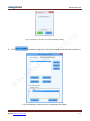
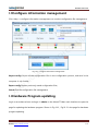
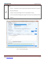
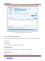

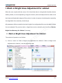
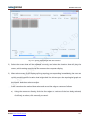
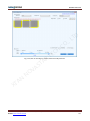


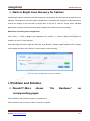
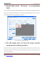
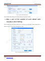
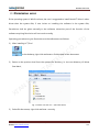
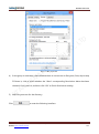


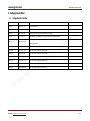


![English-T series-NOVA-User manual-F [兼容模式]](http://vs1.manualzilla.com/store/data/005791006_1-acba31ea472695c25db426bea2198a0f-150x150.png)