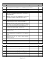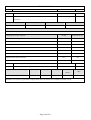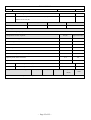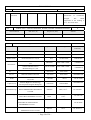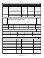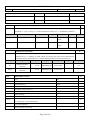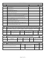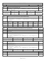
1
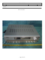
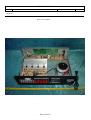
LABORATORIES
Report No:
File reference No:
LVD 0409123
2004-10-12
Applicant:
Guangzhou Hua Du Koda Electronics Co., Ltd
Product:
MULTI-CHANNEL AMPLIFIER
Model No:
AV-1068B
Trademark:
KODA
Test Standards:
EN 60065:2002
Test result:
The safety testing has been performed on the submitted samples
and found in compliance with the council LVD directive
73/23/EEC.
Approved By
Jack Chung
Manager
Dated:
October 12, 2004
Results appearing herein relate only to the sample tested
The technical reports is issued errors and omissions exempt and is subject to
withdrawal at
HONG KONG TIMEWAY TECHNOLOGY DEVELOPMENT LIMITED
Rm.1805, 18/F., Wu Sang house, Nathan Road, Mongkok, Kln. HONG KONG
Tel (852) 2781 7498
Fax (852) 2381 2492
EN 60065:2002
CL.
Requirement of the test
Result--Remark
Verdict
TEST REPORT
EN 60065: 2002
Audio, video and similar electronic apparatus-Safety requirements
Report reference No….…:
LVD0409123
Complied by (+signature):
Thomas Song
Approved by (+signature):
Terry Tang
Date of issue…………….:
2004-10-25
Testing Laboratory………:
HONG KONG TIMEWAY TECHNOLOGY DEVELOPMENT LIMITED
Address………………....:
Rm.1805, 18/F.,Wu Sang house, Nathan Road, Mongkok, Kln. HONG KONG
Testing Location………...:
Timeway Lab
Applicant………………...:
Guangzhou Hua Du Koda Electronics Co., Ltd
Address…………..……..:
33, Hongmian Road, Xinhua Industrial park, Xinhua Town, Hua Du District,
Guangzhou City, China
Standard………….…..….:
EN 60065: 2002
Test procedure………...…:
CCA_Scheme
Non_ standard test method:
N/A
Name of test object…… :
MULTI-CHANNEL AMPLIFIER
Rating……………………:
230V~ 50/60Hz 100W
Trade Mark………………:
KODA
Basic Model……………..:
AV-1068B
Additional Trade Mark…..:
N/A
Additional Model………..:
N/A
Manufacturer…….……..:
Same as applicant
Address…..…..…………:
Same as applicant
—
Page 2 of 2—
EN 60065:2002
CL.
Requirement of the test
Result--Remark
Possible test case verdicts:
--test case does not apply to the test object……….. : N (.A.)
--test object does meet the requirement……………: P(ass)
--test object does not meet the requirement……….. : F (ail)
General remark:
The test results presented in this report relate only to the object tested.
“See remark #” refers to one remark appended to the report.
“See appended table” reference to a table appended to the report
This report shall not be reproduced except in full without the written approval of the testing Lab.
The Difference between models: N/A
EUT LEBEL:
—
Page 3 of 3—
Verdict
EN 60065:2002
CL.
Requirement of the test
Result--Remark
Verdict
1.
Scope
--
2.
Definitions
--
3.
General requirement
P
Apparatus designed/constructed present no danger when used in
intended purpose
P
Constructed to ClassⅠor ClassⅡ apparatus
ClassⅡ
P
4.
General conditions for the test
Type test
--
5.
MARKING AND INSTRUCTIONS
P
Markings are permanent , Comprehensible & easily discernible
when ready for use
P
Location easily accessible/on the exterior
Location: Rear enclosure
P
Durability test (water and petroleum spirit)
Rubbing 15s
P
Letter and graphical symbols in accordance to specified standards
P
5.1
Identification and supply ratings
P
a.
Maker’s name/responsible vendor’s name/trade mark/ identification
mark
Please see page 2
P
b.
Model number or name
See page 2
P
c.
ClassⅡ symbol (symbol 417-IEC-5172)
“回”
P
d.
No requirements
e.
Nature of supply
~
P
f.
Rated supply voltage or voltage range
230V
P
g.
Rated mains frequency
50/60Hz
P
h.
Rated power or current consumption (supplied by supply apparatus)
100W
P
i.
Power consumption (apparatus connected to non-single phase a.c.
mains)
N
5.2
Terminals, marked as:
N
--
a) Protective earth terminal (symbol 417-IEC-5019)
b) Terminals in hazardous live under normal operating conditions
(symbol 417-IEC-5036)
No
hazardous
terminal
c) Voltage and current rating of output terminals connected to other
apparatus
No such terminal
N
No such outlet
N
Power & current rating of output terminals connected to other
apparatus
—
Page 4 of 4—
live
N
EN 60065:2002
CL.
5.3
5.4
Requirement of the test
Specific components for replacement provided with symbol
(triangle with exclamation mark)
Result--Remark
Near the components
Verdict
P
The symbol is on the
schematics
P
Instructions
Instruction for installations/use regarding safety provided.
5.4.1
Language acceptable to intended country
Language: English
P
a) Warning against water dripping or splashing
See the user manual
P
b) Warning against hazardous live terminals
See the user manual
P
c) Warning for use or replaceable lithium battery
The unit have no battery
N
d) A warning that an apparatus with class I construction shall be
connected to a mains socket outlet with a protective earthing
connection.
Class II
N
e) Instructions to ensure correct and safe installation and
interconnection of apparatus in multimedia systems.
N
f) If the apparatus is not be tested to the stability requirements of
19.1, 19.2 or 19.3 due to fastening in place
N
5.4.2
With regard to devices for disconnection from the mains,
instructions shall state
6.
HAZARDOUS RADIATION
N
6.1
Ionizing radiation,
Apparatus provide personal protection against ionizing radiation
N
Ionizing radiation ≤36pA/kg(0.5mR/h)
N
6.2
Laser radiation,
Apparatus with laser system provided personal protection against
laser radiation.
Adequate classification &label for emission level
6.2.1
6.2.2
See the user manual
P
The unit have no laser
system
N
--
N
a) Emission under normal conditions (test according to IEC 825)
N
b) laser system under normal conditions meeting ClassⅠlimits.
N
c) no opening of covers by hand give access to radiation in excess
of ClassⅠlimits
N.A .if comply b)
N
d) Interlock device comply fail-safe or withstand life test
N.A. if comply b)
N
a) Emission under fault conditions (test according to IEC825)
N
b) Laser system under fault conditions, meeting limits of 6.2.2 a.
N
—
Page 5 of 5—
EN 60065:2002
CL.
Requirement of the test
Result--Remark
Verdict
c) no opening of covers by hand give access to radiation in excess
of limits of 6.2.2 a
N.A. if comply b)
N
d) interlock device comply fail-safe or withstand life test
N.A. if comply b)
N
7.
HEATING UNDER NORMAL OPERATING CONDITIONS
7.1
General,
P
(See appended table)
P
Temperature rises not exceeding specified values
No operation of protective device
7.1.1
P
Accessible parts:
(See appended table)
P
- Temperature rise of accessible parts not exceed in table 2 item a
7.1.2
Parts (except windings) providing elect. Insulation:
-Temperature rise not exceed table 2 item b
(See appended table)
P
7.1.3
Parts as support/mechanical barrier:
(See appended table)
P
(See appended table)
P
(See appended table)
P
-Temperature rise not exceed table 2 item c
7.1.4
Windings:
-Temperature rise not exceed table 2 item b & d
7.1.5
Parts not subject to a limit under 7.1.1 to 7.1.4:
- Temperature rise not exceed table 2 item e
7.2
N
Heat resistance of insulating material,
Softening temperature of insulation material supporting parts
conductively connected to the supply mains carrying a mains
current﹥0.2 A at least 150℃
8
CONSTRUCTIONAL REQUIREMENTS WITH REGARD TO THE PROTECTION
AGAINST ELECTRIC SHOCK
P
8.1
Conductive parts covered by lacquer, solvent-based enamel, paper,
textile, oxide film are considered as bare live parts
P
8.2
Apparatus designed/constructed that normal operation/ user
maintenance not involve risk of shock. (See also 9.1.1)
No risk
P
8.3
Insulation of hazardous live parts not by hygroscopic materials
No hygroscopic material
P
Material comply Clause 10.3 after conditioning at 40℃,90-95%
R.H.
P
8.4
No risk of electric shock from accessible parts or removal cover
parts by hand
No accessible parts
removable by hand
P
8.5
For ClassⅠ, accessible conductive parts separated from hazardous
t b b i i l ti
classⅡ
N
—
Page 6 of 6—
EN 60065:2002
CL.
Requirement of the test
Result--Remark
Verdict
parts by basic insulation
8.6
Resistor bridging basic insulation comply 14.1a
N
Capacitor/RC unit bridging hazardous live & earthed accessible
conductive parts comply 14.2.1a
N
Resistor/Capacitor/RC unit situated inside apparatus enclosure
N
Accessible conductive parts reliably connected to protective earth
terminal/contact
N
For classⅡ,accessible parts separated from hazardous live parts by
double/reinforced insulation
(See also Clause 10 &
Clause
13
for
compliance)
P
Components comply14.1a or 14.3 may bridge double/reinforced
insulation.
Transformer
with cl.14.3
P
complied
Components complying 14.3.4.3 only may bridge basic insulation
Capacitor/RC units in same rating &comply 14.2.1a may bridge
basic/supply insulation
N
C3
Two capacitors/RC units in series of same rating & comply 14.2.1a
may bridge double /reinforced insulation
Resistor/Capacitor/RC unit situated inside apparatus enclosure
8.7
8.8
P
N
C3
P
For voltage between 35V to 71Vpk a. c. or 60V to 120V d.c. under
normal/fault conditions, basic insulation meeting Cl.10&13
acceptable
N
For circuits in higher voltages, for class Ⅱ , required
double/reinforced insulation or classⅡ construction transformer
P
For circuits in higher voltages, for class Ⅰ ,required earthed
conductive part or classⅠconstruction transformer
N
Basic, supplementary, reinforced insulation withstand electric
strength test of 10.3
(See also Clause 10.3)
P
For double insulation, either basic or supplementary have thickness
of at least 0.4mm
P
Reinforced insulation of at least 0.4mm not subjected to mechanical
stress.
P
Requirements for thin layers of insulation
(See also clause 10.3)
P
Type of insulation………………………………………………..
Reinforced Insulation
P
Number of layers…………………………………………………
3 layers insulation Tape
P
—
Page 7 of 7—
EN 60065:2002
CL.
8.9
Requirement of the test
Result--Remark
Insulation of internal wiring in hazardous live to accessible
Verdict
0.65mm
P
conductive parts at least of 0.4mm thickness
8.10
Conditions for requiring double insulation in ClassⅡ apparatus
See also
&10.3
Clause
8.9
P
8.11
No reduction of CR/CL of detachable wire
All wires fixed
reliable manner
in
P
8.12
Conductors of internal wiring connecting mains socket-outlets to
the mains terminal comply with cross-sectional area of 16.2
No socket outlet
8.13
Windows, lenses, signal lamp cover fastened by positive means if
hazardous parts accessible. 20N 10s
Adequately
No damage
fastened
P
8.14
Covers subjected to forces fastened by positive means if hazardous
parts accessible
Covers
adequately
fastened with screw
P
Test by 50N force for 10s
No hazardous live parts
become accessible
P
Internal wiring of which will cause hazard in case of damages be
secured not contact parts of impermissible temperature
and
No risk of damage to
insulation due to high
temperature,
sharp
edges, moving parts or
pinches
P
8.15
P
Secured that no risk of mechanical damage of sharp edges, moving
parts etc.
P
8.16
Apparatus supplied with specified supply apparatus constructed that
not able replaced by general supply apparatus.
N
9
ELECTRICAL SHOCK HAZARD
OPERATING CONDITIONS
P
9.1.1
General,
UNDER
NORMAL
P
Hazardous live parts not accessible
Inaccessible contact of a terminal not hazardous live if: (with
exemptions)
P
a) Open circuit voltage not exceed 35Vpk a. c. or 60V d.c.
Complied with (b)
N
If a) is not met, b) Touch current (IEC60990), not exceed
U2=0.08V
P
for a.c. U1=35V pk and U2=0.35V pk
for d.c. U1=1.0V
and moreover
c) Discharge not exceed 45uC for stored voltages between 60V and
15kV
or
—
Page 8 of 8—
N
EN 60065:2002
CL.
Requirement of the test
Result--Remark
d) energy discharge not exceed 350mJ for stored voltages
exceeding 15kV
N
Locations of terminals in hazardous live………………………
--
Tested by means of a test finger. 20N
No access for the test
finger
P
Tested by means of a test probe. 3N
No access for the test
probe
P
9.1.2
Shafts of operating knobs, handles, levers and the like not be
hazardous live.
9.1.3
Apparatus not designed that suspended foreign bodies become
hazardous live
P
No such component
Test with 4mm diameter and 100mm long pin
9.1.4
Verdict
N
N
Terminal devices test by means of 1mm × 20mm test probe (10N)
No hazard
P
Terminal devices test by means of 1mm × 100mm test probe (1N)
No hazard
P
9.1.5
Pre-set controls test by means of 2mm × 100mm test probe (10N)
No pre-test control
N
9.1.6
No risk of electric shock from withdrawal of mains plug (if with C
≥0.1uF)
C3 0.01uF<0.1uF
P
9.1.7
Resistance to external force, tested by:
P
a) 50N with a rigid test finger
Hazardous live part no
accessible
P
b) 20N with test hook
Hazardous live part no
accessible
P
c) Steady force: -250N for floor-standing
100N
P
A tool is necessary to
remove covers
N
-100N for other types
9.2
Removable protective covers not give access to hazardous live
10.
INSULATION REQUIREMENTS
P
10.1
Surge test: Insulation between accessible parts to hazardous live
withstand surge through antenna terminals
N
Insulation test (Cl.10.3) after 50 times 10kV discharge test
N
10.2
Humidity treatment test
Duration: 48hours
P
T=30℃, R.H=95%
10.3
Insulation resistance and dielectric strength
—
(See appended table)
Page 9 of 9—
P
EN 60065:2002
CL.
Requirement of the test
Result--Remark
Verdict
11.
FAULT CONDITIONS
P
11.1
Protection against electric shock exist when apparatus under fault
conditions (Comply Cl.9)
P
11.2
Heating
(See appended table)
P
11.2.1
Measurement of temperature rises
Thermocouple
-
11.2.2
Temp. rise of accessible parts not exceed table 2a)
(See appended table)
P
11.2.3
Temp. rise of parts (exclude windings) providing electrical
insulation comply table 2b)
(See appended table)
P
For PCB, temp. rise may exceed table 2b)by not more than100K for
5 min.
N
For PCB withstanding the flame test of 20.1., temp. rise may
exceed 2b)……….
P
Acceptance criteria for Interruption/peeled/loosened of conductors
on PCB, if -PCB comply 20.1.3
&
N
-no reduction of CR/CL
&
N
-Not as a potential ignition source
&
N
-comply subclause with the interrupted conductor bridged
&
N
-ClassⅠ,earthing continuity is maintained
N
11.2.4
Temp. rise of parts as support/mechanical barrier not exceed table
2c)
N
11.2.5
Temperature rise of windings not exceed table 2b) & d) EXCEPT
(See appended table)
P
That values may exceed:
-until 2 min if limited by operation of replaceable/reset-able
protective devices &
N
-comply Clause 10.3 after (if windings give shock protection or
fault result fire hazard)
-if limited due to operation of integral non-reset-table or
non-replaceable protective device due to the open-circuit of
winding &
N
-comply Clause 10.3 after (if windings give shock protection or
fault result fire hazard)
- failure of insulation not cause electric shock/fire hazard & not
connected to sources supplying 5W in excess.
N
- no hazard If insulation concerned bridged & comply repeated test
of 11.1 & 11.2.2
N
—
Page 10 of 10—
EN 60065:2002
CL.
Requirement of the test
Result--Remark
Verdict
11.2.6
Parts not subject to a limit under 11.2.1 to 11.2.5 not exceed
table2e)
(See appended table)
N
12.
MECHANICAL STRENGTH
P
12.1
Complete apparatus,
P
Apparatus have adequate mechanical strength and constructed
withstand such handling
12.1.1
Bump test-50 times 5cm drop
Mass=4.74kg
P
P
(for apparatus>7kg)
12.1.2
Vibration test
No damage
12.1.3
Impact test (2J), and then Hi-pot test
No
damage,
breakdown
12.1.4
Drop test
No need
N
12.1.5
Stress relief test
Metal enclosure
N
12.2
Actuating elements, knobs, push-buttons, keys & levers constructed
that use not impair protection against electric shock
N
Pulling, push & torque test
N
Remote control device held in hand
N
Tumbling barrel test
N
12.4
Drawers, 50N pulling force test
N
12.5
Antenna coaxial sockets mounted on apparatus
N
12.3
No
P
Tested by:
-100 times insert/withdraw endurance test
13.
-0.5J impact test for 3 times
N
-10 times 50N right angle torque test
N
CLEARANCES AND CREEPAGE DISTANCES
P
Creepage distances and clearances not
exceeded specified limit
Between primary winding and secondary winding,
measured: 6.0mm (limit is ≥6.0mm)
P
Between different polarity directly connected to
the mains (CL/Cr), measured:3.0mm (limit is ≥
3.0mm)
P
Between bottom enclosure to live parts (CL),
measured: 6.0mm. (Limit is ≥6.0mm)
P
—
Page 11 of 11—
EN 60065:2002
CL.
Requirement of the test
Result--Remark
Verdict
Between solder track of capacitor 35C3 (CL/Cr),
measured: 6.0mm. (Limit is ≥6.0mm)
P
Between transformer and top enclosure (CL/Cr),
measured: 6.0mm. (Limit is ≥6.0mm)
P
14.
COMPONENTS
P
14.1
Resistor,
N
Have stable resistance value & positioned inside the enclosure
a) R bet. Live & accessible cond. Parts or R bridging sw. gap. 10
samples subjected 50 times 10kV discharge test,
N
b) 10 samples with 1.5 times test current (for other resistors)
N
Creepage distances and clearances between terminations comply
Cl.13 reinforced insulation
N
14.2
Capacitors or RC units
C3
14.2.1
a) Withstand tests for subclass Y2 or Y4 (tableⅡ of IEC60384-14)
N
Correct application of Y2 or Y4 components
N
b) Withstand tests for subclass Y1 or Y2 (tableⅡ of IEC60384-14)
Y1
P
P
Correct application of Y1 or Y2 components
P
Components are positioned inside the enclosure of the apparatus
P
Capacitors and RC units directly connected to mains withstand the
tests for subclass x1 or x2 (tableⅡ of IEC60384-14)
N
Correct application of x1 or x2 components
N
14.2.3
Capacitors or RC units in a.c. circuits with mains frequency not to
mains withstand tests for subclass x2 (tableⅡ of IEC60384-14)
N
14.2.4
No requirement
N
14.2.5
Capacitors or RC units need to comply passive flammability of
IEC60384-1
N
-exceeding volume 1750mm3 with s/c current exceed 0.2A
N
-exceeding volume 1750mm3 & distance between potential ignition
source not exceed table specified
N
No requirements for capacitor or RC units if:
N
14.2.2
-shielded by barrier meeting flammability cat. FV0 of IEC60707 of
specified dimensions
-barrier of metal of specified dimensions
—
Page 12 of 12—
EN 60065:2002
CL.
Requirement of the test
Result--Remark
14.3
Inductors and windings
14.3.1
Inductors marked with:
Manufacturer:
-Manufacturer name/ trade mark /code ref.
(See appended table)
-type or catalogue references / code ref.
1: 198 AV-1068B
Verdict
P
P
P
2: HP-100-01
14.3.2
For windings in form of
Isolating transformer
P
-transformer type…………………………………………………
-others…………………………………………………………….
N
Comply with –14.3.3
and
P
-14.3.4.1 or 14.3.4.2
and
Comply with CL14.3.4.1
P
-14.3.5.1 or 143.3.5.2
Comply with CL14.3.5.1
P
Insulating material of inductor comply 20.1.4
Insulation tape
P
14.3.3
Constructional requirements
14.3.3.1
CR/CL of all windings comply Clause 13
14.3.3.2
Design with more than one windings
P
Position and layer of adhesive bond on winding partition wall side
P
Precautions taken prevent undue displacement of windings and
bridging of insulation
P
Last turn of windings retained in position
P
End turns of each layer of winding retained in reliable manner for
cheekless bobbins
P
14.3.4
Separation between windings
P
14.3.4.1
Windings of ClassⅡ construction
P
Separation between windings at hazardous live and accessible pars
in: -double /reinforced insulation according to 8.8
or
P
-0.4mm thickness of insulation
N
If the presence of conductive part, insulation between via this
intermediates metal part consists of double or reinforced insulation.
P
Windings of ClassⅠ construction
N
Separation between hazardous live windings to accessible parts
consists of basic insulation plus protective screening with ALL
CONDITIONS met
N
Windings of separating construction
N
14.3.4.2
14.3.4.3
P
—
See also Clause13
Page 13 of 13—
P
EN 60065:2002
CL.
Requirement of the test
Result--Remark
Verdict
Separation between hazardous live windings and windings intended
to be connected to parts separated from accessible parts by
supplementary insulation consists of at least basic insulation of 8.8
N
14.3.5
Insulation between hazardous live parts and accessible parts
P
14.3.5.1
Windings of ClassⅡ construction
P
Hazardous live windings to accessible parts &
P
Hazardous live parts to accessible conductive
Consists of :- double/reinforced insulation
or
- 0.4mm partition wall thickness
14.3.5.2
14.4
N
Windings of ClassⅠconstruction
N
Hazardous live windings / parts to accessible conductive parts
consists of basic insulation
N
Windings current-carrying capacity ensure fusing or interrupt
device operate before winding destroyed
N
High voltage components and assemblies
N
Components details (type, rating & locations)……………………
14.4
N
High-voltage components and assemblies;
U>4Kv (peak to peak), normal use and fault conditions give no
danger, fire risk
14.4.1
High-voltage multipliers and transformers,
N
Subjected to flame test (Annex G) after conditions treatment
14.5
Protective device,
Their ext. CR/CL & connections meet Cl.13 basic insulation
(See appended table)
P
Components details (type, rating & locations)……………………
See appended table
---
External CR/CL of protective device & their connections comply
basic insulation of Cl..13
14.5.1
Thermal release
P
Thermal link
P
Components details (type, rating & locations)……………………
External CR/CL of protective device & their connections comply
basic insulation of Cl. 13
14.5.2.2
Appropriate marking for fuse link provided:
P
F
P
- rated current in milliampere or ampere
See appended table
P
- breaking capacity
L
--
- symbol for pre-arcing time/current characteristics
—
Page 14 of 14—
EN 60065:2002
CL.
Requirement of the test
Result--Remark
14.5.2.3
Fuse holder designed that fuse-links connected in parallel in the
same circuit not used
P
14.5.2.4
If hazardous live parts accessible during replacement, access not
possible by hand
N
Fuse holders comply with IEC60127-6
N
or
No hazardous live parts accessible during inserting/moving or after
removal of fuse
14.5.3
PTC-s thermistors comply with IEC60783
Verdict
N
No such component
N
Components details (type, rating & locations)……………………
Encapsulating or tubing comply FV1 of IEC
N
14.5.4
Protective device not mentioned in above have adequate breaking
capacity and marking
No other
device.
14.6
Switches
(See appended table)
P
Components details (type, rating &locations)……………………
P12 5/80A 250V
P
Permanently connected apparatus provided with all-pole mains
switch with 3.0mm separation in each pole except 5.4.2 met.
Not a permanently
N
14.6.1
14.6.2
protective
connected apparatus
Manually-operated mechanical (MOM) switch if:
- power consumption >15W
P
& / or
- employs a peak voltage 4Kv
N
The switch in off position, connected that:
-power consumption=15W
& / or
0W (Single pole mains
switch)
-pk voltage=4Kv under normal/fault conditions
N
‘ON’ indication for on-position of power switch of 14.6.2
P
‘OFF’ indication for off-position of all-pole main switch
P
Information states situation of switch / control marking
14.6.4
P
N
REASONS:
IF NOT REQUIRED
14.6.3
N
Near the switch
P
Stand-by indication clear and discernible
N
Indications by……………………………………………………
--
14.6.5
Resistor, capacitors, RC units bridging contact gaps comply with:
N
14.6.6
Testing of MOM switches conductively connected to the mains
comply with
a) tested as separate components comply IEC61058 with specified
conditions:
—
Page 15 of 15—
Comply with IEC61058
N
N
EN 60065:2002
CL.
Requirement of the test
Result--Remark
Appropriate rating and classifications of switch
Verdict
--
b) tested as part of the apparatus meet 14.6.7, 14.6.10&20.1.4 and
specified conditions
N
14.6.7
Withstand 10,000 cycles tests
N
14.6.8
Temperature test of switch with terminations not exceed 55K
14.6.9
Switch withstand 10.3 dielectric strength test (75% of specified
values)
N
14.6.10
Endurance test for switch with additional load to socket-outlets
N
14.7
Safety interlocks
14.8
(See appended table)
No such component
14.9.1
N
Components details (type, rating & locations)……………………
--
Reference to IEC60950 subclause 2.8
N
Voltage setting devices and the like
No such component
Changing the voltage setting devices and the like not likely to occur
accidentally
14.9
N
Motors
N
N
The unit has no motors.
N
Components details (type, rating & locations)…………………
--
Motors constructed that electrical or mechanical failure, insulations
not affected and connections/ contact not work loose
N
a) each 48 hours endurance test at 0.9 and 1.06 times rated voltage
N
b) each 50 times starting test at 0.9&1.06 times rated voltage
N
After test,:
N
- withstand dielectric strength test 10.3
- no connection loosened & deteriorate
N
14.9.2
Motors constructed/mounted that windings, wiring, commutators,
insulations not affected by oil, grease or the like.
N
14.9.3
Adequate protections provided for moving parts cause personal
injury
N
Protective enclosures/guards have adequate mechanical strength
and not removed by hand
N
14.9.4
Motors having phase-shifting capacitors, three-phase motors and
series motors, IEC60950 annex B Clause B8, B9&B10 apply
N
14.10
Batteries
N
Components details (type, rating &locations)………………….
--
Batteries mounted that no risk of accumulation of flammable
&l k
f li id t i
i i l ti
N
14.10.1
—
Page 16 of 16—
EN 60065:2002
CL.
Requirement of the test
Result--Remark
Verdict
gases& leakage of liquid not impair insulation
14.10.2
For user replace rechargeable batteries, means provided to prevent
charging of non-rechargeable batteries.
N
14.10.3
No possibility of having non-permissible value under normal/fault
conditions for:
N
- for rechargeable batteries for charging current or charging time
- for lithium batteries, discharging current or the reverse current
14.11
Optocouples
N
No such components.
N
Components details (type, rating & locations)……………………
--
Optocouples comply with constructional requirements of clause 8
P
15.
TERMINALS
P
15.1
Plugs &sockets
15.1.1
Mains plug, appliance inlet, connector, mains socket-outlet
comply with relevant IEC requirements
(See appended table)
Mains socket outlet/couplers of ClassⅡ only permit connection
to other ClassⅡapparatus
P
P
No socket outlet
N
Mains socket outlet/couplers of ClassⅠ allow connection of
ClassⅡ only or provided with protective earth contacts
N
No overload of plugs/appliance inlet for apparatus with
socket-outlets provides power to other units.
N
Internal wiring of s/o have nominal X-sectional as specified as
16.2 for external flexible cables
N
Plug not for mains connection designed that unlikely to insert
into mains socket-outlet
P
No insertion possible of plugs for antenna, earth, sound, video
without “flash” symbol able to connect to connectors marked
with “flash” symbol
N
15.1.3
Terminals with non-standard mains voltage (IEC60338) used in
the output circuits of supply apparatus not compatible with those
of described in IEC 60083,60320,60884,60906
N
15.2
Provision for protective earthing
N
Adequate earthing provision for ClassⅠapparatus and protective
earth contacts of socket-outlets
N
No switch/fuse within earthing circuit
N
15.1.2
—
Page 17 of 17—
EN 60065:2002
CL.
15.3
15.3.1
Requirement of the test
Result--Remark
Verdict
Appropriate colour for earhing conductor
N
Perm. Connected/non-detachable cord connected with earthing
terminal adjacent to mains and not fixes other component.
N
For parts removable by hand, comply the make and break
sequence for earthing & current carrying connections
N
Earthing terminal resistant to corrosion
N
Earth resistance test
N
Limit: <0.1 Ohms
Terminals for external flexible cords& for permanent connection
to the mains supply
Not a permanently
N
connected apparatus
Appropriate connections means provided for terminals
N
For inlet openings, comply with IEC60335-1
N
Reliable means provided for supply cord connect to internal
wiring.
N
No direct soldering of supply/earth wire to pcb
N
Conductors fixed reliably of no possibly reducing CR/CL in case
of lossening/slip/solder breaks (Check by 5N pulling test)
N
Screws/nuts for mains connection comply with ISO 261 or 262
N
Not fix other components except internal wiring if not displaced
when fitting mains conductors
N
15.3.4
Adequate fixing of terminal conductors
N
15.3.5
Terminals allow connection for required conductor size
N
15.3.6
Terminals with size not less than specified
N
15.3.7
Terminals designed that:
N
15.3.2
15.3.3
- Conductor clamped between metal surface with sufficient
contact pressure & without damage
15.3.8
For > 0.2A, terminal with contact pressure not transmitted
through insulating material.
N
15.3.9
Proximity location of terminals and no accident contacts to
adjacent terminals
N
15.4
Devices forming a part of the mains plug
N
15.4.1
No undue strain impose on socket outlets
N
Torque test, limit:<0.25Nm
15.4.2
Plug-in device comply with relevant standard dimension
requirements
—
Page 18 of 18—
N
EN 60065:2002
CL.
15.4.3
Requirement of the test
Result--Remark
Verdict
Device have adequate mechanical strength
N
a) 1m drop test
N
b) 0.4Nm 1 min pin turning test
N
c) 1 min pin test after 70℃ conditioning
N
16.
EXTERNAL FLEXIBLECORDS
P
16.1
Mains supply cords comply relevant IEC standard
(See appended table)
Non-detachable flexible cords for Class Ⅰ provided with
green/yellow core connected to PE terminal
N
Size: 2×0.75mm2
16.2
Cross-sectional area not less than specified
16.3
Other non-IEC flexible cords with live conductors connected
between apparatus (used in combinations) comply with:
P
P
N
-El. Strength test 10.3w/ref.to IEC60885-1
-Stress/mech. Tests ref. To IEC60227-2
N
16.4
Adequate cross-sectional areas that have no excessive temp. rise
of the insulation.
(See CL 7 & 11.)
P
16.5
Acceptable type/construction of the cord anchorage
Type: Bushing
P
Pull test (40N, 100 times)
No displacement
P
Torques test (0.25 Nm, 60s)
No displacement
P
16.6
Apertures constructed that no risk of damage to cord during
introduction
Means: Bushing
P
16.7
For transportable apparatus provided:
Not a
apparatus
N
- appliance inlet to IEC60320-1.
or
transportable
- means of stowage to protect mains cord
N
17
ELECTRICAL CONNECTIONS AND MECHANICAL FIXINGS
P
17.1
Adequate strength provided for electrical screw terminals/screws
fixings, (Torque test)
P
(See appended table)
Screw exerting contact pressure of less than 3.0mm screw into
metal
P
17.2
Correct introduction of
non-metallic materials
in
P
17.3
Screws/other fixing devices captive to prevent replacement that
reduce required CR/CL
P
screws
into
—
female
threads
Page 19 of 19—
EN 60065:2002
CL.
Requirement of the test
Result--Remark
Verdict
17.4
Conductive parts permanently fixed together in >0.2A secured
to prevent loosening.
N
17.5
For > 0.2A, terminal with contact pressure not transmitted
through insulating material.
N
17.6
Stranded conductor ( > 0.2A), not consolidated by lead-tin
soldering if subject to contact pressure
N
17.7
Adequate mechanical strength for cover-fixing devices
P
Locked & unlocked position snot ambiguous & not able to
unlock inadvertently.
N
10 times test (rotary/linear movements)
P
10 times remove/fixing test (snap fasteners)
N
17.8
Detachable legs/stands supplied by the manufacturer delivered
with relevant fixing means
N
17.9
Unlikely of loosening of internal pluggable connections (Pull
with 2N force)
P
18.
MECHANICAL STRENGTHOF PICTURE TUBES ANDPROTECTION AGAINST
THE EFFECTS OF IMPLOSION
N
18.1
Picture tube ( > 16cm)intrinsically protected to effects of
implosion & mechanical impact
N
By apparatus enclosure/
Protective shields
Size of picture tube………………………………………………
N
Manufacturer……………………………………………………
N
Type………………………………………………………………
N
Tested according to……………………………………………
N
By…………………………………………………………………
N
18.2
Intrinsically protected picture tubes, including those having
integral protective screens
N
18.2.1
Details for ageing process
--
18.2.2
Implosion test
N
18.2.3
Mechanical strength test
N
18.3
Implosion test (non-intrinsically protected picture tubes)
N
19.
STABILITY AND MECHANICAL HAZARDS
P
19.1
Apparatus exceeding 7kg have adequate stability
—
Page 20 of 20—
Mass=4.74kg
P
EN 60065:2002
CL.
Requirement of the test
Result--Remark
Verdict
19.1
Test on a plane10º inclined to the horizontal
P
19.2
100N test to parts drawn out of the apparatus
P
19.3
Edges/corners smoothed not be hazardous to user
No sharp edges
P
19.4
Glass (>0.1m2 or >450mm major dim.) not be shattered to
result skin lacerating injury.
No glass
N
19.4.1
Fragmentation test
20.
20.1
N
RESISTANCE TO FIRE
P
Apparatus designed start and spread of fire prevented
P
Electrical components and mechanical parts 20.1.1-4 not apply for
those under………………………………………………………….
P
20.1.1-4 not apply for those under………………….………………
Exemption a) /b)
20.1.1
Electrical components comply………………………………………
Clause 14 / Clause20.1.4
20.1.2
Insulation of wiring not contribute spread of fire
P
Compliance test (Annex G.2)
P
Printed boards (>15W at 50-400Vpk at normal),
P
20.1.3
- flammability grade ≥ FV1
or
- pcb protected by enclosure in……………………………………
Grade: 94V-0
P
Metal
P
PCB (>15W at 400V-pk at normal &support spark gaps):
- flammability grade≥FV1
20.1.4
N
or
N
- pcb protected by enclosure in…………………………………….
N
Compliance test……………………………………………………..
IEC 60707 / annex G.1
N
Components/parts not covered by 20.1.1,20.1.2 &20.1.3 except fire
enclosure
Enclosure
P
- of flammability grade (table13)
Metal enclosure
P
or
- shield by a barrier of adequate dimensions in
N
Compliance test…………………………………………………….
N
20.2
Fire enclosures
20.2.1
Potential ignition sources (O/C > 4kVpk) contained in fire
enclosure of grade at least FV1
Metal enclosure
Compliance test…………………………………………………….
20.2.2
P
Internal fire enclosure have openings for ventilation>1mm in
width regardless of length
—
Page 21 of 21—
N
N
IEC60707 / Annex G.1
N
N
EN 60065:2002
CL.
20.2.3
Requirement of the test
Result--Remark
If internal enclosure or internal wiring (comply 20.1.2) met
20.2.1&2.2.2, no requirements for outer enclosure
Verdict
N
APPENDIX
--
A
ADDITIONAL REQUIREMENTS FOR APPARATUSWITHPROTECTION AGAINST
SPLASHING WATER
N
5.1
Apparatus with protection against splash water marked with IPX4
N
5.4.1
5.4.1a not apply
--
10.2.1
Splash test, IEC60529 14.2.4
N
10.2.2
Humidity treatment 7 days
N
B
APPARATUS TO BE CONNECTED TO THE TELECOMMUNICATION NETWORKS
N
5.4.1
e) Instruction state the integrity of PE shall be ensured
N
-double/reinforced insulation(8.6)
or
- basic insulation + protective earthing
N
8.2
Other than above, TNV separated from cct. & from accessible
conductive parts by basic insulation (req. CR/CL)
N
9.1.1
Contacts of terminals for TNV not touched by figure B.1 exempt
from the requirements for inaccessible terminal contacts
N
9.1.4
Straight test probe D, IEC61032 applied to TNV circuit terminals.
N
10.1
Insulation bet. TNV circuit terminal & antenna terminals or to
inter-connected antenna terminals subjected to 50 discharges
N
10.3
Test voltage between TNV cct. & other parts determined according
to operating voltages as B8.1
N
14.12
Surge suppressors,
N
If connected bet. TNV cct. & other parts of the apparatus, surge
suppressors have nominal d.c. spark voltage at least 1.8 times of the
rated mains voltage.
C
BAND-PASS FILTER FOR WIDE-BAND NOISE MEASUREMENT
--
D
MEASURING NETWORK FOR TOUCH CURRENT
--
E
MEASUREMENT OFCLEARANCES AND CREEPAGE DISTANCES
--
F
TABLE OF ELECTROCHEMICAL POTENTIALS
--
G
FLAMMABILITY TEST METHODS
--
N
ROUTINE TEST
--
P
BIBLIOGRAPHY
--
—
Page 22 of 22—
EN 60065:2002
CL.
Requirement of the test
Result--Remark
Verdict
ZA
OTHERINTERNATIONALPUBLICATIONS QUOTEDIN THIS STANDARD WITH
THE REFERENCES OF THE RELEVANT EUROPEAN PUBLICATIONS
--
ZB
ANNEX ZB TO EN 60 065, SPECIAL NATIONAL CONDITIONS
N
2.6.1
DK: certain types of ClassⅠapparatus, see 15.1.1, may be provided
with a plug not establishing earthing continuity when inserted in
Danish socket outlets
N
15.1.1
DK: supply cords of single phase appliances having a rated current
not exceeding 10A shall be provided with a plug according to
N
Heavy Current Regulations Section 107-2D1
DK: ClassⅠappliance provided socket outlets with earthing contact
provided with plug in accordance with standard sheet dk 2-1a
N
DK: socket outlets for providing power to ClassⅡapparatus with
rated current≤2.5A shall have dimensions according to specified
drawing. Other dimension shall be according to IEC83 Sheet C1a.
N
DK: socket-outlets with earthing contact shall be incompliance with
section 107-2-D1 standard sheet DK 1-3a or DK 1-7a.
N
IR: apparatus fitted with flexible cable cord provided with 13A plug
( Statutory 525:1997)
N
NO: mains socket outlets on ClassⅡapparatus meet requirements
of Cee7 with amendments in Cl.8 dimensions & Cl.24 Mechanical
strength.
N
GB: BS1363 mains plug shall comply to Statutory Instrument
regulations 1768:1994
N
B.5.4.1
NO, SI (Notes added)
N
B.8.1
DK, NO (Notes added)
N
B.14.12
DK, NO, SI (Notes added)
N
ZC
ANNEX ZC TO EN 60 065, A-DEVIATIONS
N
5
DE: additional markings required for
N
-cathode-ray tubes with an accelerating voltage between 20kV to
30kV
-TV receivers with an accelerating voltage exceeding 30kV
N
N
-TV receivers with an accelerating voltage not exceeding 20kV
N
5.1
IT: additional marking on outside of TV receiver
N
6.1
De: TV receivers: ionizing radiation within limits
N
—
Page 23 of 23—
EN 60065:2002
CL.
Requirement of the test
7.1
Result--Remark
Verdict
Table: temperature rise measurements
P
Power consumption in the OFF/stand-by position of the functional
switch (W)…………………………………………………………..
0
Un (V)
In (A)
Pin (W)
Pout (W)
253
0.472
94
--
Operating conditions
1/8 max Non-clip output power & all ventilations blocked
Temperature rise dT of part/at:
dT (K)
Required dT (K)
Transformer winding
61.9
70
Switch body (inside)
29.6
40
PWB near heat sink
92.3
105
C122 body
47.7
80
PWB near D161
66.1
105
Transformer output wire (Secondary)
40.6
80
Operate panel (front enclosure)
19.8
40
Top enclosure near heat sink
38.3
40
Ambient temperature t1 (℃) ………………………………………:
25℃
Ambient temperature t2 (℃) ………………………………………:
25℃
Temperature rise dT of winding:
R1 (Ω)
R2 (Ω)
dT (K)
Required
dT(K)
Insulation
class
A
Remarks: Fuse current is equivalent to input current since current fuse was installed in primary circuit
—
Page 24 of 24—
EN 60065:2002
CL.
7.1
Requirement of the test
Result--Remark
Verdict
Table: temperature rise measurements
P
Power consumption in the OFF/stand-by position of the
functional switch (W)……………………………………………..
0
Un (V)
In (A)
Pin (W)
Pout (W)
207
0.451
74.5
--
Operating conditions
1/8 max Non-clip output power& all ventilations blocked
Temperature rise dT of part/at:
dT (K)
Required dT (K)
Transformer winding
56.3
70
Switch body (inside)
25.2
40
PWB near heatsink
75.4
105
C122 body
40.6
80
PWB near D161
60.0
105
Transformer output wire (Secondary)
36.4
80
Operate panel (front enclosure)
17.4
40
Top enclosure near heatsink
35.0
40
Ambient temperature t1 (℃) ……………………………………:
25℃
Ambient temperature t2 (℃) ……………………………………:
25℃
Temperature rise dT of winding:
R1 (Ω)
R2 (Ω)
dT (K)
Required
dT(K)
Remarks: Fuse current is equivalent to input current since current fuse was installed in primary circuit
—
Page 25 of 25—
Insulation
class
EN 60065:2002
CL.
Requirement of the test
7.1
Result--Remark
Verdict
Table: temperature rise measurements
P
Power consumption in the OFF/stand-by position of the functional
switch (W)…………………………………………………………..
0
Un (V)
In (A)
Pin (W)
Pout (W)
253
1.05→0
232→0
--
Operating conditions
Max Non-clip output power& all ventilations blocked
Temperature rise dT of part/at:
dT (K)
Required dT (K)
Transformer winding
110
135
Switch body (inside)
31
65
PWB near heat sink
88
105
C122 body
47
80
PWB near D161
96
105
Transformer output wire (Secondary)
49
80
Operate panel (front enclosure)
21
65
Top enclosure near heat sink
45
65
Ambient temperature t1 (℃) ………………………………………:
25℃
Ambient temperature t2 (℃) ………………………………………:
25℃
Temperature rise dT of winding:
R1 (Ω)
R2 (Ω)
dT (K)
Required
dT(K)
Insulation
class
A
Remarks: Fuse current is equivalent to input current since current fuse was installed in primary circuit
The thermal link of transformer damaged after 10mins.
—
Page 26 of 26—
EN 60065:2002
CL.
7.2
Requirement of the test
Verdict
Table: softening temperature of thermoplastics
Temperature T of part
10.3
Result--Remark
N
T – Normal conditions (℃)
T – Fault conditions (℃)
T softening (℃)
TABLE: insulation resistance measurements
P
R (MΩ)
Insulation resistance R between
After 10.1
After 10.2
(MΩ)
--
>50MΩ
4 MΩ
Live parts to Audio output terminal
10.3
TABLE: insulation resistance measurements (for Clause 14. components)
N
R (MΩ)
Insulation resistance R for Components:
10.3
Limit
Limit
(MΩ)
TABLE: electric strength measurements
P
Test Voltage (V)
Test Voltage applied between
Live to Audio output terminals
10.3
After 10.1
After 10.2
-
3000
Test voltage
Primary to secondary
No
No
TABLE: electric strength measurements (for Clause 14. Components)
Test voltage applied for COMPONENTS: transformer
11.
Breakdown
(V)
P
Breakdown:( V)
3000
No
P
Table: Fault condition tests
Rated voltage (v) …………………………………………………:
230V
--
Rated input (w) ……………………………………………………:
100
--
Room temperature (℃)……………………………………………:
25℃
--
Component
1
D160
2
C121
Fault
SC
SC
Test voltage
Test time
AC253V
5mins
F1
0.5A
F3 damaged at once. No other
components
damaged.
No
breakdown.
AC253V
1sec
F1
0.044A
F2/F3 damaged at once. No
other components damaged. No
breakdown.
—
Fuse No
Page 27 of 27—
Fuse
current
Result
EN 60065:2002
CL.
3
Requirement of the test
Transformer
blue-black
12.2
SC
AC253V
1min
Result--Remark
F1
0
Verdict
The unit shut down. The
thermal-link of transformer
damaged.
The
MAX
temperature of the winding is
127℃. No break down.
TABLE: PULL / TEST ON HANDLES, KNOBS, LEVERS ANDSIMILAR PARTS
Part under test
Pull force (N)
Torque test (Nm)
N
Results
Note:
14
P
Table: list of critical components
Part Name
Manufacturer
Type/model
Rating
Mark(s) of
conformity
Power cord
Chau's Electrical Co. Ltd.
H03VVH2-F
2×0.75mm2.
VDE121254
Chau's Electrical Co. Ltd.
CE-503
AC250V 2.5A
VDE080424
P12
5A/80A 250V
VDE085006
Plug
Power switch
Transformer
Pronic Electronics Co.,Ltd.
Sunrise Electric & Electronic Co. ,
Ltd
HP100-01
230V 50Hz / 60Hz
LVD001257
Nanhai NRE Electronics
Manufacturing Co., Ltd
198 AV-1068B
230V 50Hz / 60Hz
LVD021876
F1
Suzhou Littelfuse OVS Ltd.
618 Series
T2AL 250V
VDE40007748
F2, F3
Suzhou Littelfuse OVS Ltd.
617 series
F5AL 250V
VDE40007750
PCB
ZHAOYUAN JINBAO TRONICS
CO., LTD
ZD-90F
Capacitor C3
Shantou High-New Technology
Develop Zone Songtian Enterprise
CD-Series
0.01uF/400V
VDE40003586
Shrankable tape
SHENZHEN WOER
HEAT-SHRINKABLE METERIAL
CO LTD
RSFR-X
600V, 125℃
UL E203950
FOSHAN CITY WELLKEY
ELECTRIC MATERIAL CO LTD
UEW
130℃
XUEW
130℃
Winding
JIANGMEN CITY JIANG
ELECTRICAL APPLIANCES
ENTERPRISE CO LTD
Insulation Tape
CI
UL E141940
UL E211138
UL E192838
JINGJIANG YAHUA PRESSURE
PZ-281
SENSITIVE GLUE CO LTD
—
94V-0
Page 28 of 28—
130℃
UL E165111
EN 60065:2002
CL.
Requirement of the test
Result--Remark
DUPONT HONGJI FILMS FOSHAN
M461, VTM-2
CO. LTD
ZHONGSHAN CITY SENBAO
ELECTRIC CO LTD
Internal wire
105℃
1015,1672,
1007
CHINA LONSID ELECTRIC CO
LTD
Thermal-link
14.3.2
Verdict
UL E93687
--
UL E199818
--
UL E205056
Anzen Dengu Co.Ltd
H125
127℃, 2A 250V
VDE 124916
Aupo Electronics Ltd.
A5
135℃, 2A 250V
VDE127818
Table: separating transformers motor-transformers: measurements of insulation
resistance electric strength after humidity treatment
P
Table columns: 1-transformer/motor part No., markings; 2:insulation between; 3-insulation
resistance (MΩ); 4- test voltage (kV); 5- Breakdown voltage (kV); 6- measured creepage
distances and clearances-measured; 7- required creepage distances and clearances
1
2
3
4
5
6
7
HP100-01
Pri-Sec
--
3
>3
>6
6.0mm
198 AV-1068B
Pri-Sec
--
3
>3
>6
6.0mm
Table columns:1-transformer/motor part No; 2- insulation between 3- thickness (mm) x
number; 4- material; 5-electric strength test for each combination of two layers(V)
1
2
3
4
5
HP100-01
Pr-Sec
0.05mm x 3
3000
>3000
198 AV-1068B
Pr-Sec
0.05mm x 3
3000
>3000
14.4
TABLE: list of high-voltage (≥4kV) components and assemblies
Component
Type
Previous approval, manufacturer,
registration number
HV transformer
HV multiplier
HV connector
HV cable
Focus wire
Focus potentiometer
Focus resistor (focus potentiometer to
picture tube)
—
Page 29 of 29—
N
Remark
EN 60065:2002
CL.
Requirement of the test
Result--Remark
Verdict
Socket for picture tube
PCB of picture tube with components
Associated pars
14.5.1
TABLE: Thermal –release, link, cut-out
P
Table columns: 1 – circuit diagram information, part no.; 2 – manufacturer; 3 – approved by
&standard; 4 – type; 5- rating; 6 – electric strength test voltage (V); 7 – Breakdown / flashover
1
2
3
4
5
6
7
--
--
Thermal-link
Anzen Dengu Co.Ltd
VDE124916
H125
127 ℃ , 2A
250V
Thermal-link
Aupo Electronics Ltd.
VDE127818
A5
135 ℃ , 2A
250V
14.5.2
TABLE: list of fuse-links
P
Table columns: 1-circuit diagram information, part No.; 2-manufacturer; 3-dimensions;
4-approved by; 5- marking of rated current, pre-arcing time and current characteristic;
6-marking close to the component; 7-current through the fuse in normal operation (A)
1
2
F1
Suzhou Littelfuse
OVS Ltd.
F2, F3
Suzhou Littelfuse
OVS Ltd.
14.6
14.6.6
3
4
5
6
7
5 x 20
VDE40007748
T2AL 250V
--
0.2
5 x 20
VDE40007750
F5AL 250V
--
--
P
APPENDIX: switches
Type
P12
--
Manufacturer
Pronic Electronics Co.,Ltd.
--
Rated Voltage (V)
250V
--
Rated Current (A)
5/80
--
Rated peak surge current (A)
--
--
Ratio between rated peak surge current and rated current
1:16
--
Other markings
--
--
The number of poles in the mains switch or functional switch
Single
--
Endurance test (10 000 cycles of operation- 20 000 movements
at 7 cycles/min- 14 movements/min)
N
Test in the apparatus
N
Test as separate component:
N
—
Page 30 of 30—
EN 60065:2002
CL.
14.6.6.1
14.6.6.2
14.6.6
Requirement of the test
Result--Remark
Verdict
- rated voltage (V)
N
- rated Current (A)
N
- rated peak surge current (A)
N
- result +/- No.1, No. 2, No.3
N
Temperature rise of terminals with current of the apparatus (K)
N
Temperature rise of terminals with rated current ( K)……..
N
Electric strength between live parts and accessible parts
N
Basic insulation (1000V, 1 min)
N
Reinforced insulation (2500V, 1min)
N
Between each gap of all-pole mains switch (1000V, 1min)
N
Across each contact gap (1000V, 1 min)
N
TABLE: list of mains switches and functional switches conductively connected to the mains
P
Table columns: 1-part No.: 2 –function: all-pole / one-pole; 3-connected in: mains circuit/
secondary circuit; 4-functional switch; 5-manufacturer; 6-type; 7- rated marking
1
2
3
4
5
6
7
Switch
single
Main circuit
On-off
Pronic Electronics
Co.,Ltd.
P12
5/80A 250V
15.1.1
Object/part
No.
Plug
15.2
TABLE: list of mains plugs, appliance inlets, connectors, mains socket-outlets
Manufacturer
/trademark
Chau's Electrical Co. Ltd.
P
Type/model
Technical data
Standard
Mark(s) of conformity
CE-503
AC250V 2.5A
EN60065
VDE080424
N
TABLE: Earthing resistance measurements
Test current
(A)
Location between earthing terminal and
—
Measured voltage (V)
Page 31 of 31—
Calculated
resistance
(ohm)
Required
limit
EN 60065:2002
CL.
Requirement of the test
16.1
Result--Remark
Verdict
TABLE: list of external flexible cords
P
Table columns: 1 – mains cord (type); 2 – manufacturer; 3 – marking; 4 – cross sectional area
(mm2); 5 – approved by
1
2
3
4
5
H03VVH2-F
Chau's Electrical Co.
Ltd.
H03VVH2-F
2×0.75mm2.
VDE121254
17.1
TABLE: tests for electrical connections and mechanical fixings
P
Table columns: 1 – screw location/function; 2 – diameter (mm); 3 – length of the thread (mm);
4 – screw material; 5 – nut material; 6 – required material; 7 – test torque (Nm); 8fulfils/remarks
1
2
3
4
5
6
7
8
Enclosure
3mm
8mm
Metal
--
--
0.5Nm
Pass
Enclosure
4mm
8mm
Metal
--
--
1.2Nm
Pass
20.1
Annex G.1: Vertical burning test and needle-flame test for printed boards
N
Printed board type…………………………………………………………………………………
--
Manufacturer………………………………………………………………………………………
--
Vertical burning test for rigid base material
SetⅠ: the total burning time must be ≤ 50s, individual burning times must be ≤ 10s and
the average burning flaming time must be ≤ 5s.
Table columns: 1 – specimen No.; 2 - testⅠ flaming time (s); 3 - testⅡ flaming time (s); 4 –
total laming time (s)
1
2
3
4
Total burning time (s)…………………………………………………………………………….
Average flaming time (s)…………………………………………………………………………
SetⅡ: the total burning time must be ≤ 50s, but individual burning times are﹥ 10s or the
Total burning time is ﹥50s but ≤ 55s .
Table columns: 1 – specimen No.; 2 - testⅠ flaming time (s); 3 - testⅡ flaming time (s); 4 –
total laming time (s)
1
2
3
4
Total burning time (s)…………………………………………………………………………….
--
Average flaming time (s)…………………………………………………………………………
--
Did the specimen burn up to the holding clamp?
SetⅠ
—
Page 32 of 32—
EN 60065:2002
CL.
Requirement of the test
Result--Remark
Verdict
Did the specimen burn up to the holding clamp?
SetⅡ
20.2
TABLE: resistance to fire of television receivers, enclosures
N
Table columns: 1- sample, material, markings, colour, manufacturer;
2 – thickness (mm); 3 – test 1, time (s); 4 – test 1 burning rate (mm/min); 5 – test 2, time (s); 6 – test 2, burning
rate (mm/mm); 7 – test 3, time (s); 8 – test 3, burning rate (mm/mm); 9 – remark (e.g. burning drops)
1
2
3
4
5
Safety instruction
—
Page 33 of 33—
6
7
8
9
EN 60065:2002
CL.
Requirement of the test
EUT schematics:
—
Page 34 of 34—
Result--Remark
Verdict
EN 60065:2002
CL.
Requirement of the test
Appendix
Photo of the product
—
Page 35 of 35—
Result--Remark
Verdict
EN 60065:2002
CL.
Requirement of the test
Appendix
Photo of the product
—
Page 36 of 36—
Result--Remark
Verdict
EN 60065:2002
CL.
Requirement of the test
Appendix
Photo of the product
—
Page 37 of 37—
Result--Remark
Verdict
EN 60065:2002
CL.
Requirement of the test
Appendix
Photo of the product
—
Page 38 of 38—
Result--Remark
Verdict
EN 60065:2002
CL.
Requirement of the test
Appendix
Photo of the product
—
Page 39 of 39—
Result--Remark
Verdict
EN 60065:2002
CL.
Requirement of the test
Appendix
Photo of the product
-End of the report-
—
Page 40 of 40—
Result--Remark
Verdict