1
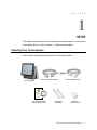
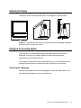
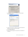
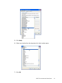
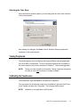
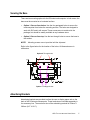
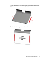
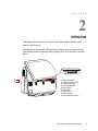
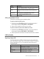
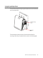
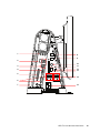
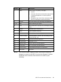
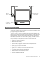
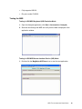
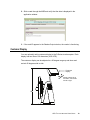
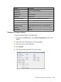
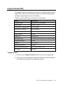
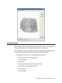
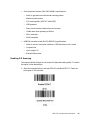
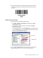
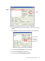
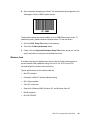
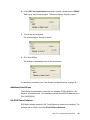
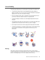
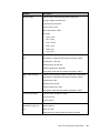
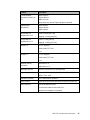
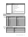
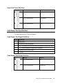
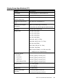
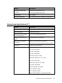
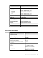
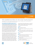
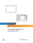
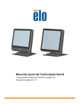
D-Series Touchcomputer User Guide
D-Series LCD Multi-function Touchcomputer
[Model D-Series]
Elo TouchSystems
D-Series Touchcomputer User Guide
Multi-function Touchcomputer
Revision B
P/N E674343
Elo TouchSystems
1-800-ELOTOUCH (1-800-356-8682)
www.elotouch.com
Copyright © 2009 Tyco Electronics. All Rights Reserved.
No part of this publication may be reproduced, transmitted, transcribed, stored in a
retrieval system, or translated into any language or computer language, in any
form or by any means, including, but not limited to, electronic, magnetic, optical,
chemical, manual, or otherwise without prior written permission of Elo
TouchSystems.
Disclaimer
The information in this document is subject to change without notice. Elo
TouchSystems makes no representations or warranties with respect to the
contents hereof, and specifically disclaims any implied warranties of
merchantability or fitness for a particular purpose. References in this publication to
Elo TouchSystems products or services do not imply that Elo TouchSystems
intends to make them available in all countries in which Elo TouchSystems
operates. Elo TouchSystems reserves the right to revise this publication and to
make changes from time to time in the content hereof without obligation of Elo
TouchSystems to notify any person of such revisions or changes.
Trademark Acknowledgments
Elo TouchSystems, IntelliTouch, SecureTouch, AccuTouch, MonitorMouse, TE
logo, and Tyco Electronics are trademarks. Other product names mentioned
herein may be trademarks or registered trademarks of their respective companies.
Tyco Electronics claims no interest in trademarks other than its own.
15D1 TOUCHCOMPUTER USER GUIDE
iii
Table of Contents
Chapter 1: Setup..................................................................................... 1
Unpacking Your Touchcomputer ....................................................................................................1
Adjusting the Display ......................................................................................................................2
Setting Up the Operating System.....................................................................................................2
Testing Peripherals...........................................................................................................................5
Calibrating the Touchscreen ............................................................................................................5
Securing the Base.............................................................................................................................7
Advertising Brackets........................................................................................................................7
Chapter 2: Operation.............................................................................. 9
On-Screen Display (OSD) .............................................................................................................10
LED Functionality .........................................................................................................................11
Using the Input/Output Panel.........................................................................................................13
Chapter 3: Options and Upgrades....................................................... 16
Adding Optional Peripherals..........................................................................................................16
Magnetic Stripe Reader (MSR) .....................................................................................................17
Customer Display...........................................................................................................................19
Fingerprint Reader (FPR) ..............................................................................................................21
Barcode Scanner ............................................................................................................................22
Third-Party Peripherals..................................................................................................................27
Chapter 4: Safety and Maintenance .................................................... 29
Safety .............................................................................................................................................29
Care and Handling .........................................................................................................................30
Recovering the Operating System .................................................................................................31
Chapter 5: Technical Specifications ................................................... 32
Touchcomputer Specifications.......................................................................................................32
Connector Specifications ...............................................................................................................36
Cash Drawer Port Specifications ...................................................................................................37
Display Screen Specifications........................................................................................................38
Environmental Specifications ........................................................................................................39
15D1 TOUCHCOMPUTER USER GUIDE
iv
Chapter 6: Technical Support.............................................................. 41
Technical Assistance......................................................................................................................41
Regulatory Information ..........................................................................43
Warranty ..................................................................................................46
Index ........................................................................................................48
15D1 TOUCHCOMPUTER USER GUIDE
v
C H A P T E R
1
SETUP
This chapter discusses how to set up and test your touchcomputer. For information
on peripheral options, refer to Chapter 3, “Options and Upgrades.”
Unpacking Your Touchcomputer
Check that the following items are present and in good condition:
Power cable US/Canada
Power cable Europe
Touchcomputer
Recovery DVD and
Quick Install Guide
Advertising
brackets
Optional
security screw
15D1 TOUCHCOMPUTER USER GUIDE
1
Adjusting the Display
The display screen can be adjusted from 0 to 60 degrees, as shown below.
CAUTION: To protect the LCD, be sure to hold the base when adjusting the display,
and take care to not touch the screen.
Setting Up the Operating System
The initial setup of the operating system takes approximately 5-10 minutes.
Additional time might be needed for different touchcomputer hardware
configurations and connected devices.
To set up the Windows OS for the touchcomputer, turn on the touchcomputer by
pressing the power button, and then follow the instructions on the screen.
Selecting the Language
Windows uses English as the default language in menus and dialog boxes. You
can change this language to suit your preferences.
15D1 TOUCHCOMPUTER USER GUIDE
2
1. Click Customize. The Regional and Language Options window appears.
Select the Languages tab.
2. If required, check the boxes for “Install files for complex script and right-to-left
languages” and “Install files for East Asian languages.”
3. Select the Regional Options tab.
4. Select your preferred language from the drop-down list in the Standards and
formats pane.
15D1 TOUCHCOMPUTER USER GUIDE
3
5. Click Apply.
6. Select your location from the drop-down list in the Locations pane.
7. Click OK.
15D1 TOUCHCOMPUTER USER GUIDE
4
Selecting the Time Zone
When the following window appears, you can change the time zone, date, and time
of the touchcomputer.
After making any changes, click Next to finish. Windows Setup completes the
installation of the touchcomputer.
Testing Peripherals
The touchcomputer can be configured with several different optional peripherals,
such as a MSR or cash drawer. To test an optional peripheral that is installed on
the touchcomputer, refer to the instructions in Chapter 3, “Options and Upgrades.”
NOTE:
Testing icons are located on the desktop. Testing a particular peripheral
can only be done after the device is properly installed.
Calibrating the Touchscreen
The touchscreen is pre-calibrated for accurate touch response.
If for any reason the touchscreen needs to be recalibrated, right-click the Elo icon
in the Taskbar and then click “Properties.” The following window opens.
NOTE:
Calibration is not applicable to APR models.
15D1 TOUCHCOMPUTER USER GUIDE
5
Click the Align button. This launches the calibration program. The window shown
below opens. Follow the instructions to calibrate the touchscreen.
15D1 TOUCHCOMPUTER USER GUIDE
6
Securing the Base
There are two mounting options for the D-Series touchcomputer. In both cases, the
base must be mounted on a horizontal surface.
•
Option 1: Secure from below. Use the four pretapped holes to secure the
touchcomputer from below the mounting surface. The holes are designed to
work with ISO metric m6 screws. These screws are not contained in the
package, but should be readily available at any hardware store.
•
Option 2: Secure from top. Use the two through holes to secure the base to
the surface.
NOTE:
Mounting screws are not provided with the shipment.
Refer to the figure below for the location of the holes. All dimensions are in
millimeters.
Option 2 Through holes
Option 1 Pretapped holes
Advertising Brackets
Advertising brackets are provided to allow the user to display paper ads on the
back of the D-Series touchcomputer. These brackets are included separately in
the accessory box. The maximum size of the advertising material is 220mm X
320mm (8.6” X 12.6”).
15D1 TOUCHCOMPUTER USER GUIDE
7
To install these brackets, simply push them onto the sides of the back door of the
D-Series touchcomputer, as shown in the figure below.
Then insert the advertising material as shown below.
15D1 TOUCHCOMPUTER USER GUIDE
8
C H A P T E R
2
OPERATION
This chapter describes how to control the On-Screen Display (OSD), power
buttons, and I/O panel.
All adjustments made to the OSD and power controls are automatically saved.
User settings remain unchanged after powering off/on or in the case of a power
failure.
34 5 6 7 8 9
1
2
1. HDD status LED
2. Computer power LED
3. Head power LED
4. Touch power LED
5. Menu button
6. Left button
7. Right button
8. Select button
9. Power ON/OFF button
15D1 TOUCHCOMPUTER USER GUIDE
9
On-Screen Display (OSD)
OSD Menu
1. To display the OSD Menu, press the Menu button.
Press the RIGHT button or LEFT button to toggle and the SELECT button to
select from the different OSD sub-menus and functions.
2. When the function you want to change is shown, press the SELECT button.
3. To adjust the value of the function:
4. Pressing the RIGHT button increases the value of the selected OSD control
option.
5. Pressing the LEFT button decreases the value of the selected OSD control
option.
The OSD provides the following settings.
Feature
Description
Auto adjust
Automatically adjusts system clock.
Brightness
Adjust brightness and contrast.
Image setting
•
Brightness: Adjusts the backlight of the monitor.
•
Contrast: Adjusts the maximum luminance level of the
monitor.
Adjusts H position, V position, clock, and phase.
•
H position: Moves the screen horizontally right and left (1 pixel
pitch increment).
•
V position: Moves the screen vertically up and down (1 line
increment).
•
Clock: Adjusts the ratio of dividing frequency of the dot clock.
•
Phase: Adjusts the phase of the dot clock.
Color
Sets color temperature (9300K, 7500K, 6500K, 5500K, or User
Preset).
OSD
Adjusts H position, V position, and OSD timeout.
•
H position: Adjusts the OSD menu screen position left or right.
•
V position: Adjusts the OSD menu screen position up or down.
•
Timeout: Adjusts the amount of time that the OSD menu is
displayed.
15D1 TOUCHCOMPUTER USER GUIDE
10
Feature
Description
Language
Changes language to English, French, Italian, German, Spanish,
Japanese, Simplified Chinese, or Traditional Chinese.
Recall
Sets color recall and recall defaults. Restores original factory
settings.
Miscellaneous
Adjusts sharpness, enables/disables DDCCI function.
•
Exit
Sharpness: Adjusts sharpness of video.
Exits the OSD.
OSD and Power Button Control
The OSD menu and power button are enabled by default.
To enable or disable the OSD function:
1. Simultaneously press Menu/Exit and the Left (<-) key for two seconds. A
window appears displaying OSD ENABLE or OSD DISABLE.
2. When the OSD is disabled, the OSD menu is not visible.
To enable or disable the power button (PWR) lock function:
1. Simultaneously press Menu/Exit and the Right (->) key for two seconds. A
window appears displaying PWR ENABLE or PWR DISABLE.
2. When the power button lock feature is activated, the power button is disabled.
LED Functionality
Base Power Status LED
The D-Series base has two LEDs that indicate the power status and hard drive
status. See the figure on page 9, item 1 for the location of this LED. The light can
be green, flashing green, red, or off. The table below shows LED state and
corresponding color.
LED Color to Observer
State
Off
No input power — Off mode
Red
Input power present, power switch off — Off mode
Flashes green
Input power present — Sleep mode
Green
Input power present — On mode
15D1 TOUCHCOMPUTER USER GUIDE
11
Head Power Status LED
The head power status is indicated by a different LED, which is located at the lower
edge of the head (#3 in figure on page 9).
LED Color to Observer
State
Off
No input power to head — Off mode
Red
Input power present, power switch off — Off mode
Amber
Input power present — Sleep mode
Green
Input power present — On mode
Touch Power Status LED
The touch power status is indicated by a separate LED located at the lower edge of
the head and to the right of the Head Power Status LED (#4 in figure on page 9).
This feature is available for AT and APR 7010.
LED Color to Observer
State
Off
No input power — Off mode
Red
Input power present, power switch off — Off mode
Amber
Input power present — Sleep mode
Green
Input power present — On mode
HDD Activity LED
Hard disk drive activity is indicated by a flashing LED on the base, just under the
computer power LED (#2 in the figure on page 9). Reading from and writing to the
disk causes the LED to flash.
LED Color to Observer
State
Off
No activity
Flashes green
Activity
15D1 TOUCHCOMPUTER USER GUIDE
12
Using the Input/Output Panel
To access the input/output (I/O) ports, open the cable cover door on the left side of
the unit, as shown below.
Optional security
screw
Opening for
cables
The touchcomputer provides a number of input and output interfaces for
connecting a wide variety of compliant devices as shown in the following figure.
15D1 TOUCHCOMPUTER USER GUIDE
13
1
8
9
2
3
4
10
11
12
13
5
14
6
7
15
15D1 TOUCHCOMPUTER USER GUIDE
14
Number
Port
Description
1
Audio
Audio in (left), out (center), mic (right)
•
Audio In
•
Audio Out: One 3.5mm stereo audio output jack for
connecting headphones or external powered
speakers
•
Microphone Input: One 3.5mm microphone input
jack for connecting an external microphone
2
Ethernet
One RJ45 Ethernet port providing LAN capabilities
3, 8, 9
USB
Seven USB 2.0 type A ports
4
VGA
One D-SUB VGA output port for connecting the display
head
5
Parallel
Standard 25-pin connector port
6
Serial
Three standard serial ports
7
PS/2 universal
Mouse (left) and keyboard (right)
8
Customer display
Customer display / USB 2.0; the max loading on this
port is 5VDC @ 1.5A
10
Printer power
One 24V DC printer power port
11
Compact flash
Standard CF port
12
Speaker power
Power switch for internal speakers
13
Cash drawer
RJ11, 6 position (12V/24V default)
14
Powered serial
Two powered serial ports, 5V default/12V
15
Main power
AC power
NOTE:
The customer display, fingerprint reader, and barcode scanner are
designed to connect to the USB 2.0 ports on the I/O panel. If all three
peripherals were connected, there would be four USB 2.0 ports
remaining.
15D1 TOUCHCOMPUTER USER GUIDE
15
C H A P T E R
3
OPTIONS AND UPGRADES
Adding Optional Peripherals
When adding a peripheral, complete installation and setup instructions are
provided with the field-installable kits. The following peripherals are available in
field-installable kits:
•
Magnetic stripe reader (MSR)
•
Customer display
•
Fingerprint reader (FPR)
•
Barcode scanner (1-D or omni-directional/2-D)
•
Wireless mini-PCI kit
•
Hard disk drive
•
Printer power cable
NOTE:
The peripherals described are all options that are purchased separately.
NOTE:
Testing software is available in the folder 15D1 Test Applications,
which is located on the desktop.
15D1 TOUCHCOMPUTER USER GUIDE
16
Magnetic stripe
reader (MSR)
Barcode
scanner
Fingerprint
reader (FPR)
Magnetic Stripe Reader (MSR)
You can add a magnetic stripe reader (MSR) to the D-Series touchcomputer using
a USB port located on the display head.
The MSR is a USB 2.0 device that reads all three data stripes on standard credit
cards or driver’s licenses conforming to ISO/ANSI standards. The MSR has foreign
language capability. The credit card is read by sliding the credit card forward or
backward through the MSR, stripe side toward the display. The MSR is powered
from the USB port; no external power is needed. The MSR features are:
•
Reads up to 3 tracks of information
•
Bidirectional swipe reading
•
Superior reading of high jitter, scratched, and worn MagStripe cards
•
Reliable for over 1,000,000 card swipes
•
Reads ISO7811, AAMVA, and most other card data formats
•
PC software makes configuration changes easy
•
Swipe speeds from 3 to 60 inches per second
•
Interfaces: USB-KB and USB-HID
15D1 TOUCHCOMPUTER USER GUIDE
17
•
Fully supports USB 2.0
•
Elo part number E145919
Testing the MSR
Testing in USB MSR Keyboard (KB) Emulation Mode
1. Open the Notepad application (click Start > Accessories > Notepad).
2. Slide the card through the MSR and verify that the data is displayed in the
application window.
Testing in USB MSR Human Interface Device (HID) Mode
1. Double-click the MagSwipe HID Demo icon to start the test application.
15D1 TOUCHCOMPUTER USER GUIDE
18
2. Slide a card through the MSR and verify that the data is displayed in the
application window.
3. If the card ID appears in the Reader Output window, the reader is functioning.
Customer Display
You can optionally add a customer display to the D-Series touchcomputer. Each
display has two lines of 20 characters (2x20 VFD).
The customer display can be adjusted to a 30-degree range up and down and
swivels 30 degrees side to side.
Customer
display
Display rotates 30° up
and down, and swivels
30° left to right
15D1 TOUCHCOMPUTER USER GUIDE
19
Feature
Description
Display type
Vacuum fluorescent display
Display color
Red
Display pattern
5 x 7 dot matrix
Brightness
350-600 cd/m
Characters available
95 alphanumeric & 32 international characters
Dot size (X x Y)
0.86 x 1.2 mm
Font size
5.5(W) x 10.5(H)
Character number
20 characters by 2 lines, for a 5 x 7 dot matrix font
Interface
USB
Part number
E326629
2
Testing the Customer Display
To test the customer display, follow these steps:
1. Double-click the VFD Test icon in the 15D1 Test Applications folder on the
desktop.
2. Select the correct COM port (refer to Device Manager).
3. Enter a line of text into the Text: field.
4. Click Initialize.
5. Verify that the device shows the line of text entered.
15D1 TOUCHCOMPUTER USER GUIDE
20
Fingerprint Reader (FPR)
The fingerprint reader is powered by the USB bus. The reader optically scans the
fingerprint when the user touches the glowing window. Optical technology gives
the highest quality fingerprint scans and reliability.
Fingerprint reader specifications are shown in the table below.
Feature
Specification
Fingerprint reader
DigitalPersona U.are.U 4000B
Power supply
5.0VDC +/- 0.25V
Current draw – scanning mode
190 mA (typical)
Current draw – idle mode
140 mA (typical)
Current draw – suspend mode
1.5 mA (typical)
Image resolution
512 dpi
Image color
8-bit gray level
Scan capture size
14.6mm (nominal width) x 18.1mm (nominal length)
Image capture speed
100 ms
USB type
1.0, 1.1, or 2.0
Operating temperature
0 to 40°C
Electrostatic discharge (ESD)
Up to 15kV mounted in case
Part number
E373639
Testing the FPR
1. Double-click the Fingerprint Reader Test icon to start the test application.
2. Place your finger on the fingerprint reader sensor and verify that the image of
your fingerprint is displayed on the application window.
15D1 TOUCHCOMPUTER USER GUIDE
21
Barcode Scanner
There are two types of optional USB barcode scanners: 1-D or omni-directional.
The barcode scanner is only an option if the speaker bar is present.
When a scanner is chosen, a USB-SSI (Simple Serial Interface) converter board is
included. Both barcode scanners are powered with the USB interface.
•
One-dimensional scanner (Elo P/N E946856) specifications:
•
Ability to generate 1-D scanning pattern
•
Low-cost solution
•
USB powered
•
Easy communication between host and scanner
•
Visible laser diode operating at 650nm
•
100+ scans/sec.
•
RoHS-compliant
15D1 TOUCHCOMPUTER USER GUIDE
22
•
•
Omni-directional scanner (Elo P/N E449881) specifications:
•
Ability to generate omni-directional scanning pattern
•
Maximum performance
•
2-D scanning ability (PDF417, MicroPDF)
•
USB powered
•
Easy communication between host and scanner
•
Visible laser diode operating at 650nm
•
600+ scans/sec.
•
RoHS compliant
USB-SSI converter board (Elo P/N E580321) specifications:
•
Ability to convert from serial interface to USB interface and vice versa.
•
Compact size
•
Input voltage: 5V
•
BuzzerWireless card
Enabling 2-D Scanning
The scanner default settings do not enable 2-D barcode reading ability. To enable
this option, follow these steps:
1. Scan the barcodes below to activate PDF417 and MicroPDF417. These are
both types of 2-D barcodes.
15D1 TOUCHCOMPUTER USER GUIDE
23
2. Now scan the barcode below to change the scanning pattern. Using this
scanning pattern allows you to read 2-D barcodes (you can still read 1-D
barcodes).
Testing the Barcode Scanner
1. Determine which port the barcode scanner is using:
a. Click Start > Settings > Control Panel (in Windows XP) or Start >
Control Panel (in Vista).
b. In the Windows Control Panel screen, double-click the Computer
Management application.
c. In Computer Management, select Device Manager. In the right pane, look
under the Ports section, and note the COM value (COM1, COM2, COM3,
and so on) of the USB-Serial Port object.
COM value
USB serial port
2. From the 15D1 Test Applications folder on the desktop, double-click the
Barcode Scanner Test icon to start the SSIContainer application.
15D1 TOUCHCOMPUTER USER GUIDE
24
Connect
button
Port
field
3. Change the Port field value to match the value you retrieved from the Device
Manager.
4. Click Connect. You should see the text “Connected” in the Messages field.
Param Number
Permanent
Param Change
New Value
5. In the box labeled Param Number, enter the value 238.
6. In the box labeled New Value, enter the value 1.
7. Check the box labeled Permanent Param Change.
15D1 TOUCHCOMPUTER USER GUIDE
25
8. Scan a barcode (sample given below). The scanned data should appear in the
“Messages” section of SSIContainer screen.
The barcode scanner also has the ability to run in USB-KB emulation mode. To
enable this option, please install the required drivers. To find the drivers:
1. Click the 15D1 Setup Files folder on the desktop.
2. Then click the Barcode Scanner folder.
3. Finally, click the Keyboard Emulation Setup Files folder, where you can find
setup instructions to complete the installation process.
Wireless Card
A wireless card can be installed as an option in the D-Series touchcomputer to
provide wireless LAN capabilities using a mini-PCI slot. A PCI to mini-PCI
converter board is provided in the wireless kit.
Typical specifications for the wireless card are:
•
Mini-PCI interface
•
Compliant to Mini-PCI industry-standard sizing
•
802.11b/g compliant
•
Two UFL connectors
•
Support for Windows 2000, Windows XP, and Windows Vista 32
•
RoHS compliant
•
Elo P/N E238795
15D1 TOUCHCOMPUTER USER GUIDE
26
Testing the Wireless Card
To test the wireless card:
1. From the desktop, click Start > Settings > Control Panel > Network
Connections (in Windows XP) or Start > Control Panel (in Vista).
2. Double-click the Wireless Network Connections icon to display available
networks and verify that the wireless network is detected.
NOTE:
If a wireless network needs to be initialized, please see your system
administrator.
Third-Party Peripherals
The D-Series touchcomputer includes two pre-configured ports for a printer and
cash drawer. These peripherals are not available from Elo TouchSystems.
Printer Port
A 24VDC printer power port to connect a compatible receipt printer is provided.
The 24VDC printer power cable is Elo P/N E337867.
Cash Drawer Port
We provide a standard RJ11 port to attach a cash drawer.
Testing the Cash Drawer Port
1. Connect the cash drawer to the touchcomputer using a cable with the correct
wiring definition.
15D1 TOUCHCOMPUTER USER GUIDE
27
2. In the 15D1 Test Applications folder on the desktop, double-click the FD2XX
Test icon to start the test program. The screen displays “Display is open.”
3. Turn off the test equipment.
The screen displays “Display is closed.”
4. Click Send 200ms.
The software automatically turns on the cash drawer.
For additional information, see “Cash Drawer Port Specifications” on page 36.
Additional Hard Drives
The D-Series touchcomputer comes with one standard 160GB (80GB for 15D1
Revision A) hard disk drive. You can add an optional second SATA hard disk drive
(Elo P/N E597623).
Elo POS Demo Software
POS demo software created by Elo TouchSystems is located on the desktop. The
software can be found in the folder Elo POS Demo Software.
15D1 TOUCHCOMPUTER USER GUIDE
28
C H A P T E R
4
SAFETY AND MAINTENANCE
Safety
Here is some important information on the proper setup and maintenance of your
touchcomputer.
•
To reduce the risk of electric shock, follow all safety notices and never open the
touchcomputer case.
•
Turn off the product before cleaning (refer to “Care and Handling” on page 30
for proper cleaning methods).
•
Your touchcomputer is equipped with a 3-wire, grounding power cord. The
power cord plug only fits into a grounded outlet. Do not attempt to fit the plug
into an outlet that has not been configured for this purpose. Do not use a
damaged power cord. Only use the power cord that comes with your Elo
TouchSystems touchcomputer. Use of an unauthorized power cord might
invalidate your warranty.
•
The slots located on the sides and top of the touchcomputer case are for
ventilation. Do not block or insert anything inside the ventilation slots.
•
It is important that your touchcomputer remains dry. Do not pour liquid into or
onto your touchcomputer. If your touchcomputer becomes wet, do not attempt
to repair it yourself.
15D1 TOUCHCOMPUTER USER GUIDE
29
Care and Handling
The following tips help keep your touchcomputer functioning at the optimal level.
•
To avoid risk of electric shock, do not disassemble the power adapter or
display unit cabinet. The unit is not user serviceable. Remember to unplug the
display unit from the power outlet before cleaning.
•
Do not use alcohol (methyl, ethyl, or isopropyl) or any strong solvent. Do not
use thinner or benzene, abrasive cleaners, or compressed air.
•
To clean the display unit cabinet, use a cloth lightly dampened with a mild
detergent.
•
Avoid getting liquids inside your touchcomputer. If liquid does get inside, have
a qualified service technician check it before you power it on again.
•
Do not wipe the screen with a cloth or sponge that could scratch the surface.
•
To clean the touchscreen, use window or glass cleaner. Put the cleaner on the
rag and wipe the touchscreen. Never apply the cleaner directly on the
touchscreen.
Warning
This product consists of devices that might contain mercury, which must be
recycled or disposed of in accordance with local, state, or federal laws. (Within this
system, the backlight lamps in the monitor display contain mercury.)
15D1 TOUCHCOMPUTER USER GUIDE
30
WEEE Directive
In the European Union, the Waste Electrical and Electronic Equipment (WEEE)
directive label shown to the left indicates that this product should not be disposed
of with household waste. It should be deposited at an appropriate facility for
recovery and recycling.
Recovering the Operating System
If for any reason the touchcomputer’s operating system and software need to be
recovered, insert the included recovery disk into an external DVD-ROM drive and
reboot the touchcomputer. Follow the on-screen instructions to complete recovery.
NOTE:
All data is deleted during the recovery process. The user must back up
files when necessary. Elo TouchSystems does not accept liability for lost
data or software.
NOTE:
The end user must adhere to Microsoft's Licensing Agreement.
15D1 TOUCHCOMPUTER USER GUIDE
31
C H A P T E R
5
TECHNICAL SPECIFICATIONS
Touchcomputer Specifications
NOTE:
Not all operating systems or options are supported in all regions. Please
contact your local Elo TouchSystems representative for details.
Feature
Processor for ESY15D1
Revision A
Description
Processor for ESY15D1
Revision B and
ESY17D1
Processor for ESY15D2
and ESY17D2
Intel Dual-Core Celeron E1500 2.2GHz 512K L2 Cache
800MHz FSB LGA775 Pkg
RAM
Two slots are available. Qualified vendor is Transcend.
Intel Celeron 430 1.8GHz 512K L2 Cache 800MHz FSB
LGA775 Pkg
Intel Core 2 Duo E8400 3.0GHz 6MB L2 Cache
1333MHz FSB LGA775 Pkg
Expandable up to 4GB max, DIMM DDR2-667(PC2-5400) or
DIMM DDR2-800(PC2-6400)
Dual channel
RAM for ESY15D1
Revision A
512MB 667MHz DDR2 standard on one slot
RAM for ESY15D1
Revision B and
ESY17D1
1GB 800MHz DDR2 standard on one slot
RAM for ESY15D2 and
ESY17D2
2GB 800MHz DDR2 standard on one slot
Northbridge
Intel G31
Southbridge
Intel ICH7
Audio
Azalia ALC883 Codec, 6 audio channels
15D1 TOUCHCOMPUTER USER GUIDE
32
Feature
Description
Video
Intel GMA 3100 (Vista Aero compatible)
Operating system
Microsoft Windows XP Professional SP3
Microsoft Windows Embedded for Point of Service (WEPOS)
Microsoft Windows Vista Business
Ports
7 x USB 2.0 ports
1 x 12V/24V default cash drawer port (jumper selectable)
3 x RS232 serial ports
2 x 5V default/12V powered RS232 serial ports (jumper
selectable)
2 x PS/2 (keyboard and mouse)
1 x Printer power port - 24VDC printer power port (24VDC @
2A; can accommodate 10.5mA spikes for a duration of 100ms)
Audio ports
1 x 3.5mm mic-in
1 x 3.5mm audio-in
1 x 3.5mm audio-out
Networking
1 x 10/100BASE-T Ethernet port (LAN RJ45)
BIOS
AMI
Real-time clock
Replaceable lithium-ion battery for clock
Storage
ESY15D1 Revision A: 1 x 2.5” SATA hard drive, 80GB
minimum
Optional 2nd 80GB hard drive available
ESY15D1 Revision B, ESY15D2, ESY17D1 and ESY17D2:
1 x 2.5” SATA hard drive, 160GB minimum
Optional 2nd 160GB hard drive available
1 Compact Flash type I (tested with Transcend, Apacer,
Kingston, and SanDisk)
15D1 TOUCHCOMPUTER USER GUIDE
33
Feature
Description
Power supply
Internal 12VDC universal-type power supply brick
AC input voltage: 100-240V AC
Input frequency: 50-60Hz
Input current: 2.5-5A
Max output power: 270W
DC output:
+3.3V / 5.0A
+5V / 16.0A
+12V / 12.0A
+24V / 2.3A
+5Vsb / 3A
-12V / 0.4A
Max. power rating for
15”
D-Series touchcomputer (without peripherals, receipt printer,
cash drawer, or powered serial ports connected: 145W
Cash drawer: 2.4W max
Receipt printer; 45.6W max
Powered serial ports: 24W max
Total power drawn with all possible peripherals: 228 W
Max. power rating for
17”
D-Series touchcomputer (without peripherals, receipt printer,
cash drawer, or powered serial ports connected: 160W
Cash drawer: 2.4W
Receipt printer; 45.6W
Powered serial ports: 24W
Total power drawn with all possible peripherals: 243W
Touch technologies
Acoustic Pulse Recognition (APR)
AccuTouch (AT)
IntelliTouch (IT)
Touchcomputer
dimensions (max.) for
15”
Width: 345 mm
Height: 288 mm
Depth: 212 mm
Dimensions vary with tilt angle and options selected
15D1 TOUCHCOMPUTER USER GUIDE
34
Feature
Description
Touchcomputer
dimensions (max.) for
17”
Width: 345 mm
Height: 288 mm
Depth: 212 mm
Dimensions vary with tilt angle and options selected
Shipping box
dimensions
Width: 450mm
Height: 475mm
Depth: 340mm
Weight without
peripherals for 15”
Actual: 10.03kg (22.1 lbs)
Weight without
peripherals for 17”
Actual: 11.79kg (26 lbs)
Display 15”
15.0 in. diagonal
Shipping: 12.16kg (26.8 lbs)
Shipping: 13.93kg (30.7 lbs)
Active matrix TFT LCD
4x3
Display 17”
17.0 in. diagonal
Active matrix TFT LCD
5x4
Optimal (native)
resolution
1024x768 for 15”
Backlight lamp life
Minimum 50,000 hours to half brightness
Agency approvals
UL/cUL, CE, BSMI, NOM, AR, CCC, EK, KCC, GOST-R,
RCM, C-Tick, VCCI
Speakers (internal)
Two 2-Watt/channel speakers
User controls
Power and user controls with lockout function for public use
Other features
User-accessible hard drive
1280x1024 for 17”
Touchscreen sealed to bezel and LCD
Security lock receptacle, Kensington
15D1 TOUCHCOMPUTER USER GUIDE
35
Feature
Description
Peripheral options and
upgrades
Magnetic stripe reader, 3 tracks
Customer display 2 x 20 VFD
Biometric fingerprint reader
Barcode scanner (1-D or omni/2-D)
Second 160GB hard drive
Wireless card
Printer power cable
24VDC PoweredUSB Adapter Cable (connect select 24VDC
PoweredUSB devices through the D-Series 24VDC printer
power port)
Connector Specifications
Serial Ports
Pin #
Standard Ports Signal Name
Powered Ports Signal Name
1
SER DCD
SER DCD
2
SER RXD
SER RXD
3
SER TXD
SER TXD
4
SER DTR
SER DTR
5
SER GND
SER GND
6
SER DSR
SER DSR
7
SER RTS
SER RTS
8
SER CTS
SER CTS
9
SER RI
5V(default)/ 12V
Printer Power Input Pin Definition
Pin #
Signal Name
1
+24V
2
NC
3
Ground
4
Flat
15D1 TOUCHCOMPUTER USER GUIDE
36
Serial Port Power Selection
J1/J2
Setting
Function
All pins open
No power
Pins 1-2 short/closed
5V (default)
Pins 2-3 short/closed
12V
Cash Drawer Port Specifications
The cash drawer port is 12/24V compatible.
Cash Drawer Port Signal Definition
Pin #
Signal Name
1
Frame ground
2
CD 1 drawer kick-out drive signal 1
3
SW ( + ) connected on the side of the open/closed detection switch on the drawer
4
L ( + ) +12V/24V (default) for drawer kick-out supplied
5
CD 2-drawer kick-out drive signal 2
6
( - ) Ground
Cash Drawer Port Power Selection
J3
Setting
Function
Pins 1-2 short/closed
12V
Pins 2-3 short/closed
24V (default)
15D1 TOUCHCOMPUTER USER GUIDE
37
Display Screen Specifications (15”)
Feature
Specification
LCD display
15.0-inch diagonal TFT active matrix LCD
Video input signal
Analog RGB (0.7Vp-p)
Data display channel (DDC)
function (plug & play)
DDC1, 2B compliant (EDID data only)
Display size (useful screen
area)
304.128mm (H) x 228.096mm (V)
Maximum touchcomputer
dimensions
288mm (H) x 345mm (W) x 212mm (D)
Pixel pitch
0.297mm (H) x 0.297mm (V)
Display mode
VGA 640 x 350 (70Hz)
* Dimensions vary with tilt angle and options selected
VGA 720 x 400 (70Hz)
VGA 640 x 480 (60Hz)
MAC 640 x 480 (66Hz)
VESA 640 x 480 (72 / 75Hz)
VESA 800 x 600 (56 / 60 / 72 / 75Hz)
MAC 832 x 624 (75Hz)
VESA 1024 x 768 (60 / 70 / 75Hz)
SUN 1024 x 768 (65Hz)
Note: If input fH>60kHz, or fV>75Hz, then OSD
displays an out of range warning.
Brightness (typical)
2
2
2
2
2
2
2
2
No touch
225 cd/m (typical); 170 cd/m (min.)
AccuTouch
200 cd/m (typical); 150 cd/m (min.)
IntelliTouch
APR (7000 and 7010)
Response time
225 cd/m (typical); 170 cd/m (min.)
225 cd/m (typical); 170 cd/m (min.)
Trise: 2.3 ms (typical)
Tfall: 6 ms (typical)
Display color
16.7 million colors
Vertical viewing angle
(up/down)
60° looking up typical at a CR=10
65° looking down typical at a CR=10
15D1 TOUCHCOMPUTER USER GUIDE
38
Feature
Specification
Horizontal viewing angle
(left/right)
70° looking left typical at a CR=10
Contrast ratio
700:1 (typical)
Optional touchscreens
AccuTouch, IntelliTouch, Acoustic Pulse Recognition
70° looking right typical at a CR=10
Display Screen Specifications (17”)
Feature
Specification
LCD display
17.0-inch diagonal TFT active matrix LCD
Video input signal
Analog RGB (0.7Vp-p)
Data display channel (DDC)
function (plug & play)
DDC1, 2B compliant (EDID data only)
Display size (useful screen
area)
337.920mm (H) x 270.336mm (V)
Maximum touchcomputer
dimensions
288mm (H) x 345mm (W) x 212mm (D)
Pixel pitch
0.264mm (H) x 0.264mm (V)
Display mode
VGA 640 x 350 (70Hz)
* Dimensions vary with tilt angle and options selected
VGA 720 x 400 (70Hz)
VGA 640 x 480 (60Hz)
MAC 640 x 480 (66Hz)
VESA 640 x 480 (72 / 75Hz)
VESA 800 x 600 (56 / 60 / 72 / 75Hz)
MAC 832 x 624 (75Hz)
VESA 1024 x 768 (60 / 70 / 75Hz)
SUN 1024 x 768 (65Hz)
SXGA 1280x1024 (60 / 75Hz)
SXGA 1152x864 (75Hz)
SXGA 1280x960 (60Hz)
Note: If input fH>60kHz, or fV>75Hz, then OSD
15D1 TOUCHCOMPUTER USER GUIDE
39
Feature
Specification
displays an out of range warning.
Brightness (typical)
2
2
2
2
2
2
2
2
No touch
300 cd/m (typical); 250 cd/m (min.)
AccuTouch
240 cd/m (typical); 192 cd/m (min.)
IntelliTouch
APR
270 cd/m (typical); 204 cd/m (min.)
270 cd/m (typical); 204 cd/m (min.)
Response time
Total: 5ms (Typical)
Display color
16.7 million colors
Vertical viewing angle
(up/down)
80° looking up typical at a CR=10
Horizontal viewing angle
(left/right)
80° looking left typical at a CR=10
Contrast ratio
1000:1 (typical)
Optional touchscreens
AccuTouch, IntelliTouch, Acoustic Pulse Recognition
80° looking down typical at a CR=10
80° looking right typical at a CR=10
Environmental Specifications
Feature
Specification
Temperature Ranges
Operating (independent of altitude)
0 to 35°C
Non-operating (independent of altitude)
-20 to 60°C
Humidity
Operating (noncondensing)
20 to 80%
Non-operating (38.7°C maximum wet bulb
temperature)
5 to 95%
Altitude
Operating
0 to + 12,000 feet [3,658m]
Equivalent to 14.7 to 10.1 psia
Non-operating
0 to + 40,000 feet [12,192m]
Equivalent to 14.7 to 4.4 psia
15D1 TOUCHCOMPUTER USER GUIDE
40
C H A P T E R
6
TECHNICAL SUPPORT
Technical Assistance
There are three methods to obtain contact information for technical assistance on
the touchcomputer:
•
The touchcomputer
•
The web
•
The phone
Using the Touchcomputer
You can access support information in System Properties by clicking the Support
Information button. You can get to System Properties by either of the following
methods:
•
Right-click My Computer and choose Properties.
or
•
Click the Start button, select Control Panel, and double-click the System
icon.
Using the Web
For online self-help, go to www.elotouch.com/go/websupport.
For technical support, go to www.elotouch.com/go/contactsupport.
For current Elo news, product updates, and announcements, or to register to
receive our Touchcomputer newsletter, go to www.elotouch.com/go/news.
15D1 TOUCHCOMPUTER USER GUIDE
41
Using the Phone
Call toll-free 1-800-ELO-TOUCH (1-800-356-8682).
15D1 TOUCHCOMPUTER USER GUIDE
42
REGULATORY INFORMATION
I. Electrical Safety Information
A) Compliance is required with respect to the voltage, frequency, and current
requirements indicated on the manufacturer’s label. Connection to a different
power source than those specified herein may result in improper operation,
damage to the equipment, invalidation of warranty, or a fire hazard if the
requirements are not followed.
B) There are no operator-serviceable parts inside this equipment. There are
hazardous voltages generated by this equipment which constitute a safety hazard.
Service should be provided only by a qualified service technician.
C) This equipment is provided with a detachable power cord which has an integral
safety ground wire intended for connection to a grounded safety outlet.
1) Do not substitute the cord with other than the provided approved type. Under
no circumstances use an adapter plug to connect to a 2-wire outlet as this
defeats the continuity of the grounding wire.
2) The equipment requires the use of the ground wire as a part of the safety
certification. Modification or misuse can provide a shock hazard that can result
in serious injury or death.
3) Contact a qualified electrician or the manufacturer if there are questions
about the installation prior to connecting the equipment to main power.
II. Emissions and Immunity Information
A) Notice to Users in the United States: This equipment has been tested and found
to comply with the limits for a Class B digital device, pursuant to Part 15 of FCC
Rules. These limits are designed to provide reasonable protection against harmful
interference in a residential or commercial installation. This equipment generates,
uses, and can radiate radio frequency energy, and if not installed and used in
accordance with the instructions, may cause harmful interference to radio
communications.
B) Notice to Users in Canada: This equipment complies with the Class B limits for
radio noise emissions from digital apparatus as established by the Radio
Interference Regulations of Industry Canada.
15D1 TOUCHCOMPUTER USER GUIDE
43
C) Notice to Users in the European Union: Use only the provided power cords and
interconnecting cabling provided with the equipment. Substitution of provided
cords and cabling may compromise electrical safety or CE Mark Certification for
emissions or immunity as required by the following standards: This Information
Technology Equipment (ITE) is required to have a CE Mark on the manufacturer’s
label which means that the equipment has been tested to the following Directives
and Standards:
This equipment has been tested to the requirements for the CE Mark as required
by EMC Directive 89/336/EEC indicated in European Standard EN 55022 Class B
and the Low Voltage Directive 73/23/EEC as indicated in European Standard EN
60950.
D) General Information to all Users: This equipment generates, uses, and can
radiate radio frequency energy. If not installed and used according to this manual,
the equipment may cause interference with radio and television communications.
There is, however, no guarantee that interference will not occur in any particular
installation due to site-specific factors.
1) In order to meet emission and immunity requirements, the user must
observe the following:
a) Use only the provided I/O cables to connect this digital device with any
computer.
b) To ensure compliance, use only the provided manufacturer’s approved
power cord.
c) The user is cautioned that changes or modifications to the equipment not
expressly approved by the party responsible for compliance could void the
user’s authority to operate the equipment.
2) If this equipment appears to cause interference with radio or television
reception, or any other device:
a) Verify as an emission source by turning the equipment off and on.
b) If you determine that this equipment is causing the interference, try to
correct the interference by using one or more of the following measures:
i) Move the digital device away from the affected receiver.
ii) Reposition (turn) the digital device with respect to the affected
receiver.
iii) Reorient the affected receiver’s antenna.
15D1 TOUCHCOMPUTER USER GUIDE
44
iv) Plug the digital device into a different AC outlet so the digital device
and the receiver are on different branch circuits.
v) Disconnect and remove any I/O cables that the digital device does
not use. (Unterminated I/O cables are a potential source of high RF
emission levels.)
vi) Plug the digital device into only a grounded outlet receptacle. Do not
use AC adapter plugs. (Removing or cutting the line cord ground may
increase RF emission levels and may also present a lethal shock
hazard to the user.)
vii) If you need additional help, consult your dealer, manufacturer, or an
experienced radio or television technician.
III. Agency Certifications
The following certifications have been issued for the monitor:
•
Argentina S-Mark
•
FCC
•
Russia PCT
•
Australia C-Tick
•
IMERC
•
Taiwan BSMI
•
CE
•
Japan VCCI
•
UL
•
China CCC
•
Korea EK/KCC
•
cUL
•
China RoHS
•
Mexico NOM
•
WEEE
15D1 TOUCHCOMPUTER USER GUIDE
45
WARRANTY
Except as otherwise stated herein or in an order acknowledgment delivered to
Buyer, Seller warrants to Buyer that the Product shall be free of defects in
materials and workmanship. With the exception of the negotiated warranty
periods; the warranty for the touchcomputer and components of the product is 3
years.
Seller makes no warranty regarding the model life of components. Seller’s
suppliers may at any time and from time to time make changes in the components
delivered as Products or components. Buyer shall notify Seller in writing promptly
(and in no case later than thirty (30) days after discovery) of the failure of any
Product to conform to the warranty set forth above; shall describe in commercially
reasonable detail in such notice the symptoms associated with such failure; and
shall provide to Seller the opportunity to inspect such Products as installed, if
possible. The notice must be received by Seller during the Warranty Period for
such product, unless otherwise directed in writing by the Seller. Within thirty (30)
days after submitting such notice, Buyer shall package the allegedly defective
Product in its original shipping carton(s) or a functional equivalent and shall ship to
Seller at Buyer’s expense and risk.
Within a reasonable time after receipt of the allegedly defective Product and
verification by Seller that the Product fails to meet the warranty set forth above,
Seller shall correct such failure by, at Seller’s options, either (i) modifying or
repairing the Product or (ii) replacing the Product. Such modification, repair, or
replacement and the return shipment of the Product with minimum insurance to
Buyer shall be at Seller’s expense. Buyer shall bear the risk of loss or damage in
transit, and may insure the Product. Buyer shall reimburse Seller for transportation
cost incurred for Product returned but not found by Seller to be defective.
Modification or repair, of Products may, at Seller’s option, take place either at
Seller’s facilities or at Buyer’s premises. If Seller is unable to modify, repair, or
replace a Product to conform to the warranty set forth above, then Seller shall, at
Seller’s option, either refund to Buyer or credit to Buyer’s account the purchase
price of the Product less depreciation calculated on a straight-line basis over
Seller’s stated Warranty Period.
15D1 TOUCHCOMPUTER USER GUIDE
46
THESE REMEDIES SHALL BE THE BUYER’S EXCLUSIVE REMEDIES FOR
BREACH OF WARRANTY. EXCEPT FOR THE EXPRESS WARRANTY SET
FORTH ABOVE, SELLER GRANTS NO OTHER WARRANTIES, EXPRESS OR
IMPLIED BY STATUTE OR OTHERWISE, REGARDING THE PRODUCTS,
THEIR FITNESS FOR ANY PURPOSE, THEIR QUALITY, THEIR
MERCHANTABILITY, THEIR NONINFRINGEMENT, OR OTHERWISE. NO
EMPLOYEE OF SELLER OR ANY OTHER PARTY IS AUTHORIZED TO MAKE
ANY WARRANTY FOR THE GOODS OTHER THAN THE WARRANTY SET
FORTH HEREIN. SELLER’S LIABILITY UNDER THE WARRANTY SHALL BE
LIMITED TO A REFUND OF THE PURCHASE PRICE OF THE PRODUCT. IN NO
EVENT SHALL SELLER BE LIABLE FOR THE COST OF PROCUREMENT OR
INSTALLATION OF SUBSTITUTE GOODS BY BUYER OR FOR ANY SPECIAL,
CONSEQUENTIAL, INDIRECT, OR INCIDENTAL DAMAGES.
Buyer assumes the risk and agrees to indemnify Seller against and hold Seller
harmless from all liability relating to (i) assessing the suitability for Buyer’s intended
use of the Products and of any system design or drawing and (ii) determining the
compliance of Buyer’s use of the Products with applicable laws, regulations, codes,
and standards. Buyer retains and accepts full responsibility for all warranty and
other claims relating to or arising from Buyer’s products, which include or
incorporate Products or components manufactured or supplied by Seller. Buyer is
solely responsible for any and all representations and warranties regarding the
Products made or authorized by Buyer. Buyer will indemnify Seller and hold Seller
harmless from any liability, claims, loss, cost, or expenses (including reasonable
attorney’s fees) attributable to Buyer’s products or representations or warranties
concerning same.
15D1 TOUCHCOMPUTER USER GUIDE
47
INDEX
address, Elo TouchSystems, 48
advertising brackets, 7
audio ports, description, 15
barcode scanner
enabling 2-D scanning, 23
overview, 22
specifications, 22
testing, 24
testing, 21
hard drives
adding additional, 28
LED activity, 12
head power status, 12
input/output (I/O) panel
accessing, 12
illustration, 13
base power status, 11
language selection, 2
base, securing, 7
LCD
adjusting, 2
specifications, 37
box contents, 1
brackets, advertising, 7
cables
included, 1
printer power, 27
calibration, 5
cash drawer port
description, 15
overview, 27
specifications, 36
testing, 27
certifications, 42
compact flash port, 15
contact information, 39
controls, location diagram, 9
customer display
overview, 19
port description, 15
specifications, 20
testing, 20
customer support, 39
display screen
adjusting, 2
specifications, 37
email, Elo TouchSystems, 48
enabling or disabling power, 11
environmental specifications, 38
Ethernet port, 15
fingerprint reader (FPR)
overview, 21
specifications, 21
LEDs
base, 11
hard drives, 12
head, 12
location diagram, 9
touch, 12
magnetic stripe reader (MSR)
overview, 17
specifications, 17
testing, 18
maintenance
care and handling, 29
software, 30
mounting options, 7
on-screen display (OSD)
enabling or disabling menu, 11
menu settings, 10
operating system
recovering, 30
setting up, 2
operation, 9
options, adding, 16
parallel ports, 15
peripherals
adding, 16
third-party, 27
phone number, Elo TouchSystems, 39, 48
ports
accessing, 12
15D1 TOUCHCOMPUTER USER GUIDE
48
audio, 15
cash drawer, 15
compact flash, 15
customer display, 15
Ethernet, 15
illustration, 13
parallel, 15
printer power, 15
PS/2 universal, 15
serial, 15
speaker, 15
USB, 15
VGA, 15
power
base, 11
enabling or disabling button lock, 11
printer power port
about, 27
cables, 27
description, 15
specifications, 35
PS/2 universal port, 15
receipt printer specifications, 27
regulatory information, 41
safety, 29
scanning, enabling 2-D, 23
serial ports
description, 15
specifications, 35, 36
setup
display screen, 2
language selection, 2
mounting options, 7
operating system, 2
time zone selection, 5
touchscreen calibration, 5
unpacking, 1
display screen, 37
environmental, 38
fingerprint reader, 21
hardware, 32
magnetic stripe reader, 17
printer power port, 35
receipt printer, 27
serial ports, 35, 36
technical, 32
wireless card, 26
speaker port, 15
technical specifications, 32
technical support, 39
third-party peripherals, 27
time zone selection, 5
touch power status, 12
touchscreen
calibrating, 5
care and handling, 29
upgrades, adding, 16
USB ports, 15
VGA port description, 15
warranty, 44
website, Elo TouchSystems, 39, 48
WEEE directive, 30
wireless card
overview, 26
specifications, 26
testing, 26
software
demo, 28
recovery, 30
specifications
barcode scanner, 22
cash drawer port, 36
connectors, 35
customer display, 20
15D1 TOUCHCOMPUTER USER GUIDE
49
www.elotouch.com
Get the latest...
•
Product information
•
Specifications
•
News on upcoming events
•
Press release
•
Software drivers
•
Touch Monitor Newsletter
Getting in Touch with Elo
To find out more about Elo’s extensive range of touch solutions, visit our Website at www.elotouch.com or
simply call the office nearest you:
Germany
Elo TouchSystems
301 Constitution Drive
Menlo Park, CA 94025
USA
Tyco Electronics Raychem GmbH
(Elo TouchSystems Division)
Finsinger Feld 1
D-85521 Ottobrunn
Germany
(800) ELO-TOUCH
(800) 356-8682
Tel 650-361-4800
Fax 650-361-4747
Tel +49 (0)(89) 60822-0
Fax +49(0)(89) 60822-180
[email protected]
[email protected]
Belgium
Tyco Electronics Raychem
N.V.
(Elo TouchSystems Division)
Diestsesteenweg 692
B-3010 Kessel-Lo
Belgium
Tel +32(0)(16)35 21 00
Fax +32(0)(16)35 21 01
[email protected]
Asia-Pacific
Sun Hamada Bldg. 2F
1-19-20 ShinYokohama
Kanagawa 222-0033
Japan
Tel +81(45)478-2161
Fax +81(45)478-2180
www.tps.co.jp
© 2008 Tyco Electronics Printed in USA
North America
50