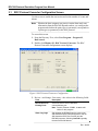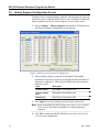
1
Form A6152 Part Number D301196X012 January 2009 ROC300 Protocol Emulation Program (for the ROC800-Series Remote Operations Controller) User Manual Remote Automation Solutions ROC300 Protocol Emulation Program User Manual Revision Tracking Sheet January 2009 This manual may be revised periodically to incorporate new or updated information. The revision date of each page appears at the bottom of the page opposite the page number. A change in revision date to any page also changes the date of the manual that appears on the front cover. Listed below is the revision date of each page (if applicable): Page All pages All pages All pages Initial release Revision Jan-09 Apr-08 Feb-06 Jul-04 NOTICE “Remote Automation Solutions (“RAS”), division of Emerson Process Management shall not be liable for technical or editorial errors in this manual or omissions from this manual. RAS MAKES NO WARRANTIES, EXPRESSED OR IMPLIED, INCLUDING THE IMPLIED WARRANTIES OF MERCHANTABILITY AND FITNESS FOR A PARTICULAR PURPOSE WITH RESPECT TO THIS MANUAL AND, IN NO EVENT SHALL RAS BE LIABLE FOR ANY INCIDENTAL, PUNITIVE, SPECIAL OR CONSEQUENTIAL DAMAGES INCLUDING, BUT NOT LIMITED TO, LOSS OF PRODUCTION, LOSS OF PROFITS, LOSS OF REVENUE OR USE AND COSTS INCURRED INCLUDING WITHOUT LIMITATION FOR CAPITAL, FUEL AND POWER, AND CLAIMS OF THIRD PARTIES. Bristol, Inc., Bristol Canada, BBI SA de CV and Emerson Process Management Ltd, Remote Automation Solutions division (UK), are wholly owned subsidiaries of Emerson Electric Co. doing business as Remote Automation Solutions (“RAS”), a division of Emerson Process Management. FloBoss, ROCLINK, Bristol, Bristol Babcock, ControlWave, TeleFlow and Helicoid are trademarks of RAS. AMS, PlantWeb and the PlantWeb logo are marks of Emerson Electric Co. The Emerson logo is a trademark and service mark of the Emerson Electric Co. All other trademarks are property of their respective owners. The contents of this publication are presented for informational purposes only. While every effort has been made to ensure informational accuracy, they are not to be construed as warranties or guarantees, express or implied, regarding the products or services described herein or their use or applicability. RAS reserves the right to modify or improve the designs or specifications of such products at any time without notice. All sales are governed by RAS’ terms and conditions which are available upon request. RAS does not assume responsibility for the selection, use or maintenance of any product. Responsibility for proper selection, use and maintenance of any RAS product remains solely with the purchaser and end-user.” © 2004-2009 Remote Automation Solutions, division of Emerson Process Management. All rights reserved. ii Rev. Jan-09 ROC300 Protocol Emulation Program User Manual Contents Page Chapter 1 – Introduction 1.1 1.2 1.3 Scope and Organization.......................................................................................................1 Product Overview.................................................................................................................1 1.2.1 Opcode Mappings by I/O Module Slot .....................................................................2 1.2.2 Events and Alarms Mapping ....................................................................................3 1.2.3 Point Type Conversions...........................................................................................3 1.2.4 Unsupported Parameters.........................................................................................4 Program Requirements ........................................................................................................4 Chapter 2 – Installation 2.1 4.3 Rev. Jan-09 11 ROC Protocol Converter Configuration Screen .................................................................12 History Segment Configuration Screen..............................................................................14 Saving the Configuration....................................................................................................15 Chapter 4 – Reference 4.1 4.2 7 Downloading the Program....................................................................................................7 Chapter 3 – Configuration 3.1 3.2 3.3 1 17 Supported Opcodes ...........................................................................................................17 Point Types 1 to 8, 10, 12 to 17, 19, 40 to 42 ....................................................................18 4.2.1 Point Type 1: Discrete Input...................................................................................18 4.2.2 Point Type 2: Discrete Output................................................................................21 4.2.3 Point Type 3: Analog Input.....................................................................................23 4.2.4 Point Type 4: Analog Output..................................................................................26 4.2.5 Point Type 5: Pulse Input.......................................................................................28 4.2.6 Point Type 6: PID ...................................................................................................30 4.2.7 Point Type 7: AGA Flow Parameters .....................................................................33 4.2.8 Point Type 10: AGA Flow Calculation Values........................................................38 4.2.9 Point Type 12: ROC Clock.....................................................................................40 4.2.10 Point Type 13: System Flags .................................................................................41 4.2.11 Point Type 14: Communication Ports ....................................................................43 4.2.12 Point Type 15: System Variables...........................................................................46 4.2.13 Point Type 16: FST Parameters ............................................................................48 4.2.14 Point Type 17: Soft Point Parameters....................................................................50 4.2.15 Point Type 19: Database Parameters....................................................................51 4.2.16 Point Type 40: Multi-Variable Sensor ....................................................................52 4.2.17 Point Type 41: Run Parameters (#1) .....................................................................57 4.2.18 Point Type 42: Run Parameters (#2) .....................................................................59 User Defined Point Type 69/76: Protocol Emulation Program Configuration ....................61 iii ROC300 Protocol Emulation Program User Manual [This page is intentionally left blank.] iv Rev. Jan-09 ROC300 Protocol Emulation Program User Manual Chapter 1 – Introduction This chapter describes the structure of this manual and presents an overview of the ROC300 Protocol Emulation program for the ROC800. 1.1 Scope and Organization This document serves as the user manual for the ROC300 Protocol Emulation program which is intended for use in a ROC800-Series Remote Operations Controller (“ROC800”). This manual describes how to download, install, and configure the ROC300 Protocol Emulation program (referred to as the “ROC300 Protocol program” or “the program” throughout the rest of this manual). You access and configure this program using ROCLINK™ 800 Configuration Software loaded on an IBMcompatible personal computer running Windows® 2000 (with Service Pack 2), XP, or Vista. The sections in this manual provide information in a sequence appropriate for first-time users. Once you become familiar with the procedures and the software, the manual becomes a reference tool. This manual has the following major sections: Section 1 – Introduction Section 2 – Installation Section 3 – Configuration Section 4 – Reference This manual assumes that you are familiar with the ROC800-Series and their configuration. For more information, refer to the following manuals: 1.2 ROC809 Remote Operations Controller Instruction Manual (Form A6116). ROC827 Remote Operation Controller Instruction Manual (Form A6175) ROCLINK 800 Configuration Software User Manual (Form A6121). Product Overview The ROC300 Protocol Emulation program enables a ROC800 to respond to requests from a ROC protocol host driver, used in ROC300-Series Remote Operations Controllers and FloBoss Flow Managers. The program converts ROC Plus protocol point types (used in the ROC800) to ROC Protocol point types and parameters, where applicable. The program also allows you to use specific opcodes to receive and send data from the host to the ROC800. Rev. Jan-09 1 ROC300 Protocol Emulation Program User Manual The ROC800 receives requests from a host on a specified communications port. The program converts both ROC Plus protocol point types and parameters to ROC Protocol point types and parameters and ROC Plus protocol Type, Logical, and Parameter (TLPs) to analogous ROC protocol TLPs. The program enables you to use specific opcodes to receive data from the host and to send data from the ROC800. You can access all 200 history points in the ROC800 using opcode 130. Once you have loaded this program and activated it for a given communications port (see Section 3.1), the ROC Plus Protocol communications are not available on that port. ROCLINK 800 will not connect and allow you to make configuration changes to that selected port. However, one way to have ROC Plus Protocol and the ROC300 Protocol Emulation program available on a given port is to write a supervisory FST program to control which protocol is active. For example, the FST command could be time-related to change the value of point type 69/76, logical 0, parameters 1 and 3 through 6. The parameter number indicates which comm port is active: 0 disables ROC300 Protocol Emulation while 1 enables it (see Section 4.3). Note: Be careful if you change the baud rate for the comm port used for ROC Protocol communications. (You define this using the System Configuration tab on the Device Information screen, accessed by selecting ROC > Information > Device Information screen.) If the host computer changes the baud rate of the port on which this program runs, this also changes the baud rate of any other ports on the same Baud Rate Generator. For further information on the ROC and ROC Plus protocols, refer to 1.2.1 ROC Plus Protocol User Manual (Form A6127), part number D301180X012. ROC Protocol User Manual (Form A4199), part number D301053X012. Opcode Mappings by I/O Module Slot The host computer uses opcode 130 (see Section 4.1) to poll for values of all 200 history points either by RAM Area 0 to 6 (which corresponds to History Segments 0 to 6) and point numbers 0 to 29 or by RAM Area 0 only and point numbers 0 to 199. When the host computer requests I/O module TLPs, the program assigns logicals based on the module slot in which the I/O module is located: 2 Rev. Jan-09 ROC300 Protocol Emulation Program User Manual Table 1. Opcode Mappings Based on I/O Module Slot ROC800 Module Position1, 3 1 2 3 4 5 (Unavailable; reserved for System AIs) 6 7 8 9 Logical Range2 (Maximum) 0 to 15 16 to 31 32 to 47 48 to 63 64 to 79 80 to 95 96 to 111 112 to 127 128 to 143 1 Slots 1 to 4 and slots 6 to 9 (with the exception of slot 5) are available. Logical ranges may change in future releases. 3 Table 1 assumes 16 points for each ROC800 module position. 2 1.2.2 Events and Alarms Mapping Whether the host computer can process certain alarm and event information from the ROC800 depends on how you configure this program and if the point type (or parameter) corresponds to a point type (or parameter) in the ROC Protocol. The ROC Protocol supports 240 alarms and 240 events. ROC800 can store up to 450 alarms and 450 events. During configuration (see Section 3.1) you indicate whether the program retains only the last 240 alarms or events or the full 450 alarms or events. Note: 1.2.3 The program always sends system events (such as warm starts or cold starts) to the host, since these events have the same format in both the ROC and ROC Plus protocols. Point Type Conversions The program converts any ROC800 point type that can be converted to a ROC protocol, as shown in the following table. As appropriate for the point type, the program converts parameter numbers as well. Table 2. ROC800 Point Type Conversions ROC800 Point Type 91 – System Variables 95 – Communication Ports 96 – FST Parameters 98 – Soft Point Parameters 99 – Configurable Opcode Table 101 – Discrete Inputs Rev. Jan-09 Converted to ROC Protocol Point Type 15 14 16 17 0 1 3 ROC300 Protocol Emulation Program User Manual ROC800 Point Type 102 – Discrete Outputs 103 – Analog Inputs 104 – Analog Outputs 105 – Pulse Inputs 106 – RTD 107 – Thermocouple 108 – Multi-Variable Sensor 109 – System Analog Inputs 110 – PID Control Parameters 112 – Station Parameters 113 – Orifice Meter Run Configuration 114 – Orifice Meter Run Values 115 – Turbine Meter Run Configuration 116 – Turbine Meter Run Values 136 – ROC Clock 1.2.4 Converted to ROC Protocol Point Type 2 3 4 5 3 3 40 3 6 7 or 41 7 or 41 41 or 42 7 41 or 42 12 Unsupported Parameters The program cannot support some parameters. If the host tries to access one of these unsupported parameters, the program may or may not send back an error, depending on the circumstances. The program has implemented the following rules to handle these parameters. These rules also apply when the Read-Only and Read-Write statuses don’t match. Table 3. Unsupported Parameter Handling If ROC Protocol Parameter is… Read-Only And ROC Plus Parameter is… Not Supported Read-Only Read-Only Read-Write Read-Only Read-Write Not Supported Read-Write Read-Write Read-Only Read-Write 1.3 Then Action on Read is… Return 0 or other appropriate default Return actual value Return actual value Return 0 or other appropriate default Return actual value Return actual value Then Action on Write is… Error 105 Error 105 Error 105 No error Error 105 No error Program Requirements Two versions of the program are provided. The versions use different point types, but are identical in function. Only one program using a specific point type will run on the ROC at any given time. Load the program version which uses a point type set that does not conflict with programs currently running on the ROC. 4 Rev. Jan-09 ROC300 Protocol Emulation Program User Manual Program specifics include: File Name Target Unit/ Version User Defined Point (UDP) Flash Used (in bytes) SRAM Used (in bytes) DRAM Used (in bytes) ROCKLINK 800 Version Display Number ROCProtocol_69_v124.tar ROC800 2.10 69 60,416 130 155,648 1.80 11 ROCProtocol_76_v124.tar ROC800 2.10 76 60,416 130 155,648 1.80 11 Note: You must connect a PC to the ROC800’s LOI port before starting the download. Also, display #11 must be available for this program’s use. For information on viewing the memory allocation of user programs, refer to the ROCLINK 800 Configuration Software User Manual (Form A6121). Rev. Jan-09 5 ROC300 Protocol Emulation Program User Manual [This page is intentionally left blank.] 6 Rev. Jan-09 ROC300 Protocol Emulation Program User Manual Chapter 2 – Installation This section provides instructions for installing the ROC300 Protocol Emulation program into the Flash memory on the ROC800. Read Section 1.3 of this manual for program requirements. 2.1 Downloading the Program This section provides instructions for installing the program into the Flash memory on the ROC800. Note: This manual shows the installation of RocProtocol_76_v124.tar. Choose the program version that uses point types which do not conflict with programs currently installed on the ROC. To download the program using ROCLINK 800 software: 1. Connect the ROC to your computer using the LOI port. 2. Start and logon to ROCLINK 800. 3. Select Utilities > User Program Administrator from the ROCLINK menu bar. The User Program Administrator screen displays (see Figure 1): Figure 1. User Program Administrator Rev. Jan-09 7 ROC300 Protocol Emulation Program User Manual 4. Select any empty program number into which to download the program. 5. Click Browse in the Download User Program File frame. The Select User Program File screen displays (see Figure 2). 6. Select the path and user program file to download from the CD-ROM. (Program files are typically located in the Program Files folder on the CD-ROM). As Figure 2 shows, the screen lists all valid user program files with the .TAR extension: Figure 2. Select User Program File 7. Click Open to select the program file. The User Program Administrator screen displays. As shown in Figure 3, note that the Download User Program File frame identifies the selected program and that the Download & Start button is active: 8 Rev. Jan-09 ROC300 Protocol Emulation Program User Manual Figure 3. User Program Administrator 8. Click Download & Start to begin loading the selected programs. The following message displays: Figure 4. Confirm Download 9. Click Yes to begin the download. When the download completes the following message displays: Figure 5. ROCLINK 800 Download Confirmation 10. Click OK. The User Program Administrator screen displays (see Figure 6). Note that: Rev. Jan-09 The Device User Program Environment frame reflects the use of system memory. The User Programs Installed in Device frame identifies the installed program(s). 9 ROC300 Protocol Emulation Program User Manual Figure 6. User Program Administrator 11. Click Close. The ROCLINK 800 screen displays and the download is complete. 12. Proceed to Section 3 to configure the program. 10 Rev. Jan-09 ROC300 Protocol Emulation Program User Manual Chapter 3 – Configuration After you have loaded the ROC300 Protocol Emulation program on the ROC800, you configure the program using one ROCLINK 800 screen (History Segment Configuration) and a program-specific screen (ROC Protocol Converter). Use the program-specific ROC Protocol Converter screen to enable the conversion and set the number of events and alarms captured. Use ROCLINK 800’s History Segment Configuration screen to configure history segments for the program. You can access the program-specific screen from the main ROCLINK 800 screen: Figure 7. ROCLINK 800 Rev. Jan-09 11 ROC300 Protocol Emulation Program User Manual 3.1 ROC Protocol Converter Configuration Screen Use this screen to enable the conversion and set the number of events and alarms. Note: Whether the host computer can process certain alarm and event information from the ROC800 depends on how you configure the program and whether the point type (or parameter) corresponds to a point type (or parameter) in the ROC protocol. To access this screen: 1. From the Directory Tree, select User Program > Program #1, RocProtocol. 2. Double-click Display #11, ROC Protocol Converter. The ROC Protocol Converter configuration screen displays: Figure 8. ROC Protocol Converter Configuration 3. Review—and change, if necessary—the values in the following fields: Field Description ROC Protocol On Existing Ports Check one box to select a ROC800 communications port. Note: Port #2, Ethernet COMM1, is not a valid choice for this program. Alarm Log Logic 12 Sets whether the ROC800 logs the most recent 240 alarms the ROC Protocol supports or the full 450 alarms the ROC Plus Protocol (and the ROC800) supports. Selecting Last 240 logs only the most recent 240 alarms. Rev. Jan-09 ROC300 Protocol Emulation Program User Manual Field Description Note: If you select All 450, the ROC800 uses a ROC Plus Protocol TLP for any alarms without a ROC Protocol equivalent. Event Log Logic Sets whether the ROC800 logs the most recent 240 events the ROC Protocol supports or the full 450 events the ROC Plus Protocol (and the ROC800) supports. Selecting Last 240 logs only the most recent 240 events. Note: If you select All 450, the ROC800 uses a ROC Plus Protocol TLP for any events without a ROC Protocol equivalent. IO Addressing Logic Sets whether the ROC800 exclusively uses modules with 16 points or if the program needs verify the number of points used for each module. Valid values are always 16 slots modules or 8 or 16 slots from Sys Param 50. 4. Click Apply to save any changes you have made to this screen. 5. Click OK to return to the ROCLINK 800 screen. Proceed to Section 3.2 to configure ROC800 history segments for use with this program. Rev. Jan-09 13 ROC300 Protocol Emulation Program User Manual 3.2 History Segment Configuration Screen Use this screen to configure history segments. The program can access all 200 history points in the ROC800, but you need to configure the ROC800 history segments specifically for the program. To access this screen: 1. Select Configure > History Segments from the ROCLINK menu bar. The History Segment Configuration screen displays: Figure 9. ROC Protocol Converter Configuration 2. Allocate history points to segments 01 through 07 (allocating a maximum of 30 points to segments 01 through 06 and a maximum of 20 points to segment 07). Ensure that the following fields contain the following values: Field Description Periodic Entries Enter 840 for each segment used. Periodic Sample Rate Enter 60 for each segment used. Daily Entries Enter 35 for each segment used. 3. Click Apply to save any changes you have made to this screen. Note: Refer to the ROCLINK 800 Configuration Software User Manual (Form A6121) for further information on configuring history segments. 4. Click OK to return to the ROCLINK 800 screen. Proceed to Section 3.3 to save the configuration. 14 Rev. Jan-09 ROC300 Protocol Emulation Program User Manual 3.3 Saving the Configuration Whenever you modify or change the configuration, it is a good practice to save the final configuration to memory. To save the configuration: 1. Select ROC > Flags. The Flags screen displays: Figure 10. Flags screen 2. Click Save Configuration. A verification message displays: Figure 11. Perform screen 3. Click Yes to begin the save process. The Status field on the Flags screen displays In Progress. When the process ends, the Status field on the Flags screen displays Completed. 4. Click Update on the Flags screen. This completes the process of saving your new configuration. Rev. Jan-09 15 ROC300 Protocol Emulation Program User Manual [This page is intentionally left blank.] 16 Rev. Jan-09 ROC300 Protocol Emulation Program User Manual Chapter 4 – Reference This section provides tables of information on the point types and parameters the ROC300 Protocol Emulation program uses: 4.1 Supported Opcodes. Point Types. User Defined Point Types. Supported Opcodes The ROC300 Protocol Emulation program supports the following opcodes: Table 4. Summary of Supported Opcodes Opcode 0 6 7 8 10 11 103 120 121 122 130 165 167 171 180 181 255 Rev. Jan-09 Description Send general update such as I/O update, gas flows, and control loop status. Send ROC configuration Send current time and date. Set new time and date. Send data from configurable opcode tables. Set data in configurable opcode tables. Send system information such as on and off times, manual and automatic alarm status, firmware version, and current time and date. Send pointers for alarm, event, and history logs. Send specified number of alarms starting at specified alarm pointer. Send specified number of events starting at specified event pointer. Send archived hourly and daily data for specified history point starting at specified history pointer. Read history point configuration. Note: Writing history configuration is not supported. Send specified contiguous block of parameters. Set parameters for specified point. Send specified parameters. Set specified parameters. Error messages transmitted by ROC in response to a request with invalid parameters or format. 17 ROC300 Protocol Emulation Program User Manual 4.2 Point Types 1 to 8, 10, 12 to 17, 19, 40 to 42 The following is a list of ROC300 point types and the corresponding mapping to the ROC800 running this program. Note: This program does not support point types 9, 11, 18, 20 to 39, or 44 to 59. 4.2.1 Point Type 1: Discrete Input Point Type 1: Discrete Input Parm # ReadWrite Data Type Length 0 R/W AC 10 1 R/W UINT 8 2 R/W 3 R/W ROC800 Point Type ROC800 Parameter Point Tag Identification 101 0 1 Filter N/A N/A UINT 8 1 Status 101 3 Full BIN 1 Modes 101 1 Full Bit 6 – RBX on Set 0 = Disabled on Set 1= RBX on Set 101 11 Full Bit 5 – RBX on Clear 0 = Disabled 1 = RBX on Clear 101 10 Full Bit 4 – Alarm Enable 0 = Disabled 1 = Log Alarms 101 9 Full Bit 3 – TDI Enable (ROC300-series and FloBoss 407) 0 = Disabled 1 = TDI Active N/A N/A Description Support Full None – returns 3 Bit 7 – Manual Mode 0 = Normal Scan 1 = Scan Disabled Rev. Jan-09 None – returns 0 18 ROC300 Protocol Emulation Program User Manual Point Type 1: Discrete Input Parm # ReadWrite Data Type Length 3 (cont’d) ROC800 Point Type ROC800 Parameter Bit 2 – Filter Interval 0 = 250 ms (50 ms for built-in DI) – ROC300series & FloBoss 407 0 = 100 ms – FloBoss 500-series, FloBoss 103, & RegFlo 1 = 15 seconds (3 sec for built-in DI) N/A N/A Bit 1 – Latch Enable 0 = Disable 1 = Enable 101 5 Full Bit 0 – Invert Enable 0 = Disabled 1 = Enable 101 4 Full Alarm Code Bit 7 – Manual Mode Bit 6 – Not Used Bit 5 – Status Change Bit 4 – TDI Rate Alarm Bit 3 – TDI High Alarm Bit 2 – TDI High High Alarm Bit 1 – TDI Low Alarm Bit 0 – TDI Low Low Alarm 101 12 Partial – Bits 7 and 5 are supported; all others are set to 0 Description Support None – returns 0 4 R/O BIN 1 5 R/W UINT 32 4 Accumulated Value 101 6 Full 6 R/W UINT 32 4 On Counter 101 7 Partial – ROC800 On Time in seconds (FLP) converts to 50 ms periods (UINT32) 7 R/W UINT 32 4 Off Counter 101 8 Partial – ROC800 Off Time in seconds (FLP) converts to 50 ms periods (UINT32) 8 R/W INT 16 2 0% Pulse Width N/A N/A None – returns 0 9 R/W INT 16 2 100% Pulse Width N/A N/A None – returns 0 10 R/W UINT 16 2 Max time between pulses / Max Count N/A N/A None – returns 0 Rev. Jan-09 19 ROC300 Protocol Emulation Program User Manual Point Type 1: Discrete Input 20 Parm # ReadWrite Data Type Length 11 R/W AC 10 12 R/W UINT 16 13 R/W 14 ROC800 Point Type ROC800 Parameter Units N/A N/A None – returns 0 2 Scan Period N/A N/A None – returns 0 FLP 4 Low Reading (Zero) EU N/A N/A None – returns 0 R/W FLP 4 High Reading (Span) EU N/A N/A None – returns 0 15 R/W FLP 4 Low Alarm EU N/A N/A None – returns 0 16 R/W FLP 4 High Alarm EU N/A N/A None – returns 0 17 R/W FLP 4 Low Low Alarm EU N/A N/A None – returns 0 18 R/W FLP 4 Hi Hi Alarm EU N/A N/A None – returns 0 19 R/W FLP 4 Rate Alarm EU N/A N/A None – returns 0 20 R/W FLP 4 Alarm Deadband N/A N/A None – returns 0 21 R/W FLP 4 EU Value N/A N/A None – returns 0 22 R/O UINT 16 2 TDI Count N/A N/A None – returns 0 Description Support Rev. Jan-09 ROC300 Protocol Emulation Program User Manual 4.2.2 Point Type 2: Discrete Output Point Type 2: Discrete Output Parm # ReadWrite Data Type ROC800 Point Type ROC800 Parameter 0 R/W AC 10 Point Tag Identification 102 0 Full 1 R/W UINT 16 2 Time On 102 14 Partial – ROC800 Time On in seconds (FLP) converts to 50 ms periods (UINT16) 2 R/O UINT 8 1 Not Used N/A N/A None – returns 0 3 R/W UINT 8 1 Status 102 8, 21, or 24 Full – When reading, uses param 24 (Physical). When writing, uses 8 (Auto) or 21 (Manual) depending on mode. 4 R/W BIN 1 Mode 102 2 Partial – Normal Scan maps to Automatic in the ROC800 and Scan Disabled maps to Disabled in the ROC800 N/A N/A Bit 4 – Clear on Reset 0 = Disabled – Retain Last Status 1 = Enabled 102 7 Partial – ROC800 actually uses Failsafe value rather than clear Bit 3 – TDO Enabled 0 = Disabled 1 = Enabled 102 13 Full Bit 2 – Do not set this bit N/A N/A None Bit 1 – Toggle 0 = Disabled 1 = Enabled 102 12 Full Bit 0 – Momentary 0 = Disabled 1 = Enabled 102 10 and 11 Full Length Description Bit 7 – Manual Mode 0 = Normal Scan 1 = Scan Disabled Bit 6 – Not Used Support Full Bit 5 – Not Used Rev. Jan-09 21 ROC300 Protocol Emulation Program User Manual Point Type 2: Discrete Output Parm # ReadWrite Data Type 5 R/O BIN Length Description ROC800 Point Type ROC800 Parameter 1 Alarm Code: 102 6 Partial – Scanning Disabled alarm in ROC800 maps to bit 7, manual alarm in ROC800 not mapped Bit 7 – Manual Mode Bits 6-0 – Not Used 22 Support 6 R/W UINT 32 4 Accumulated Value 102 9 Full 7 R/W AC 10 Units 102 1 Full 8 R/W UINT 16 2 Cycle Time 102 15 Partial – ROC800 Cycle Time in seconds (FLP) converts to 50 ms periods (UINT16) 9 R/W INT 16 2 0% Count 102 16 Partial – ROC800 Low Reading Time in seconds (FLP) converts to 50 ms periods (INT16) 10 R/W INT 16 2 100% Count 102 17 Partial – ROC800 High Reading Time in seconds (FLP) converts to 50 ms periods (INT16) 11 R/W FLP 4 Low Reading EU 102 18 Full 12 R/W FLP 4 High Reading EU 102 19 Full 13 R/W FLP 4 EU Value 102 20 Full Rev. Jan-09 ROC300 Protocol Emulation Program User Manual 4.2.3 Point Type 3: Analog Input Point Type 3: Analog Input Parm # ReadWrite Data Type Length 0 R/W AC 10 1 R/W AC 2 R/W 3 4 ROC800 Point Type ROC800 Parameter Point Tag Identification 103/106/107/109 0/0/0/0 Full 10 Units 103/106/107/109 1/1/1/1 Full UINT16 2 Scan Period 103/106/107/109 3/3/5/3 Partial – ROC800 Scan Period in seconds (FLP) converts to 50 ms periods (UINT16) R/W UINT16 2 Filter 103/106/107/109 5/5/7/5 Full R/O INT 16 2 Adjusted A/D 0% 103/106/107/109 8/9/NA/8 Description Support Partial – This parameter is R/O in the ROC800 and can only be modified through the calibration routine. Not supported for ROC800 Thermocouple (Pt Type 107) 5 R/O INT 16 2 Adjusted A/D 100% 103/106/107/109 12/13/NA/9 Partial – This parameter is R/O in the ROC800 and can only be modified through the calibration routine. Not supported for ROC800 Thermocouple (Pt Type 107) 6 R/W FLP 4 Low Reading EU 103/106/107/109 13/14/NA/10 Full for ROC800 Point types 103, 106 and 109 Not supported for ROC800 Thermocouple (Pt Type 107) 7 R/W FLP 4 High Reading EU 103/106/107/109 17/18/NA/11 Full for ROC800 Point types 103, 106 and 109. Not supported for ROC800 Thermocouple (Pt Type 107) 8 R/W FLP 4 Low Alarm EU 103/106/107/109 24/25/11/15 Full 9 R/W FLP 4 High Alarm EU 103/106/107/109 25/26/12/16 Full 10 R/W FLP 4 Low Low Alarm EU 103/106/107/109 23/24/10/14 Full 11 R/W FLP 4 Hi Hi Alarm EU 103/106/107/109 26/27/13/17 Full Rev. Jan-09 23 ROC300 Protocol Emulation Program User Manual Point Type 3: Analog Input Parm # ReadWrite Data Type Length 12 R/W FLP 4 13 R/W FLP 14 R/W 15 R/W ROC800 Point Type ROC800 Parameter Rate Alarm EU 103/106/107/109 27/28/14/18 Full 4 Alarm Deadband 103/106/107/109 28/29/15/19 Full FLP 4 Filtered EUs 103/106/107/109 21/22/9/12 Full BIN 1 Mode 103/106/107/109 2/2/2/2 Full Bit 6 – RBX on Set 0 = Disabled 1 = Active 103/106/107/109 31/32/18/22 Full Bit 5 – RBX on Clear 0 = Disabled 1 = Active 103/106/107/109 30/31/17/21 Full Bit 4 – ALM Enable 0 = Disabled 1 = Log Alarm 103/106/107/109 29/30/16/20 Full Bit 3 – Average Enable (for ROCs & FloBoss) 0 = Disabled 1 = Average Enable 103/106/107/109 6/6/8/6 Full Bit 2 – Temp Comp Enable 0 = Disabled 1 = Temp Comp Enable N/A N/A 103/106/107/109 22/23/NA/13 Description Support Bit 7 – Manual Mode 0 = Normal Scan 1 = Manual Scan Bit 1 – Clipping 0 = Disable 1 = Clipping Enable Bit 0 – Not Used 24 None – returns 0 Full for ROC800 Point types 103, 106 and 109. Not supported for ROC800 Thermocouple (Pt Type 107) N/A N/A Full Rev. Jan-09 ROC300 Protocol Emulation Program User Manual Point Type 3: Analog Input Parm # ReadWrite Data Type Length Description ROC800 Point Type ROC800 Parameter 16 R/O BIN 1 Alarm Code 103/106/107/109 32/33/19/23 103/106/107/109 7/8/NA/7 Support Full Bit 7 – Manual Mode Bit 6 – Point Fail Bit 5 – Not Used Bit 4 – Rate Alarm Bit 3 – High High Alarm Bit 2 – High Alarm Bit 1 – Low Low Alarm Bit 0 – Low Alarm 17 R/O UINT 16 2 Raw A/D Input Full for ROC800 Point types 103, 106 and 109, Not supported for ROC800 Thermocouple (Pt Type 107) 18 Rev. Jan-09 R/O INT 16 2 Actual Scan Time 103/106/107/109 4/4/6/4 Partial – ROC800 Actual Scan Time in seconds (FLP) converts to 50 ms periods (INT16) 25 ROC300 Protocol Emulation Program User Manual 4.2.4 Point Type 4: Analog Output Point Type 4: Analog Output Parm # ReadWrite Data Type Length 0 R/W AC 10 1 R/W AC 2 R/W 3 ROC800 Point Type ROC800 Parameter Point Tag Identification 104 0 Full 10 Units 104 1 Full INT 16 2 Adjusted D/A 0% 104 8 Full R/W INT 16 2 Adjusted D/A 100% 104 9 Full 4 R/W FLP 4 Low Reading EU 104 10 Full 5 R/W FLP 4 High Reading EU 104 11 Full 6 R/W FLP 4 Value in EUs 104 12,14, or 16 Full – When reading, use param 16 (Physical). When writing, use 12 (Auto) or 14 (Manual) depending on mode. 7 R/W BIN 1 Mode 104 2 Partial – Normal Scan maps to Automatic in the ROC800 and Scan Disabled maps to Disabled in the ROC800 Bit 6 – RBX on Set 0 = Disabled 1 = Active 104 5 Full Bit 5 – RBX on Clear 0 = Disabled 1 = Active 104 4 Full Bit 4 – ALM Enable 0 = Disabled 1 = Log Alarms 104 3 Full Bit 3 – Clear on Reset 0 = Disabled 1 = Enable 104 7 Partial – ROC800 actually uses Failsafe value rather than clear Bit 2-0 – Unused N/A N/A Description Bit 7 – Manual Mode 0 = Normal Scan 1 = Manual Scan 26 Support Full Rev. Jan-09 ROC300 Protocol Emulation Program User Manual Point Type 4: Analog Output Parm # ReadWrite Data Type Length Description ROC800 Point Type ROC800 Parameter 8 R/O BIN 1 Alarm Code: 104 6 Partial – Scanning Disabled alarm in ROC800 maps to bit 7, manual alarm in ROC800 is not mapped. 104 13 Full Bit 7 = Manual Mode Bit 6 = Point Fail Support Bits 5 through 0 – Not Used 9 Rev. Jan-09 R/O INT 6 2 Raw D/A Output 27 ROC300 Protocol Emulation Program User Manual 4.2.5 Point Type 5: Pulse Input Point Type 5: Pulse Input Parm # ReadWrite Data Type Length 0 R/W AC 10 1 R/W AC 2 R/W 3 ROC800 Point Type ROC800 Parameter Point Tag Identification 105 0 Full 10 Units 105 1 Full UINT 8 1 Rate Flag 105 11 Full R/W UINT 8 1 Rate Period 105 7 Full 4 R/O UINT 8 1 Not Used N/A N/A Full 5 R/W UINT 16 2 Scan Period 105 3 Partial – ROC800 Scan Period in seconds (FLP) converts to 50 ms periods (UINT16) 6 R/W FLP 4 Conversion 105 9 Full 7 R/W FLP 4 Low Alarm EU 105 15 Full 8 R/W FLP 4 High Alarm EU 105 16 Full 9 R/W FLP 4 Low Low Alarm EU 105 14 Full 10 R/W FLP 4 Hi Hi Alarm EU 105 17 Full 11 R/W FLP 4 Rate Alarm EU 105 18 Full 12 R/W FLP 4 Alarm Deadband – Rollover Maximum 105 12 and 19 Full 13 R/W FLP 4 Value in EUs 105 13 Full 14 R/W BIN 1 Mode 105 2 Full Bit 6 – RBX on Set 0 = Disabled 1 = Active 105 22 Full Bit 5 – RBX on Clear 0 = Disabled 1 = Active 105 21 Full Description Support Bit 7 – Manual Mode 0 = Normal Scan 1 = Manual Scan 28 Rev. Jan-09 ROC300 Protocol Emulation Program User Manual Point Type 5: Pulse Input Parm # ReadWrite Data Type Length 14 (cont’d) 15 R/O BIN 1 ROC800 Point Type ROC800 Parameter Bit 4 – ALM Enable 0 = Disabled 1 = Log Alarm 105 20 Full Bit 3 – Conversion 0 = Reciprocal Conversions – EUs/Pulse 1 = Direct Conversion – Pulses/EU 105 8 Full Bits 2 through 0 – Not Used N/A N/A Full 105 23 Full Description Alarm Code Support Bit 7 – Manual Mode Bits 5 through 6 – Not Used Bit 4 – Rate Alarm Bit 3 – High High Alarm Bit 2 – High Alarm Bit 1 – Low Low Alarm Bit 0 – Low Alarm 16 R/W1 UINT 32 4 Accumulated Value 105 4 Full 17 R/O FLP 4 Current Rate 105 10 Full 18 R/W FLP 4 Today’s Total 105 24 Full 19 R/O FLP 4 Yesterday’s Total 105 25 Full 20 R/W UINT 32 4 Pulses for Day – FloBoss 500-series, FloBoss 103, RegFlo 105 6 Full Rev. Jan-09 29 ROC300 Protocol Emulation Program User Manual 4.2.6 Point Type 6: PID Point Type 6: PID Parm # ReadWrite Data Type Length 0 R/W AC 10 1 R/W BIN 1 ROC800 Point Type ROC800 Parameter Point Tag Identification 110 0 Full Control Type 110 1 Full Bit 6 – Manual Tracking Enable 1 = Manual Mode 0 = Disable 110 7 Full Bit 5 – Not Used unless the PID Point is Configured for DO Control (ROC300-series and FloBoss 407) 1 = Error 0 = Off N/A N/A Bit 4 – Control Loop Shut Down 1 = Stop on reset 0 = Disable 110 6 Full Bit 3 – Override Select (FloBoss 500-series, FloBoss 103, & RegFlo) 110 22 Full Bit 2 – DO Control 1 = DO Control 0 = AO Control 110 5 Full Bit 1 – Selects Primary or Override 1 = Override 0 = Primary 110 21 Partial – ROC800 Override only mode not supported Description Support Bit 7 – Shutdown 1 = Shutdown 0 = PID Loop Operational 30 Not supported Rev. Jan-09 ROC300 Protocol Emulation Program User Manual Point Type 6: PID Parm # ReadWrite Data Type Length 1 (cont’d) Description Bit 0 – Mode of Operation 1 = Automatic 0 = Manual ROC800 Point Type ROC800 Parameter 110 1 Partial – ROC800 remote setpoint mode not supported Support 2 R/O UINT 8 1 Switch (Loop) Status 110 36 Full 3 R/O UINT 16 2 Actual Loop Period – Scan Time 110 3 Partial – ROC800 Actual Loop Period in seconds (FLP) converts to 50 ms periods (UINT16) 4 R/W TLP 3 Primary Input Point 110 8 Full 5 R/W TLP 3 Primary Output – Output of PID 110 38 or 39 Full 6 R/O FLP 4 Primary Switch Setpoint N/A N/A None – returns 0.0 7 R/O TLP 3 Primary Switch Process Variable N/A N/A None – returns 0,0,0 8 R/O AC 1 Primary Switch Mode N/A N/A None – returns blank 9 R/W TLP 3 Override Input Point 110 23 Full 10 R/W TLP 3 Second Output of PID 110 40 Full 11 R/O FLP 4 Override Switch Setpoint N/A N/A None – returns 0.0 12 R/O TLP 3 Override Switch Process Variable N/A N/A None – returns 0,0,0 13 R/O AC 1 Override Switch Mode N/A N/A None – returns blank 14 R/W FLP 4 Primary Setpoint 110 11 Full 15 R/W FLP 4 Primary Setpoint Maximum Change Rate 110 14 Full 16 R/W UINT 16 2 Primary Loop Period 110 2 Partial – ROC800 Loop Period in seconds (FLP) converts to 50 ms periods (UINT16) 17 R/W FLP 4 Primary Proportional Gain 110 15 Full 18 R/W FLP 4 Primary Integral Gain 110 16 Full 19 R/W FLP 4 Primary Derivative Gain 110 17 Full Rev. Jan-09 31 ROC300 Protocol Emulation Program User Manual Point Type 6: PID 32 Parm # ReadWrite Data Type Length 20 R/W FLP 4 21 R/W FLP 22 R/W 23 ROC800 Point Type ROC800 Parameter Primary Scale Factor 110 18 Full 4 Primary Integral Deadband 110 19 Full FLP 4 Primary Process Variable 110 9 Full R/W FLP 4 Primary Output EU – Current Output of PID 110 37 Full 24 R/O FLP 4 Primary Switch Process Variable - Primary Change in Output 110 20 Partial – Supports the FB503 interpretation of this parameter as the primary change in output 25 R/O FLP 4 Minimum Control Time N/A N/A None – returns 0.0 26 R/W FLP 4 Override Setpoint 110 26 Full 27 R/W FLP 4 Override Setpoint Maximum Change Rate 110 29 Full 28 R/O UINT 16 4 Override Loop Period 110 2 Partial – provides overall loop period converted to 50 ms periods 29 R/W FLP 4 Override Proportional Gain 110 30 Full 30 R/W FLP 4 Override Integral Gain 110 31 Full 31 R/W FLP 4 Override Derivative Gain 110 32 Full 32 R/W FLP 4 Override Scale Factor 110 33 Full 33 R/W FLP 4 Override Integral Deadband 110 34 Full 34 R/W FLP 4 Override Process Variable 110 24 Full 35 R/O FLP 4 Override Output EU – Current Output of PID 110 37 Partial – this value is R/O, uses parameter 23 to write to the output 36 R/O FLP 4 Override Switch Process Variable – Override Change in Output 110 35 Partial – Supports the FB503 interpretation of this parameter as the override change in output. Description Support Rev. Jan-09 ROC300 Protocol Emulation Program User Manual 4.2.7 Point Type 7: AGA Flow Parameters Point Type 7: AGA Flow Parameters Parm # ReadWrite Data Type Length 0 R/W AC 10 Point Tag Identification 1 R/W FLP 4 2 R/W FLP 3 R/W BIN ROC800 Point Type ROC800 Parameter 113/115 0/0 Full Latitude 112 20 Full 4 Elevation 112 19 Full 1 Calculation Method N/A N/A None – returns 0 Bit 6 – RBX Set 0 = Disabled 1 = Active 113/115 6/5 Full Bit 5 – RBX on Clear 0 = Disabled 1 = Active 113/115 5/4 Full Bit 4 – ALM Enable 0 = Disabled 1 = Log Alarms 113/115 4/3 Full Bit 3 – US or Metric 0 = US Units 1 = Metric Units 112 4 Full Bit 2 – AGA3 Algorithm 0 = 1985 Algorithm 1 = 1992 Algorithm 112 2 Partial –always returns 1 Bit 1 – Flow Calculation Method 0 = AGA3 1 = AGA7 N/A N/A Partial – Fills requests for logical instances of AGA points with orifice points first, and then turbine points, so this is R/O Bit 0 – Compressibility Method 0 = NX19 1 = AGA8 N/A N/A Partial – always returns 1 Description Support Bit 7 – Manual Mode 0 = Normal 1 = Manual Rev. Jan-09 33 ROC300 Protocol Emulation Program User Manual Point Type 7: AGA Flow Parameters Parm # ReadWrite Data Type Length 4 R/W BIN 1 ROC800 Point Type ROC800 Parameter 112 24 Partial – this is based on the gas quality live/constant parameter in the ROC800 Bit 6 – Heating Value 0 = Mass 1 = Volume Basis N/A N/A Partial – always returns 1 Bit 5 – Gravitational Acceleration 0 = Calculate 1 = Enter Acceleration 112 17 Full Bit 4 – Heating Capacity 0 = Calculate 1 = Enter Heating Value N/A N/A Partial – always returns 1 Bit 3 – Static Pressure Value 0 = Gauge 1 = Absolute Static Press 113/115 2/2 Full Bit 2 – Static Pressure Value 0 = Downstream 1 = Upstream Static Press 113/115 3/NA Full Bit 1 – Specific Gravity 0 = Calculate 1 = Enter Specific Gravity N/A N/A None – always returns 0 Bit 0 – Tap 0 = Flange Tap 1 = Pipe Tap N/A N/A None – always returns 0 Description AGA Configuration Options Bit 7 – Log Methane Adjustment 0 = Yes 1 = No 34 Support 5 R/W FLP 4 Specific Gravity 112 23 Full 6 R/W FLP 4 Heating Value 112 22 Full 7 R/W FLP 4 Gravitational Acceleration 112 18 Full Rev. Jan-09 ROC300 Protocol Emulation Program User Manual Point Type 7: AGA Flow Parameters Parm # ReadWrite Data Type Length Description ROC800 Point Type ROC800 Parameter 8 R/O UINT 16 2 Scan Period N/A N/A 9 R/W FLP 4 Pipe Diameter 113/115 12/NA Full 10 R/W FLP 4 Orifice Diameter 113/115 15/NA Full 11 R/W FLP 4 Orifice Ref. Temperature 113/115 16/NA Full 12 R/W FLP 4 Orifice Material 113/115 17/NA Full 13 R/W AC 30 Meter Run Identification 113/115 1/1 Full 14 R/O BIN 1 Alarm Code 113/115 7/6 Full Support None – always returns 1 Bit 7 – Manual Mode Bit 6 – No Flow Bits 5, 4, and 1 – Not Used Bit 2 – High Alarm Bit 0 – Low Alarm 15 R/W FLP 4 Low Alarm EU 113/115 8/7 Full 16 R/W FLP 4 High Alarm EU 113/115 9/8 Full 17 R/W FLP 4 Viscosity 113/115 18/NA Full 18 R/W FLP 4 Specific Heat Ratio 113/115 19/NA Full 19 R/W FLP 4 Contract or Base Pressure 112 13 Full 20 R/W FLP 4 Contract or Base Temperature 112 14 Full 21 R/W FLP 4 Low DP Cutoff or K-Factor 113/115 20/11 Full 22 R/W FLP 4 Fpwl – Gravitational User Correction Factor 113/115 34/21 Partial – Despite description, this factor has always been used as the “User Correction Factor,” so that value is mapped. 23 R/W FLP 4 N2 – Nitrogen 112 26 Full 24 R/W FLP 4 CO2 – Carbon Dioxide 112 27 Full 25 R/W FLP 4 H2S – Hydrogen Sulfide 112 40 Full 26 R/W FLP 4 H2O – Water 112 41 Full Rev. Jan-09 35 ROC300 Protocol Emulation Program User Manual Point Type 7: AGA Flow Parameters 36 Parm # ReadWrite Data Type Length Description ROC800 Point Type ROC800 Parameter 27 R/W FLP 4 He – Helium 112 42 Full 28 R/W FLP 4 CH4 – Methane 112 28 Full 29 R/W FLP 4 C2H6 – Ethane 112 29 Full 30 R/W FLP 4 C3H8 – Propane 112 30 Full 31 R/W FLP 4 C4H10 – n-Butane 112 31 Full 32 R/W FLP 4 C4H10 – i-Butane 112 32 Full 33 R/W FLP 4 C5H12 – n-Pentane 112 33 Full 34 R/W FLP 4 C5H12 – i-Pentane 112 34 Full 35 R/W FLP 4 C6H14 – n-Hexane 112 35 Full 36 R/W FLP 4 C7H16 – n-Heptane 112 36 Full 37 R/W FLP 4 C8H18 – n-Octane 112 37 Full 38 R/W FLP 4 C9H20 – n-Nonane 112 38 Full 39 R/W FLP 4 C10H22 – n-Decane 112 39 Full 40 R/W FLP 4 O2 – Oxygen 112 43 Full 41 R/W FLP 4 CO – Carbon Monoxide 112 44 Full 42 R/W FLP 4 H2 – Hydrogen 112 45 Full 43 R/O UINT 8 1 Not Used N/A N/A Full 44 R/W UINT 8 1 Stacked DP Enable 113/115 21/NA Full 45 R/W TLP 3 Low DP Input 113/115 24/NA Full 46 R/W TLP 3 DP/Flow Meter Input 113/115 25/13 Full 47 R/W TLP 3 Static Press Input 113/115 27/15 Full 48 R/W TLP 3 Temperature Input 113/115 29/17 Full 49 R/W FLP 4 Low DP Setpoint 113/115 23/NA Full 50 R/W FLP 4 High DP Setpoint 113/115 22/NA Full 51 R/W FLP 4 DP/Meter Input Value 113/115 26/14 Full 52 R/W FLP 4 Static Press Value 113/115 28/16 Full Support Rev. Jan-09 ROC300 Protocol Emulation Program User Manual Point Type 7: AGA Flow Parameters Parm # ReadWrite Data Type Length 53 R/W FLP 4 Rev. Jan-09 Description Temperature Value ROC800 Point Type ROC800 Parameter 113/115 30/18 Support Full 37 ROC300 Protocol Emulation Program User Manual 4.2.8 Point Type 10: AGA Flow Calculation Values Point Type 10: AGA Flow Calculation Values 38 Parm # ReadWrite Data Type Length 0 R/O FLP 4 1 R/O FLP 2 R/O 3 ROC800 Point Type ROC800 Parameter Orifice DP/Turbine Meter Value 113/115 26/14 Full 4 Static Pressure Value 113/115 28/16 Full FLP 4 Temperature Value 113/115 30/18 Full R/O FLP 4 Instantaneous Flow (Flow rate per Day) – MCF/Day or Km3/Day 114/116 0/0 Full 4 R/O FLP 4 Instantaneous Energy (Energy rate per Day) – MMBTU/Day or GJ/Day 114/116 1/1 Full 5 R/O FLP 4 Flow Today – MCF or Km3 114/116 19/12 Full 6 R/O FLP 4 Energy Today – MMBTU or GJ 114/116 29/22 Full 7 R/O FLP 4 Flow Yesterday – MCF or Km3 114/116 20/13 Full 8 R/O FLP 4 Energy Yesterday – MMBTU or GJ 114/116 30/23 Full 9 R/O FLP 4 Orifice Pressure Extension (hwPf) / Turbine Uncorrected Flow Rate 114/115 4/14 Full 10 R/O FLP 4 Orifice Multiplier Value (Cprime) / Turbine Multiplier Value 114/116 12/8 Full 11 R/O FLP 4 Sample Time N/A N/A None – always returns 1 12 R/O FLP 4 Orifice Expansion Factor (Y) / Turbine Pressure Multiplier 114/116 7/4 Full 13 R/O FLP 4 Reynolds Number 114/116 16/NA Full 14 R/O FLP 4 Orifice Ftf / Turbine Temperature Multiplier 114/116 NA/5 Partial – No Ftf factor in 1992 implementation of AGA3 Description Support Rev. Jan-09 ROC300 Protocol Emulation Program User Manual Point Type 10: AGA Flow Calculation Values Parm # ReadWrite Data Type Length 15 R/O FLP 4 Fpv - compressibility 16 R/O FLP 4 Fgr 17 R/O FLP 4 18 R/O FLP 19 R/O 20 21 Rev. Jan-09 ROC800 Point Type ROC800 Parameter 114/116 9/6 Partial – Orifice returns Zf1 and Turbine returns compressibility multiplier N/A N/A None – always returns 1 Orifice Coefficient of Discharge (CdFT) / Turbine Temperature Multiplier 114/116 5/5 Full 4 Fpb 114/116 10/NA Partial – not supported for AGA7 FLP 4 Ftb 114/116 11/NA Partial – not supported for AGA7 R/O FLP 4 Velocity of Approach (Ev) 114/116 6/NA Full R/O FLP 4 Flowing Minute N/A N/A None Description Support 39 ROC300 Protocol Emulation Program User Manual 4.2.9 Point Type 12: ROC Clock Point Type 12: ROC Clock 40 Parm # ReadWrite Data Type Length 0 R/W UINT 8 1 1 R/W UINT 8 2 R/W 3 ROC800 Point Type ROC800 Parameter Seconds 136 0 Full 1 Minutes 136 1 Full UINT 8 1 Hours 136 2 Full R/W UINT 8 1 Day 136 3 Full 4 R/W UINT 8 1 Month 136 4 Full 5 R/W UINT 8 1 Year 136 5 Full – converts to 2-digit year 6 R/O UINT 8 1 Leap Year N/A N/A 7 R/O UINT 8 1 Day of Week 136 6 8 R/O UINT 8 6 Time: Seconds, Minutes, Hour, Day, Month, and Year 136 0-5 9 R/O UINT 8 1 Century 136 5 Full – converts to century 10 R/W UINT 8 1 Daylight Savings Time Enable 136 8 Full Description Support None – returns 0 Partial – Read only Full – program calculates this Rev. Jan-09 ROC300 Protocol Emulation Program User Manual 4.2.10 Point Type 13: System Flags Point Type 13: System Flags Parm # ReadWrite Data Type Length Description ROC800 Point Type ROC800 Parameter 0 R/W UINT 8 1 CRC Check 91 35 Full 1 R/O UINT 8 1 DI/PI Selection N/A N/A None 2 R/O UINT 8 1 User LCD Enable N/A N/A None 3 R/O UINT 8 1 User Operator Port Enable N/A N/A None 4 R/W UINT 8 1 FST/Display Clear 91 19 Partial – clears only FSTs, not user displays 5 R/O UINT 8 1 User COM1 Enable N/A N/A None 6 R/O UINT 8 1 User COM2 Enable N/A N/A None 7 R/O UINT 8 1 User Calc Enable N/A N/A None 8 R/W UINT 8 1 RTS Operator Interface Port (LOI) 95 45 (logical 0) Full 9 R/W UINT 8 1 RTS COM1 Port 95 45 (logical 1) Full 10 R/W UINT 8 1 RTS COM2 Port 95 45 (logical 2) Full 11 R/W UINT 8 1 Clear Config Memory 91 20 Full 12 R/W UINT 8 1 I/O Scan Enable 91 25 Full 13 R/O UINT 8 1 Auxiliary Output 2 On N/A N/A None 14 R/O UINT 8 1 Auxiliary Output 1 On N/A N/A None Rev. Jan-09 Support 41 ROC300 Protocol Emulation Program User Manual Point Type 13: System Flags Parm # ReadWrite Data Type Length 15 R/W UINT 8 1 Description Cold (Hard) Start options: ROC800 Point Type ROC800 Parameter 91 27 Partial – No ROC displays Support 0 = None 1 = Restore config from flash/defaults 2 = Restore config and clear alarm/event logs 3 = Restore config and clear ROC displays 4 = Restore config and clear FSTs 5 = Restore config and clear history 6 = Restore config and clear all of above 42 16 R/W UINT 8 1 Warm Start 91 26 Full 17 R/O UINT 8 1 Read I/O N/A N/A None 18 R/W UINT 8 1 Write to Config Memory 91 21 Full 19 R/O UINT 8 1 Config Memory Write Complete 91 22 Full 20 R/O UINT 8 1 Event Log Flag N/A N/A None 21 R/W UINT 8 1 LOI Security On 95 44 (logical 0) Partial – Read Only 22 R/W UINT 8 1 Comm Port 1 Security On 95 44 (logical 1) Partial – Read Only 23 R/W UINT 8 1 Comm Port 2 Security On 95 44 (logical 2) Partial – Read Only 24 R/O UINT 8 1 Flag 24 N/A N/A None 25 R/O UINT 8 1 Flag 25 N/A N/A None 26 R/O UINT 8 1 Flag 26 N/A N/A None 27 R/O UINT 8 1 Flag 27 N/A N/A None 28 R/O UINT 8 1 Flag 28 N/A N/A None 29 R/O UINT 8 1 Flag 29 N/A N/A None Rev. Jan-09 ROC300 Protocol Emulation Program User Manual 4.2.11 Point Type 14: Communication Ports Point Type 14: Communication Ports Parm # ReadWrite Data Type Length 0 R/W AC 10 1 R/W UINT 16 2 R/W 3 4 ROC800 Point Type ROC800 Parameter Tag Identification 95 0 Full 2 Baud Rate 95 1 Partial – only sets the baud rate if a baud rate generator is available for that baud rate UINT 8 1 Stop bits 95 2 Full R/W UINT 8 1 Data bits 95 3 Full R/W UINT 8 1 Parity 95 4 Full Description Support 0 = None 1 = Odd 2 = Even 5 R/W BIN 1 Status Bit 7 – User Status (ROC300-series, FloBoss 103, and FloBoss 407) 95 17 – Bit 1 (RBX Status) 5 – Bit 0 (No Port Installed) Partial – No support for Bit 7 (User Status) Bits 6 through 2 – Not Used Bit 1 – RBX Status 0 = RBX Inactive 1 = RBX Active for this port Bit 0 – No Port Installed 0 = Comm Board Present 1 = No Comm Cards Installed Rev. Jan-09 43 ROC300 Protocol Emulation Program User Manual 6 R/W BIN 1 Mode N/A N/A None Bit 6 – User Flag 0 = Reset 1 = Set N/A N/A None Bit 5 – Store and Forward Port (FlashPAC & FloBoss 103) 0 = Same 1 = Opposite N/A N/A None Bit 4 – Enable RTS / CTS 0 = Disabled 1 = Enabled N/A N/A None Bit 3 – Not Used N/A N/A None Bit 2 – Enable Extra Key-On (ROC300series, FloBoss 103, and FloBoss 407) 0 = Disabled 1 = Enabled N/A N/A None Bit 1 = Enable RBX 95 18 Full N/A N/A None Bit 7 – User Flag 0 = Reset 1 = Set 0 = RBX Disabled 1 = RBX Enabled Bit 0 – Not Used 44 7 R/W UINT 8 1 Key On Delay 95 7 Full 8 R/W UINT 8 1 Key Off Delay – Turnaround 95 8 Full 9 R/W UINT 8 1 Host Table Start (Modbus) N/A N/A None 10 R/W UINT 16 2 Host Retry Time (Modbus); Extra Key-on (RBX) N/A N/A None 11 R/O UINT 16 2 Alarm Pointer 95 19 Full 12 R/O UINT 16 2 Receive Counter Copy N/A N/A None 13 R/O UINT 16 2 Retry Counter N/A N/A None Rev. Jan-09 ROC300 Protocol Emulation Program User Manual 14 R/O UINT 16 2 Valid Receive Counter 95 36 Partial – returns ROC Plus Protocol valid receive counter 15 R/O UINT 8 1 Modem Status 95 9 Full 16 R/W UINT 8 1 Modem Type 95 10 Full 17 R/W FLP 4 Connect Time 95 11 Full 18 R/W AC 40 Configuration Command 95 12 Full 19 R/W AC 40 Connect Command 95 13 Full 20 R/W FLP 4 Disconnect Time 95 14 Full 21 R/W FLP 4 Inactivity Time 95 15 Full 22 R/W FLP 4 RBX Time Base #1 95 20 Full 23 R/W UINT 8 1 RBX Retry Count #1 95 21 Full 24 R/W FLP 4 RBX Time Base #2 95 22 Full 25 R/W UINT 8 1 RBX Retry Count #2 95 23 Full 26 R/W FLP 4 RBX Time Base #3 95 24 Full 27 R/W UINT 8 1 RBX Retry Count #3 95 25 Full 28 R/W UINT 8 1 RBX Address 95 26 Full 29 R/W UINT 8 1 RBX Group 95 27 Full 30 R/W UINT 8 1 Store & Forward Address #1 (not used for RegFlo) 95 28 Full 31 R/W UINT 8 1 Store & Forward Group #1 (not used for RegFlo) 95 29 Full 32 R/W UINT 8 1 Store & Forward Address #2 (not used for RegFlo) 95 30 Full 33 R/W UINT 8 1 Store & Forward Group #2 (not used for RegFlo) 95 31 Full 34 R/W UINT 8 1 Store & Forward Address #3 (not used for RegFlo) 95 32 Full 35 R/W UINT 8 1 Store & Forward Group #3 (not used for RegFlo) 95 33 Full Rev. Jan-09 45 ROC300 Protocol Emulation Program User Manual 4.2.12 Point Type 15: System Variables Point Type 15: System Variables 46 Parm # ReadWrite Data Type Length 0 R/W UINT 8 1 1 R/W UINT 8 2 R/W 3 ROC800 Point Type ROC800 Parameter ROC Address 91 0 Full 1 ROC Group 91 1 Full AC 20 Station Name 91 2 Full R/W UINT 8 1 Active PIDs 91 15 Full 4 R/O UINT 8 1 Active AGA Meter Runs 91 17+18 5 R/O UINT 8 1 Active Tanks N/A N/A 6 R/O UINT 8 1 Base Database Points – History 1 124 1 (logical 0) Partial – no support for history segments 7-10 7 R/O UINT 8 1 RAM1 Database Points – History 2 124 1 (logical 1) Partial – no support for history segments 7-10 8 R/O UINT 8 1 RAM2 Database Points – History 3 124 1 (logical 2) Partial – no support for history segments 7-10 9 R/W UINT 8 1 Force End of Day 124 11 (All logicals) 10 R/W UINT 8 1 Contract Hour 124 8 (logical 0) 11 R/O AC 20 Version Name – Part Number 91 3 Full 12 R/O AC 20 Hardware Identification Number 91 5 Full 13 R/O AC 20 Time Created 91 4 Full 14 R/O AC 12 ROM Serial Number 91 7 Partial – converts ROC800 serial number (UINT32) to 12 byte string 15 R/O AC 20 Customer Name N/A N/A None – returns blanks 16 R/O UINT 8 1 Maximum PIDs 91 10 Full 17 R/O UINT 8 1 Maximum AGA Meter Runs 91 11 Full 18 R/O UINT 8 1 Maximum Tanks N/A N/A None – always returns 0 Description Support Partial – Read only None –always returns 0 Full Partial – Segment 0 Support only Rev. Jan-09 ROC300 Protocol Emulation Program User Manual Point Type 15: System Variables Parm # ReadWrite Data Type Length 19 R/O UINT 8 1 20 R/O BIN 21 R/O 22 ROC800 Point Type ROC800 Parameter FSTs Possible 91 12 Full 1 RAM Installed N/A N/A None – always returns 0 BIN 1 ROM Installed N/A N/A None – always returns 0 R/O FLP 4 MPU Loading 91 23 Full 23 R/O BIN 1 Utilities N/A N/A None – always returns 0 24 R/O UINT 16 2 Type of ROC or FloBoss N/A N/A Return 3 (FlashPAC) 25 R/O UINT 8 1 Units Flag N/A N/A None – always returns 0 Rev. Jan-09 Description Support 47 ROC300 Protocol Emulation Program User Manual 4.2.13 Point Type 16: FST Parameters Point Type 16: FST Parameters 48 Parm # ReadWrite Data Type Length 0 R/W AC 10 1 R/W FLP 2 R/W 3 ROC800 Point Type ROC800 Parameter Point Tag Identification 96 0 Full 4 Result Register 96 1 Full FLP 4 Register #1 96 2 Full R/W FLP 4 Register #2 96 3 Full 4 R/W FLP 4 Register #3 96 4 Full 5 R/W FLP 4 Register #4 96 5 Full 6 R/W FLP 4 Register #5 96 6 Full 7 R/W FLP 4 Register #6 96 7 Full 8 R/W FLP 4 Register #7 96 8 Full 9 R/W FLP 4 Register #8 96 9 Full 10 R/W FLP 4 Register #9 96 10 Full 11 R/W FLP 4 Register #10 96 11 Full 12 R/W UINT 32 4 Timer #1 96 12 Full 13 R/W UINT 32 4 Timer #2 96 13 Full 14 R/W UINT 32 4 Timer #3 96 14 Full 15 R/W UINT 32 4 Timer #4 96 15 Full 16 R/W AC 30 Message #1 96 16 Full 17 R/W AC 30 Message #2 96 17 Full 18 R/O AC 10 Message Data #1 96 18 Full 19 R/W UINT 8 1 Miscellaneous #1 96 19 Full 20 R/W UINT 8 1 Miscellaneous #1 96 20 Full 21 R/W UINT 8 1 Miscellaneous #1 96 21 Full 22 R/W UINT 8 1 Miscellaneous #1 96 22 Full 23 R/W UINT 8 1 Compare Flag – SVD 96 23 Full Description Support Rev. Jan-09 ROC300 Protocol Emulation Program User Manual Point Type 16: FST Parameters Parm # ReadWrite Data Type Length 24 R/W UINT 8 1 25 R/O UINT 16 26 R/O 27 R/W Rev. Jan-09 ROC800 Point Type ROC800 Parameter Run Flag 96 24 Full 2 Code Size 96 25 Partial – Read Only UINT 16 2 Instruction Pointer 96 26 Partial – Read Only UINT 16 2 Execution Delay 96 27 Full Description Support 49 ROC300 Protocol Emulation Program User Manual 4.2.14 Point Type 17: Soft Point Parameters Point Type 17: Soft Point Parameters 50 Parm # ReadWrite Data Type Length 0 R/W AC 10 1 R/W UINT 16 2 R/W 3 ROC800 Point Type ROC800 Parameter Point Tag Identification 98 0 Full 2 Integer Flag 98 23 Partial – maps to first short integer FLP 4 Data #1 98 1 Full R/W FLP 4 Data #2 98 2 Full 4 R/W FLP 4 Data #3 98 3 Full 5 R/W FLP 4 Data #4 98 4 Full 6 R/W FLP 4 Data #5 98 5 Full 7 R/W FLP 4 Data #6 98 6 Full 8 R/W FLP 4 Data #7 98 7 Full 9 R/W FLP 4 Data #8 98 8 Full 10 R/W FLP 4 Data #9 98 9 Full 11 R/W FLP 4 Data #10 98 10 Full 12 R/W FLP 4 Data #11 98 11 Full 13 R/W FLP 4 Data #12 98 12 Full 14 R/W FLP 4 Data #13 98 13 Full 15 R/W FLP 4 Data #14 98 14 Full 16 R/W FLP 4 Data #15 98 15 Full 17 R/W FLP 4 Data #16 98 16 Full 18 R/W FLP 4 Data #17 98 17 Full 19 R/W FLP 4 Data #18 98 18 Full 20 R/W FLP 4 Data #19 98 19 Full 21 R/W FLP 4 Data #20 98 20 Full Description Support Rev. Jan-09 ROC300 Protocol Emulation Program User Manual 4.2.15 Point Type 19: Database Parameters Point Type 19: Database Parameters Parm # ReadWrite Data Type Length Description ROC800 Point Type ROC800 Parameter 0 R/O FLP 4 Point to Tag NA NA 1 R/O UINT 8 1 Archive Type 125-131 3 Partial – converts archive type 2 R/O UINT 8 1 Point Type 125-131 2 Full 3 R/O UINT 8 1 Point/Logical Number 125-131 2 Full 4 R/O UINT 8 1 Parameter Number 125-131 2 Full 5 R/O FLP 4 Yesterday’s Value 125-131 6 Full Rev. Jan-09 Support None – always returns 0 51 ROC300 Protocol Emulation Program User Manual 4.2.16 Point Type 40: Multi-Variable Sensor Point Type 40: Multi-Variable Sensor Parm # ReadWrite Data Type Length 0 R/W AC 10 1 R/W UINT 8 2 R/W 3 ROC800 Point Type ROC800 Parameter Sensor Tag Identification 108 0 Full 1 Sensor Address 108 1 Full BIN 1 Sensor Configuration 108 3/4/5/6 Full R/W UINT 8 1 Poll Mode 108 2 Full 4 R/O UINT 8 1 Interface Revision 108 7 Full 5 R/O BIN 1 Sensor Status (1 = True) 108 10 Partial – No support for bits 0, 1, 2 108 11 Full Description Bit 7 = Manual Mode Bit 6 = 485 Comm Fail Bit 5 = Sensor Comm Fail Bit 4 = Input Frozen Bit 3 = Not Used Bit 2 = PT Fail Bit 1 = AP Fail Bit 0 = DP Fail 6 R/O BIN 1 Sensor Alarms (1 = Enabled) Support Bit 6 through 7 = Not Used Bit 5 = PT High Alarm Bit 4 = AP High Alarm Bit 3 = DP High Alarm Bit 2 = PT Low Alarm Bit 1 = AP Low Alarm Bit 0 = DP Low Alarm 52 7 R/W FLP 4 Sensor Voltage 108 8 Full 8 R/W FLP 4 Differential Pressure (DP) Reading 108 19 Full 9 R/W FLP 4 Static Pressure (AP) Reading 108 35 Full 10 R/W FLP 4 Temperature (PT) Reading 108 50 Full Rev. Jan-09 ROC300 Protocol Emulation Program User Manual Point Type 40: Multi-Variable Sensor Parm # ReadWrite Data Type Length 11 R/W FLP 4 12 R/O FLP 13 R/O 14 ROC800 Point Type ROC800 Parameter DP Reverse Flow 108 20 Full 4 Static Pressure Effect 108 12 Full FLP 4 DP Minimum Calibration Value 108 13 Full R/O FLP 4 DP Calibration Midpoint 1 108 14 Full 15 R/O FLP 4 DP Calibration Midpoint 2 108 15 Full 16 R/O FLP 4 DP Calibration Midpoint 3 108 16 Full 17 R/O FLP 4 DP Maximum Calibration Value 108 17 Full 18 R/O FLP 4 AP Minimum Calibration Value 108 29 Full 19 R/O FLP 4 AP Calibration Midpoint 1 108 30 Full 20 R/O FLP 4 AP Calibration Midpoint 2 108 31 Full 21 R/O FLP 4 AP Calibration Midpoint 3 108 32 Full 22 R/O FLP 4 AP Maximum Calibration Value 108 33 Full 23 R/O FLP 4 PT Minimum Calibration Value 108 44 Full 24 R/O FLP 4 PT Calibration Midpoint 1 108 45 Full 25 R/O FLP 4 PT Calibration Midpoint 2 108 46 Full 26 R/O FLP 4 PT Calibration Midpoint 3 108 47 Full 27 R/O FLP 4 PT Maximum Calibration Value 108 48 Full 28 R/O UINT 8 1 Calibration Command NA NA None – always returns 0 29 R/O UINT 8 1 Calibration Type NA NA None – always returns 0 30 R/O FLP 4 Calibrate Set Value NA NA None – always returns 0.0 31 R/O FLP 4 Manual DP NA NA None – always returns 0 32 R/O FLP 4 Manual AP NA NA None – always returns 0 33 R/O FLP 4 Manual PT NA NA None – always returns 0 Rev. Jan-09 Description Support 53 ROC300 Protocol Emulation Program User Manual Point Type 40: Multi-Variable Sensor Parm # ReadWrite Data Type Length 34 R/W BIN 1 Description DP Mode ROC800 Point Type ROC800 Parameter 108 25,26,27 108 28 Full Support Partial – No support for bit 0 Bit 7 – Not Used Bit 6 – RBX on Set 0 = Disable 1 = Enable Bit 5 – RBX on Clear 0 = Disable 1 = Enable Bit 4 – Alarm Enable 0 = Disable Alarm 1 = Enable Alarm Bit 1 through 3 – Not Used Bit 0 – Sensor Alarms 0 = Disable Alarm 1 = Enable Alarm 35 R/O BIN 1 DP Alarm Code Bit 6 – Point Fail Bit 2 – High Alarm Bit 0 – Low Alarm Bit 7, 5, 4, 3, 1 – Not Used 54 36 R/W FLP 4 DP Low Alarm 108 22 Full 37 R/W FLP 4 DP High Alarm 108 23 Full 38 R/W FLP 4 DP Deadband 108 24 Full 39 R/W FLP 4 DP Alarm Fault Value 108 21 Full Rev. Jan-09 ROC300 Protocol Emulation Program User Manual Point Type 40: Multi-Variable Sensor Parm # ReadWrite Data Type Length 40 R/W FLP 4 Description AP Mode ROC800 Point Type ROC800 Parameter 108 40, 41, 42 108 43 Full Support Partial – No support for bit 0 Bit 7 – Not Used Bit 6 – RBX on Set 0 = Disable 1 = Enable Bit 5 – RBX on Clear 0 = Disable 1 = Enable Bit 4 – Alarm Enable 0 = Disable Alarm 1 = Enable Alarm Bit 1 through 3 – Not Used Bit 0 – Sensor Alarms 0 = Disable Alarm 1 = Enable Alarm 41 R/O BIN 1 AP Alarm Code Bit 6 – Point Fail Bit 2 – High Alarm Bit 0 – Low Alarm Bit 7, 5, 4, 3, 1 – Not Used 42 R/W FLP 4 AP Low Alarm 108 37 Full 43 R/W FLP 4 AP High Alarm 108 38 Full 44 R/W FLP 4 AP Deadband 108 39 Full 45 R/W FLP 4 AP Alarm Fault Value 108 36 Full Rev. Jan-09 55 ROC300 Protocol Emulation Program User Manual Point Type 40: Multi-Variable Sensor Parm # ReadWrite Data Type Length 46 R/W FLP 4 Description PT Mode ROC800 Point Type ROC800 Parameter 108 55, 56, 57 108 58 Full Support Partial – No support for bit 0 Bit 7 – Not Used Bit 6 – RBX on Set 0 = Disable 1 = Enable Bit 5 – RBX on Clear 0 = Disable 1 = Enable Bit 4 – Alarm Enable 0 = Disable Alarm 1 = Enable Alarm Bit 1 through 3 – Not Used Bit 0 – Sensor Alarms 0 = Disable Alarm 1 = Enable Alarm 47 R/O BIN 1 PT Alarm Code Bit 6 – Point Fail Bit 2 – High Alarm Bit 0 – Low Alarm Bit 7, 5, 4, 3, 1 – Not Used 56 48 R/W FLP 4 PT Low Alarm 108 52 Full 49 R/W FLP 4 PT High Alarm 108 53 Full 50 R/W FLP 4 PT Deadband 108 54 Full 51 R/W FLP 4 PT Alarm Fault Value 108 51 Full Rev. Jan-09 ROC300 Protocol Emulation Program User Manual 4.2.17 Point Type 41: Run Parameters (#1) Point Type 41: Run Parameters (#1) Parm # ReadWrite Data Type Length 0 R/W AC 10 1 R/W FLP 2 R/W BIN ROC800 Point Type ROC800 Parameter Point Tag Identification 113/115 0/0 Partial – The event for a change to this parameter references point type 7 4 Atmospheric Pressure 112 16 Full 1 Calculation Method II NA NA None – returns 0 Bit 4 – BTU Dry or Wet Override 0 = See Bit 3 1 = BTU as Delivered 112 21 Full Bit 3 – BTU Dry or Wet 0 = BTU Dry 1 = BTU Wet 112 21 Full Bit 2 – Calculated or Manual Value 0 = Calculated 1 = Enter Atmospheric Pressure – AGA 1992 112 15 Full Bit 1 – Gross Method 0 = Gross Method II 1 = Gross Method I 112 3 Full Bit 0 – Detail Level 0 = Detailed Method 1 = Gross Method 112 3 Full Description Support Bits 5 to 7 – Not used 3 R/O TLP 3 Not Used NA NA None – returns 0 4 R/W FLP 4 Pipe Reference 113 13 Full 5 R/W UINT8 1 Pipe Material – AGA 1992 113 14 Full 6 R/O UINT8 1 Not Used NA NA None – returns 0 7 R/O FLP 4 Fb – AGA 1985, Cd – AGA 1992, Ftm – Turbine 114/116 5/5 Full Rev. Jan-09 57 ROC300 Protocol Emulation Program User Manual Point Type 41: Run Parameters (#1) Parm # ReadWrite Data Type Length 8 R/O FLP 4 9 R/O FLP 10 R/O 11 ROC800 Point Type ROC800 Parameter Fr – AGA 1985, Reynolds Number – AGA 1992 114/116 16/NA Full 4 Y – Expansion Factor – Orifice, Fpm – Turbine 114/116 7/4 Full FLP 4 Fpb Factor 114/116 10/NA Full R/O FLP 4 Ftb Factor 114/116 11/NA Full 12 R/O FLP 4 Ftf Factor NA NA 13 R/O FLP 4 Fgr Factor 114/116 18/11 Full 14 R/O FLP 4 Fpv – Super-compressibility Factor 114/116 9/7 Full 15 R/O UINT8 1 History Point 1 NA None – returns 0 16 UINT8 1 RollUp NA None – returns 0 17 FLP 3 TLP NA None – returns 0 18 FLP 4 Conversion NA None – returns 0 NA None – returns 0 19 to 78: Same as 15 to 18, History points 2 to 16 58 Description Support None – returns 0 Rev. Jan-09 ROC300 Protocol Emulation Program User Manual 4.2.18 Point Type 42: Run Parameters (#2) Point Type 42: Run Parameters (#2) Parm # ReadWrite Data Type Length 0 R/W AC 10 1 R/O FLP 2 R/O 3 ROC800 Point Type ROC800 Parameter Point Tag Identification 113/115 0/0 Full 4 Flow Today 114/116 19/12 Full FLP 4 Flow Yesterday 114/116 20/13 Full R/O FLP 4 Flow Month 114/116 21/14 Full 4 R/O FLP 4 Flow Previous Month 114/116 22/15 Full 5 R/O FLP 4 Flow Accumulated 114/116 23/16 Full 6 R/O FLP 4 Minutes Today 114/116 24/17 Full 7 R/O FLP 4 Minutes Yesterday 114/116 25/18 Full 8 R/O FLP 4 Minutes Month 114/116 26/19 Full 9 R/O FLP 4 Minutes Previous Month 114/116 27/20 Full 10 R/O FLP 4 Minutes Accumulated 114/116 28/21 Full 11 R/O FLP 4 Energy Today 114/116 29/22 Full 12 R/O FLP 4 Energy Yesterday 114/116 30/23 Full 13 R/O FLP 4 Energy Month 114/116 31/24 Full 14 R/O FLP 4 Energy Previous Month 114/116 32/25 Full 15 R/W FLP 4 Energy Accumulated 114/116 33/26 Full 16 R/W FLP 4 Uncorrected Today 116 27 Full 17 R/W FLP 4 Uncorrected Yesterday 116 28 Full 18 R/W FLP 4 Uncorrected Month 116 29 Full 19 R/W FLP 4 Uncorrected Previous Month 116 30 Full 20 R/W FLP 4 Uncorrected Accumulated 116 31 Full 21 R/O FLP 4 Orifice Plate Bore Diameter 116 8 Full 22 R/O FLP 4 Meter Type (Pipe) Internal Diameter 114 13 Full 23 R/O FLP 4 Beta – Diameter Ratio 114 14 Full Rev. Jan-09 Description Support 59 ROC300 Protocol Emulation Program User Manual Point Type 42: Run Parameters (#2) 60 Parm # ReadWrite Data Type Length 24 R/O FLP 4 25 R/O FLP 26 R/O 27 28 ROC800 Point Type ROC800 Parameter Ev (Velocity of approach) 114 6 Full 4 Cd (Coefficient of discharge) 114 5 Full FLP 4 Reynolds Number 114 16 Full R/O FLP 4 Upstream Static Pressure 114 17 Full R/O FLP 4 Molecular Weight NA Description Support None – returns 0 Rev. Jan-09 ROC300 Protocol Emulation Program User Manual 4.3 User Defined Point Type 69/76: Protocol Emulation Program Configuration Point type 69/76 is the protocol emulation configuration and accumulation point type. The program maintains one instance of this point type, and saves point type 69/76 to internal configuration memory. Point Type 69/76: Protocol Emulation Program Configuration Parm # Name Access System or User Update Data Type Length 0 Port #1 R/O System STRING 20 1 Port #2 R/O System 2 Port #3 R/O 3 Port #4 4 Default Version 20 Default Tag 1.00 Identifies Comm Port #1 on the ROC800-SERIES. STRING 20 20 Default Tag 1.00 Identifies Comm Port #2 on the ROC800-SERIES. Comm Port #2 is not used. System STRING 20 20 Default Tag 1.00 Identifies Comm Port #3 on the ROC800-SERIES. R/O System STRING 20 20 Default Tag 1.00 Identifies Comm Port #4 on the ROC800-SERIES. Port #5 R/O System STRING 20 20 Default Tag 1.00 Identifies Comm Port #5 on the ROC800-SERIES. 5 Port #6 R/O System STRING 20 20 Default Tag 1.00 Identifies Comm Port #6 on the ROC800-SERIES. 6 Protocol Converter on Port #1 R/W User UINT8 1 0,1 0 1.00 Enables the program on Comm Port #1. 7 Protocol Converter on Port #2 R/W User UINT8 1 0,1 0 1.00 Not used. 8 Protocol Converter on Port #3 R/W User UINT8 1 0,1 0 1.00 Enables the program on Comms Port #3. 9 Protocol Converter on Port #4 R/W User UINT8 1 0,1 0 1.00 Enables the program on Comm Port #4. 10 Protocol Converter on Port #5 R/W User UINT8 1 0,1 0 1.00 Enables the program on Comm Port #5. 11 Protocol Converter on Port #6 R/W User UINT8 1 0,1 0 1.00 Enables the program on Comm Port #6. Rev. Jan-09 Range Description of functionality and meaning of values 61 ROC300 Protocol Emulation Program User Manual Point Type 69/76: Protocol Emulation Program Configuration 12 Alarm Log Last 240 R/W User UINT8 1 0,1 0 1.00 Determines how many alarm entries are sent and whether filtered for non-ROC protocol equivalents. 0 = 240 1 = 450 13 Event Log Last 240 R/W User UINT8 1 0,1 0 1.00 Determines how many alarm entries are sent and whether filtered for non-ROC protocol equivalents. 0 = 240 1 = 450 14 IO Addressing R/W User UINT8 1 0,1 0 1.23 Determines the number of points used per module. 0 = Always use 16 points per module. 1 = Use 8 or 16 points per module (according to System parameter 50). 62 Rev. Jan-09 ROC300 Protocol Emulation Program User Manual [This page is intentionally left blank.] Rev. Jan-09 63 ROC300 Protocol Emulation Program User Manual If you have comments or questions regarding this manual, please direct them to your local sales representative or contact: Emerson Process Management Remote Automation Solutions Marshalltown, Iowa 50158 USA Houston, TX 77065 USA Pickering, North Yorkshire UK Y018 7JA Website: www.EmersonProcess.com/Remote