1
Agilent Technologies
E1465A/E1466A/E1467A
Relay Matrix Switch Modules
User's Manual
Manual Part Number: E1465-90013
Printed in U.S.A. E0301
Contents
E1465A/E1466A/E1467A Relay Matrix Switch Modules User's Manual
Front Matter ................................................................................................................................... 7
Agilent Technologies Warranty Statement .......................................................................... 7
U.S. Government Restricted Rights ..................................................................................... 7
Safety Symbols ....................................................................................................................... 8
Warnings .................................................................................................................................. 8
Documentation History ........................................................................................................... 8
Declaration Of Conformity ..................................................................................................... 9
Chapter 1 - Getting Started...................................................................................................... 11
Using This Chapter ................................................................................................................11
Matrix Modules Description ..................................................................................................11
Programming the Matrix Modules....................................................................................... 15
Addressing the Modules ............................................................................................... 15
Example: Closing Relays (BASIC) .............................................................................. 16
Example: Closing Relays (Turbo C) ............................................................................ 17
Chapter 2 - Configuring the Matrix Modules....................................................................... 19
Using This Chapter ............................................................................................................... 19
WARNINGS and CAUTIONS .............................................................................................. 19
Configuring the Switch Module ........................................................................................... 20
Switch Module Connectors........................................................................................... 20
Setting the Logical Address Switch ............................................................................. 21
Setting the Interrupt Level ............................................................................................ 21
Installing the Switch Module in a Mainframe ............................................................. 23
Configuring the Terminal Modules ..................................................................................... 24
Terminal Module Connectors ....................................................................................... 24
Wiring the Terminal Modules ........................................................................................ 27
Attaching the Terminal Modules to the Switch Module ............................................. 29
Configuring Larger Matrixes ................................................................................................ 30
Creating Larger Matrixes .............................................................................................. 30
Creating a 32x32 Matrix................................................................................................ 30
Creating a 4x256 Matrix................................................................................................ 32
Creating an 8x96 Matrix................................................................................................ 33
Creating Larger Matrixes with Multiple Mainframes .................................................. 34
Chapter 3 - Using the Matrix Modules .................................................................................. 35
Using This Chapter ............................................................................................................... 35
Matrix Modules Commands................................................................................................. 35
Power-on and Reset Conditions ......................................................................................... 36
Matrix Modules Identification. .............................................................................................. 36
Example: Matrix Module Identification (BASIC) ........................................................ 36
Example: Matrix Module Identification (TURBO C) .................................................. 37
Switching Channels .............................................................................................................. 38
Example: Opening/Closing Channels (BASIC) ......................................................... 38
Example: Channel Sequencing (BASIC) ................................................................... 38
3
Scanning Channels .............................................................................................................. 39
Example: Scanning Channels Using TTL Triggers (BASIC).................................... 39
Example: Scanning Using Trig In/Out Ports (BASIC) .............................................. 41
Querying Matrix Modules ..................................................................................................... 42
Example: Querying Channel Closure (BASIC) .......................................................... 42
Using the Scan Complete Bit .............................................................................................. 42
Example: Using the Scan Complete Bit (BASIC) ...................................................... 43
Saving and Recalling States .................................................................................................... 44
Example: Saving and Recalling States (BASIC) ....................................................... 44
Detecting Error Conditions................................................................................................... 45
Example: Detecting Error Conditions (BASIC) .......................................................... 45
Example: Detecting Error Conditions (TURBO C) .................................................... 45
Synchronizing Matrix Modules ............................................................................................ 46
Example: Synchronizing a Matrix Module (BASIC) .................................................. 46
Understanding Matrix Modules ........................................................................................... 47
Advantages of Latching Relays ................................................................................... 47
Matrix Module Operations ............................................................................................ 47
Chapter 4 - Matrix Modules Command Reference ............................................................. 49
Using This Chapter ............................................................................................................... 49
Command Types................................................................................................................... 49
Common Command Format ........................................................................................ 49
SCPI Command Format ............................................................................................... 49
SCPI Command Reference.......................................................................................... 51
ABORt ........................................................................................................................................... 52
ARM ........................................................................................................................................ 53
ARM:COUNt ................................................................................................................... 53
ARM:COUNt? ................................................................................................................. 54
DISPlay .................................................................................................................................. 55
DISPlay:MONitor:CARD ............................................................................................... 55
DISPlay:MONitor[:STATe] ............................................................................................. 56
INITiate ......................................................................................................................................... 57
INITiate:CONTinuous ......................................................................................................... 57
INITiate:CONTinuous?.................................................................................................. 58
INITiate[:IMMediate] ...................................................................................................... 58
OUTPut .................................................................................................................................. 59
OUTPut:EXTernal[:STATe] ......................................................................................................59
OUTPut:EXTernal[:STATe]? ....................................................................................................60
OUTPut[:STATe].........................................................................................................................60
OUTPut[:STATe]? ......................................................................................................................61
OUTPut:TTLTrgn[:STATe]........................................................................................................61
OUTPut:TTLTrgn[:STATe]? .....................................................................................................62
[ROUTe:]...............................................................................................................................................63
[ROUTe:]CLOSe ................................................................................................................. 63
[ROUTe:]CLOSe? ............................................................................................................... 64
[ROUTe:]OPEN ................................................................................................................... 65
[ROUTe:]OPEN? ................................................................................................................. 66
[ROUTe:]SCAN ................................................................................................................... 66
STATus ......................................................................................................................................................... 68
STATus:OPERation:CONDition? ..................................................................................... 70
STATus:OPERation:ENABle ............................................................................................ 70
STATus:OPERation:ENABle? .......................................................................................... 70
4
STATus:OPERation[:EVENt]? .......................................................................................... 71
STATus:PRESet .................................................................................................................. 71
SYSTem ...............................................................................................................................................72
SYSTem:CDEScription? .................................................................................................... 72
SYSTem:CPON ................................................................................................................... 73
SYSTem:CTYPe? ............................................................................................................... 73
SYSTem:ERRor? ................................................................................................................ 74
TRIGger ................................................................................................................................. 75
TRIGger[:IMMediate] ..................................................................................................... 75
TRIGger:SOURce .......................................................................................................... 76
TRIGger:SOURce?........................................................................................................ 77
SCPI Commands Quick Reference.................................................................................... 78
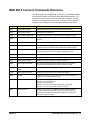
IEEE 488.2 Common Commands Reference ................................................................... 79
Appendix A - Matrix Modules Specifications ...................................................................... 81
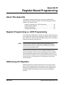
Appendix B - Register-Based Programming ....................................................................... 83
About This Appendix ............................................................................................................ 83
Register Programming vs. SCPI Programming ................................................................ 83
Addressing the Registers..................................................................................................... 83
The Base Address ......................................................................................................... 84
Register Offset ............................................................................................................... 84
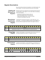
Register Descriptions ........................................................................................................... 86
Reading and Writing to the Registers ......................................................................... 86
Manufacturer Identification Register ........................................................................... 86
Device Type Register .................................................................................................... 86
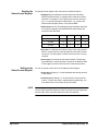
Status/Control Register ................................................................................................. 86
Relay Control Register .................................................................................................. 88
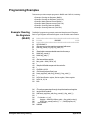
Programming Examples ...................................................................................................... 90
Example: Reading the Registers (BASIC) ................................................................. 90
Example: Reading the Registers (C/HP-UX) ............................................................. 91
Example: Making Measurements (BASIC) ................................................................ 92
Example: Making Measurements (C/HP-UX) ............................................................ 93
Example: Scanning Channels (BASIC) ...................................................................... 95
Example: Scanning Channels (C/HP-UX) .................................................................. 96
Appendix C - Matrix Modules Error Messages ................................................................... 99
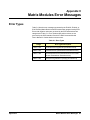
Error Types .................................................................................................................................. 99
Error Messages ................................................................................................................... 100
Appendix D - Relay Life .......................................................................................................... 101
Replacement Strategy ............................................................................................................. 101
Relay Life Factors ............................................................................................................... 101
End-of-Life Determination .................................................................................................. 101
Index ........................................................................................................................................... 103
5
6
AGILENT TECHNOLOGIES WARRANTY STATEMENT
AGILENT PRODUCT: E1465A/E1466A/E1467A Relay Matrix Switch Modules
DURATION OF WARRANTY: 3 years
1. Agilent Technologies warrants Agilent hardware, accessories and supplies against defects in materials and workmanship for the period
specified above. If Agilent receives notice of such defects during the warranty period, Agilent will, at its option, either repair or replace
products which prove to be defective. Replacement products may be either new or like-new.
2. Agilent warrants that Agilent software will not fail to execute its programming instructions, for the period specified above, due to
defects in material and workmanship when properly installed and used. If Agilent receives notice of such defects during the warranty
period, Agilent will replace software media which does not execute its programming instructions due to such defects.
3. Agilent does not warrant that the operation of Agilent products will be interrupted or error free. If Agilent is unable, within a reasonable
time, to repair or replace any product to a condition as warranted, customer will be entitled to a refund of the purchase price upon prompt
return of the product.
4. Agilent products may contain remanufactured parts equivalent to new in performance or may have been subject to incidental use.
5. The warranty period begins on the date of delivery or on the date of installation if installed by Agilent. If customer schedules or delays
Agilent installation more than 30 days after delivery, warranty begins on the 31st day from delivery.
6. Warranty does not apply to defects resulting from (a) improper or inadequate maintenance or calibration, (b) software, interfacing, parts
or supplies not supplied by Agilent, (c) unauthorized modification or misuse, (d) operation outside of the published environmental
specifications for the product, or (e) improper site preparation or maintenance.
7. TO THE EXTENT ALLOWED BY LOCAL LAW, THE ABOVE WARRANTIES ARE EXCLUSIVE AND NO OTHER
WARRANTY OR CONDITION, WHETHER WRITTEN OR ORAL, IS EXPRESSED OR IMPLIED AND AGILENT
SPECIFICALLY DISCLAIMS ANY IMPLIED WARRANTY OR CONDITIONS OF MERCHANTABILITY, SATISFACTORY
QUALITY, AND FITNESS FOR A PARTICULAR PURPOSE.
8. Agilent will be liable for damage to tangible property per incident up to the greater of $300,000 or the actual amount paid for the product
that is the subject of the claim, and for damages for bodily injury or death, to the extent that all such damages are determined by a court
of competent jurisdiction to have been directly caused by a defective Agilent product.
9. TO THE EXTENT ALLOWED BY LOCAL LAW, THE REMEDIES IN THIS WARRANTY STATEMENT ARE CUSTOMER'S
SOLE AND EXLUSIVE REMEDIES. EXCEPT AS INDICATED ABOVE, IN NO EVENT WILL AGILENT OR ITS SUPPLIERS BE
LIABLE FOR LOSS OF DATA OR FOR DIRECT, SPECIAL, INCIDENTAL, CONSEQUENTIAL (INCLUDING LOST PROFIT OR
DATA), OR OTHER DAMAGE, WHETHER BASED IN CONTRACT, TORT, OR OTHERWISE.
FOR CONSUMER TRANSACTIONS IN AUSTRALIA AND NEW ZEALAND: THE WARRANTY TERMS CONTAINED IN THIS
STATEMENT, EXCEPT TO THE EXTENT LAWFULLY PERMITTED, DO NOT EXCLUDE, RESTRICT OR MODIFY AND ARE
IN ADDITION TO THE MANDATORY STATUTORY RIGHTS APPLICABLE TO THE SALE OF THIS PRODUCT TO YOU.
U.S. Government Restricted Rights
The Software and Documentation have been developed entirely at private expense. They are delivered and licensed as "commercial
computer software" as defined in DFARS 252.227- 7013 (Oct 1988), DFARS 252.211-7015 (May 1991) or DFARS 252.227-7014 (Jun
1995), as a "commercial item" as defined in FAR 2.101(a), or as "Restricted computer software" as defined in FAR 52.227-19 (Jun
1987)(or any equivalent agency regulation or contract clause), whichever is applicable. You have only those rights provided for such
Software and Documentation by the applicable FAR or DFARS clause or the Agilent standard software agreement for the product
involved.
E1465A/E1466A/E1467A Relay Matrix Switch Modules User's Manual
Edition 7, Revision 1
Copyright © 1991, 1993, 1995, 1996, 2001 Agilent Technologies, Inc. All rights reserved.
7
Documentation History
All Editions and Updates of this manual and their creation date are listed below. The first Edition of the manual is Edition 1. The Edition
number increments by 1 whenever the manual is revised. Updates, which are issued between Editions, contain replacement pages to
correct or add additional information to the current Edition of the manual. Whenever a new Edition is created, it will contain all of the
Update information for the previous Edition. Each new Edition or Update also includes a revised copy of this documentation history page.
Edition 1 . . . . . . . . . . . . . . . . . . . . . . . . . . . . . . . . . . . . . . . . . . . . . . . July, 1991
Edition 2 . . . . . . . . . . . . . . . . . . . . . . . . . . . . . . . . . . . . . . . . . . . . . . . July, 1993
Edition 3 . . . . . . . . . . . . . . . . . . . . . . . . . . . . . . . . . . . . . . . . . . . . . . . June, 1995
Edition 4 . . . . . . . . . . . . . . . . . . . . . . . . . . . . . . . . . . . . . . . . . . . . January, 1996
Edition 5 . . . . . . . . . . . . . . . . . . . . . . . . . . . . . . . . . . . . . . . . . . . . . . . May, 1996
Edition 6 . . . . . . . . . . . . . . . . . . . . . . . . . . . . . . . . . . . . . . . . . . November, 1996
Edition 7 . . . . . . . . . . . . . . . . . . . . . . . . . . . . . . . . . . . . . . . . . . . . . March, 2001
Edition 7, Revision 1 . . . . . . . . . . . . . . . . . . . . . . . . . . . . . . . . September, 2015
Safety Symbols
Instruction manual symbol affixed to
product. Indicates that the user must refer to
the manual for specific WARNING or
CAUTION information to avoid personal
injury or damage to the product.
Alternating current (AC)
Direct current (DC).
Warning. Risk of electrical shock.
Indicates the field wiring terminal that must
be connected to earth ground before
operating the equipment - protects against
electrical shock in case of fault.
or
Frame or chassis ground terminal-typically
connects to the equipment's metal frame.
Calls attention to a procedure, practice, or
WARNING condition that could cause bodily injury or
death.
Calls attention to a procedure, practice, or
CAUTION condition that could possibly cause damage to
equipment or permanent loss of data.
WARNINGS
The following general safety precautions must be observed during all phases of operation, service, and repair of this product. Failure to
comply with these precautions or with specific warnings elsewhere in this manual violates safety standards of design, manufacture, and
intended use of the product. Agilent Technologies assumes no liability for the customer's failure to comply with these requirements.
Ground the equipment: For Safety Class 1 equipment (equipment having a protective earth terminal), an uninterruptible safety earth
ground must be provided from the mains power source to the product input wiring terminals or supplied power cable.
DO NOT operate the product in an explosive atmosphere or in the presence of flammable gases or fumes.
For continued protection against fire, replace the line fuse(s) only with fuse(s) of the same voltage and current rating and type. DO NOT
use repaired fuses or short-circuited fuse holders.
Keep away from live circuits: Operating personnel must not remove equipment covers or shields. Procedures involving the removal of
covers or shields are for use by service-trained personnel only. Under certain conditions, dangerous voltages may exist even with the
equipment switched off. To avoid dangerous electrical shock, DO NOT perform procedures involving cover or shield removal unless you
are qualified to do so.
DO NOT operate damaged equipment: Whenever it is possible that the safety protection features built into this product have been
impaired, either through physical damage, excessive moisture, or any other reason, REMOVE POWER and do not use the product until
safe operation can be verified by service-trained personnel. If necessary, return the product to Agilent for service and repair to ensure that
safety features are maintained.
DO NOT service or adjust alone: Do not attempt internal service or adjustment unless another person, capable of rendering first aid and
resuscitation, is present.
DO NOT substitute parts or modify equipment: Because of the danger of introducing additional hazards, do not install substitute parts
or perform any unauthorized modification to the product. Return the product to Agilent for service and repair to ensure that safety features
are maintained.
8
DECLARATION OF CONFORMITY
According to ISO/IEC Guide 22 and CEN/CENELEC EN 45014
Manufacturer's Name:
Manufacturer's Address:
Agilent Technologies, Inc.
Basic, Emerging and Systems Technologies Product Generation Unit
815 14th Street S.W.
Loveland, CO 80537 USA
Declares, that the product
Product Name:
Model Number:
Product Options:
Relay Matrix Switch Modules
E1465A/E1466A/E1467A
This declaration includes all options of the above product(s).
Conforms with the following European Directives:
The product herewith complies with the requirements of the Low Voltage Directive 73I23IEEC and the EMC Directive 89I336IEEC
and carries the CE Marking accordingly.
Conforms with the following product standards:
EMC
Standard
Limit
/EC 61326-1:1997 + A1:1998 I EN 61326-1:1997 + A1:1998
Group 1, Class A [1]
4 kV CD, 8 kV AD
3 VIm, 80-1000 MHz
0.5 kV signal lines, 1 kV power lines
0.5 kV line-line, 1 kV line-ground
3 V, 0.15-80 MHz
1 cycle, 100%
C/SPR 11:1997 + A1:1997 I EN 55011-1991
/EC 61000-4-2:1995+A1998 I EN 61000-4-2:1995
/EC 61000-4-3:1995 I EN 61000-4-3:1995
/EC 61000-4-4:1995 I EN 61000-4-4:1995
/EC 61000-4-5:1995 I EN 61000-4-5:1995
/EC 61000-4-6:1996 I EN 61000-4-6:1996
/EC 61000-4-11:1994 I EN 61000-4-11:1994
Canada: /CES-001:1998
AustraliaINew Zealand: ASINZS 2064.1
Safety
/EC 61010-1:1990+A1:1992+A2:1995 I EN 61010-1:1993+A2:1995
Canada: CSA C22.2 No. 1010.1:1992
UL 3111-1
Supplemental Information:
[1] The product was tested in a typical configuration with Agilent Technologies test systems.
September 5, 2000
Date
Name
Quality Manager
Title
For further information, please contact your local Agilent Technologies sales office, agent or distributor.
Authorized EU-representative: Agilent Technologies Deutschland GmbH, Herrenberger Stra� e 130, D 71034 Boblingen, Germany
Revision: A.03
Issue Date: 09/05/00
9
Notes:
10
Chapter 1
Getting Started
Using This Chapter
This chapter gives guidelines to get started using the E1465A, E1466A, and
E1467 Relay Matrix Switch Modules (matrix modules), including:
• Matrix Modules Description ............................................................ 11
• Programming the Matrix Modules ..................................................15
Matrix Modules Description
The E1465A, E1466A, and E1467A Relay Matrix Switch modules are
VXIbus C-Size register-based modules that can operate with a command
module, such as an E1406A. Four 4x16 submatrixes are implemented on
the PC board with 256 latching relays. Terminal modules convert the submatrixes into 4x64 (E1466A), 8x32 (E1467A), or 16x16 (E1465A) matrixes.
Agilent plug-in modules installed in an mainframe or used with a command
module are treated as independent instruments, each having a unique
secondary GPIB address. Each instrument is assigned a dedicated error
queue, input and output buffers, status registers, and if applicable,
dedicated mainframe/command module memory space for readings or data.
An instrument may be composed of a single plug-in module or multiple
plug-in modules.
NOTE The matrix model number is determined by the terminal module connected
to the PC board. /f no terminal module is connected, the relay matrix switch
module defaults to an E1466A. To program the E1465A and E1467A, make
certain the terminal module is connected.
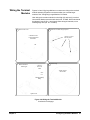
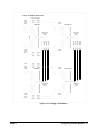
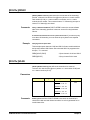
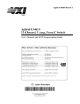
The E1465A Relay Matrix module (Figure 1-1) provides a 16x16 two-wire
crosspoint matrix. This 16x16 matrix is created by connecting the terminal
module. The terminal module connects the columns of the submatrixes of
A, B, C, and D.
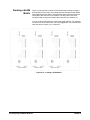
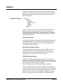
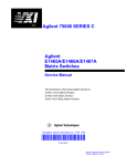
The E1466A Relay Matrix module (Figure 1-2) provides a 4x64 two-wire
crosspoint matrix. This 4x64 matrix is created by connecting the terminal
module. The terminal module connects the rows of submatrixes A, B, C,
and D.
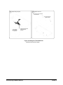
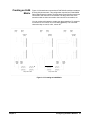
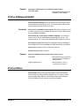
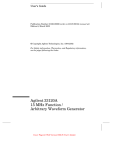
The E1467A Relay Matrix module (Figure 1-3) provides an 8x32 two-wire
crosspoint matrix. This 8x32 matrix is created by connecting the terminal
module. The terminal module connects the rows of submatrixes A and C,
and rows of submatrixes B and D. The columns of submatrixes A and B,
and columns of submatrixes C and D are also connected.
Chapter 1
Getting Started 11
MATRIX MODULE
TERMINAL MODULE
A
B
C
D
Figure 1-1. E1465A 16x16 Relay Matrix Module
12 Getting Started
Chapter 1
MATRIX MODULE
TERMINAL MODULE
A
B
C
D
Figure 1-2. E1466A 4x64 Relay Matrix Module
Chapter 1
Getting Started 13
MATRIX MODULE
TERMINAL MODULE
A
B
C
D
Figure 1-3. E1467A 8x32 Relay Matrix Module
14 Getting Started
Chapter 1
Programming the Matrix Modules
There are several ways you can program the matrix modules. One way is
to write directly to the registers. This method can provide better throughput
speed, but requires more knowledge of the matrix design. See Appendix B
for information on register-based programming.
Another way to program the matrix module is to use a command module and
Standard Commands for Programmable Instruments (SCPI). With SCPI
commands, the command module parses the commands and writes to the
appropriate relay module register. The examples in this manual use the
SCPI programming language. See Appendix B for examples on writing
directly to the registers.
Addressing the
Modules
To address specific channels (relays) within a matrix module, you specify
the SCPI command and matrix module channel list. The following are the
most commonly used SCPI commands:
• CLOSe channel list
• OPEN channel list
• SCAN channel list
Closes the relays specified
Opens the relays specified
Closes the relays specified, one at a time
Channel List
The channel list is a combination of the card number and the channel
numbers. The channel list takes the form of @ssrrcc where ss = matrix
module card number (00-99), rr = row number of the matrix module, and
cc = column number of the matrix module.
Card Number
The card number (ss of the channel list) identifies the switch module
within a switchbox. The card number assigned depends on the switch
configuration used. Leading zeroes can be ignored for the card number.
For a single-module switchbox configuration, the card number is always 01.
For a multiple-module switchbox configuration, multiplexer modules are set
to successive logical addresses. The multiplexer module with the lowest
logical address is always card number 01. The card number with the next
successive logical address is 02, etc.
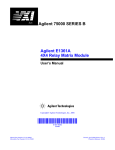
Figure 1-4 illustrates card numbers and logical addresses of a typical
multiple-module switchbox configuration. Chapter 2 shows an example of
addressing a switchbox configuration.
Channel Addresses
The channel address is the rrcc of the channel list. This address determines
which relay will be addressed. Use a comma (,) to form a channe list or
use a colon (:) to form a channel range. You can address single channels
(@ssrrcc), multiple channels (@ssrrcc,ssrrcc,...), sequential channels
(@ssrrcc:ssrrcc), groups of sequential channels (@ssrrcc:ssrrcc,
ssrrcc:ssrrcc), or any combination.
Only valid channels can be accessed in a channel list or channel range.
Also, the channel range must be from a lower channel number to a higher
channel number. For example, CLOS (@10000:20303) is acceptable, but
CLOS (@20303:10000) generates an error. Table 1-1 shows the matrix
modules channel numbers for the three matrix modules.
Chapter 1
Getting Started 15
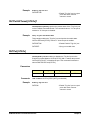
Table 1-1. Matrix Modules Channel Numbers
Matrix Module
Rows (rr)
Columns (cc)
E1465A 16x16 Relay Matrix Switch
00 - 15
00 - 15
E1466A 4x64 Relay Matrix Switch
00 - 03
00 - 63
E1467A 8x32 Relay Matrix Switch
00 - 07
00 - 31
Multiple-Module Switchbox Card Numbers
Card Number 01
Multiplexer Module
1
2
4
8
16
32
64
128
Command
Module
Logical Address = 120
Secondary Address = 15
Card Number 02
1
2
4
8
16
32
64
128
Multiplexer Module
Logical Address = 121
Card Number 03
Multiplexer Module
1
2
4
8
16
32
64
128
Logical Address = 122
Note: Physical placement of the Module in the Logical Address
order is not required, but is recommended.
Figure 1-4. Card Numbers in a Multiple-Module Switchbox
Example: Closing
Relays (BASIC)
This example assumes a PC running BASIC and a GPIB interface. The
program closes row 03, column 12 of an E1465A 16x16 matrix module at
logical address 120 (secondary address = 120/8 = 15) and queries the
result. The result is returned to the controller and displayed (1 = relay closed,
0 = relay open). See Chapter 4 for information on the SCPI commands.
10 OUTPUT 70915; "*RST"
! Resets the module
20 OUTPUT 70915; "CLOS (@10312)" ! Closes row 03, column 12 on
module number 1
30 OUTPUT 70915; "CLOS? (@10312)" ! Query channel 10312
40 ENTER 70915; Value
! Enter result into variable Value
50 PRINT Value
! Print results (should print "1"
to indicate that the channel is
closed)
60 END
! Terminate program
16 Getting Started
Chapter 1
Example: Closing
Relays (Turbo C)
This example assumes a PC with a GPIB Interface card (with command
library) running Borland Turbo C. The program closes row 03, column 12 of
an E1465A 16x16 matrix module at logical address 120 (secondary address
= 120/8 = 15) and queries the result. The result is returned to the controller
and displayed (1 = relay closed, 0 = relay open). See Chapter 4 for
information on the SCPI commands.
#include <stdio.h>
#include <chpib.h>
#define ISC 7L
#define MATRIX 70915L
#define TASK1 "*RST"
#define TASK2 "CLOS (@10312)"
#define TASK3 "CLOS? (@10312)"
/*Include file for GPIB*/
/*Matrix default address*/
/*Reset*/
/*Close row 3, column 12*/
/*Query row 3, column 12*/
main()
{
char into[257];
int length = 256;
/*Output commands to matrix module*/
error_handler (IOTIMEOUT (7L,5.0), "TIMEOUT");
error_handler (IOOUTPUTS (MATRIX, TASK1, 4), "OUTPUT command");
error_handler (IOOUTPUTS (MATRIX, TASK2, 15), "OUTPUT
command");
error_handler (IOOUTPUTS (MATRIX, TASK3, 15), "OUTPUT
command");
/*Enter from matrix*/
error_handler (IOENTERS (MATRIX, into, &length), "ENTER command");
printf("Now let's see if the switch is closed: %s",into);
return;
}
int error_handler (int error, char *routine)
{
char ch;
if (error != NOERR)
{
printf ("\n Error %d %s \n", error, errstr(error));
printf (" in call to GPIB function %s \n\n", routine);
printf ("Press 'Enter' to exit: ");
scanf ("%c", &ch);
exit(0);
}
return 0;
}
Chapter 1
Getting Started 17
Notes:
18 Getting Started
Chapter 1
Chapter 2
Configuring the Matrix Modules
Using This Chapter
This chapter gives guidelines to connect external wiring to the E1465A,
E1466A, and E1467A Relay Matrix Switch modules (matrix module) and
shows how to connect multiple modules together to form larger matrixes.
This chapter includes:
• WARNINGS and CAUTIONS .........................................................19
• Configuring the Switch Module ......................................................20
• Configuring the Terminal Modules .................................................24
• Configuring Larger Matrixes ...........................................................30
WARNINGS and CAUTIONS
WARNING SHOCK HAZARD. Only service-trained personnel who are
aware of the hazards involved should install, remove, or
configure matrix modules. Remove all power sources from the
mainframe and installed modules before installing or removing
a module.
CAUTION MAXIMUM INPUTS. The maximum voltage that can be applied to
any terminal is 200 Vdc/170 Vrms. The maximum current that can
be applied to any row or column is 1 A dc or ac peak. The maximum
power that can be applied to any terminal is 30 W or 62.5 VA
(resistive).
CAUTION STATIC ELECTRICITY. Static electricity is a major cause of
component failure. To prevent damage to the electrical components
in a matrix module, observe anti-static techniques when removing or
installing the module or when working on the module.
Chapter 2
Configuring the Matrix Modules 19
Configuring the Switch Module
This section gives guidelines to configure the E1465A/E1466A/E1467A
switch module, including:
• Switch Module Connectors
• Setting the Logical Address Switch
• Setting the Interrupt Level
• Installing the Switch Module in a Mainframe
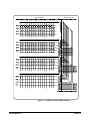
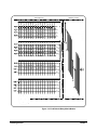
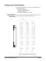
Switch Module
Connectors
Figure 2-1 shows the front panel of the E1465/66/67A switch module and
the connector pin-out that mates to the terminal module.
Bank
Row/Column
L=Low
H=High
Pin
32
Pin
1
Pin
32
Pin
1
Pin
64
GND
GND
A
A
A
A
B
B
NC
NC
A
A
A
A
A
A
A
A
A
A
B
B
B
B
B
B
B
B
B
B
ROW
ROW
ROW
ROW
ROW
ROW
0H
0L
3H
3L
2H
2L
COL
COL
COL
COL
COL
COL
COL
COL
COL
COL
COL
COL
COL
COL
COL
COL
COL
COL
COL
COL
02H
02L
05H
05L
08H
08L
11H
11L
14H
14L
01H
01L
04H
04L
07H
07L
10H
10L
13H
13L
C
C
C
C
C
C
C
C
C
C
C
C
D
D
D
D
D
D
D
D
D
D
NC
NC
C
C
D
D
COL
COL
COL
COL
COL
COL
COL
COL
COL
COL
COL
COL
COL
COL
COL
COL
COL
COL
COL
COL
COL
COL
00H
00L
03H
03L
06H
06L
09H
09L
12H
12L
15H
15L
02H
02L
05H
05L
08H
08L
11H
11L
14H
14L
ROW
ROW
ROW
ROW
2H
2L
1H
1L
GND
CF(10)
A
A
B
B
B
Pin
33
Pin
64
A
A
A
A
A
A
A
A
A
A
A
A
B
B
B
B
B
B
B
B
B
B
C
C
C
C
C
C
C
C
C
C
D
D
D
D
D
D
D
D
D
D
D
D
C
C
C
C
D
D
Pin
33
Pin
96
GND
GND
ROW
ROW
ROW
ROW
ROW
ROW
COL
COL
COL
COL
COL
COL
COL
COL
COL
COL
COL
COL
COL
COL
COL
COL
COL
COL
COL
COL
COL
COL
1H
1L
0H
0L
3H
3L
00H
00L
03H
03L
06H
06L
09H
09L
12H
12L
15H
15L
02H
02L
05H
05L
08H
08L
11H
11L
14H
14L
COL
COL
COL
COL
COL
COL
COL
COL
COL
COL
COL
COL
COL
COL
COL
COL
COL
COL
COL
COL
COL
COL
ROW
ROW
ROW
ROW
ROW
ROW
01H
01L
04H
04L
07H
07L
10H
10L
13H
13L
00H
00L
03H
03L
06H
06L
09H
09L
12H
12L
15H
15L
0H
0L
3H
3L
2H
2L
CF(13)
CF(11)
Pin
65
Pin
96
GND
GND
A
A
B
B
NC
NC
A
A
A
A
A
A
A
A
A
A
B
B
B
B
B
B
B
B
B
B
B
B
ROW
ROW
ROW
ROW
2H
2L
1H
1L
COL
COL
COL
COL
COL
COL
COL
COL
COL
COL
COL
COL
COL
COL
COL
COL
COL
COL
COL
COL
COL
COL
01H
01L
04H
04L
07H
07L
10H
10L
13H
13L
00H
00L
03H
03L
06H
06L
09H
09L
12H
12L
15H
15L
C
COL
COL
COL
COL
COL
COL
COL
COL
COL
COL
COL
COL
COL
COL
COL
COL
COL
COL
COL
COL
02H
02L
05H
05L
08H
08L
11H
11L
14H
14L
01H
01L
04H
04L
07H
07L
10H
10L
13H
13L
ROW
ROW
ROW
ROW
ROW
ROW
1H
1L
0H
0L
3H
3L
C
C
C
C
C
C
C
C
C
D
D
D
D
D
D
D
D
D
D
NC
NC
C
C
D
D
D
D
Pin
65
GND
CF(12)
Figure 2-1. Relay Matrix Switch Module Pin-out
20 Configuring the Matrix Modules
Chapter 2
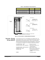
Setting the Logical
Address Switch
The logical address switch (LADDR) factory setting is 120. Valid address
values are from 1 to 255. The matrix module can be configured as a single
instrument or as a switchbox. See Figure 2-2 for switch position information.
NOTE The address switch selected value must be a multiple of 8 if the module is
the first module in a switchbox used with a VX/bus command module and
is being instructed by SCP/ commands.
Logical Address = 120
128
64
Logical Address
Switch Location
32
8+16+32+64=120
16
8
4
2
OPEN
CLOSED
1
CLOSED = Switch Set To 1 (ON)
OPEN = Switch Set To 0 (OFF)
Figure 2-2. Setting the Module Logical Address
Setting the Interrupt
Level
The matrix module generates an interrupt after a channel has been closed.
These interrupts are sent to, and acknowledgements are received from, the
command module (such as an E1406A) via the VXIbus backplane interrupt
lines. For applications where the matrix module is installed in a C-Size
mainframe and is a servant of the command module, the interrupt line
jumper does not have to be moved. See Figure 2-3 to change the interrupt
line.
You can select seven different interrupt line levels. Line X disables the
interrupt and should not be used. The module's factory setting is line 1.
To change the setting, remove the four-pin jumper (part number 1258-0247)
from the old line location and reinstall the jumper in the new line location.
If you are setting the interrupt line to something other than 1, see the
E1406A Command Module User's Manual for additional information. If the
four-pin jumper is not used, the two jumper locations must have the same
interrupt line selected.
Chapter 2
Configuring the Matrix Modules 21
NOTE
When the E1406A Command Module is the resource manager, the
interrupt line jumper must be installed in position 1. However, if you are
using an embedded computer with the E1406A Command Module,
interrupt line 2 should be selected. The Level X interrupt line should not
be used under normal operating conditions.
Using 2-Pin
Jumper
Using 4-Pin
Jumper
Logical Address
IRQ
IRQ
7
6
7
6
5
4
3
2
1
X
5
4
3
2
1
X
Switch Location
Interrupt
Priority
Location
Figure 2-3. Setting the Interrupt Level
22 Configuring the Matrix Modules
Chapter 2
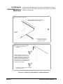
Installing the
Switch Module in a
Mainframe
1
E1465/66/67A Relay Matrix Switch modules may be installed in any slot
(except slot 0) in a C-size VXIbus mainframe. See Figure 2-4 to install the
module in a mainframe.
Set the extraction levers out.
2
Slide the module into any slot (except slot 0)
until the backplane connectors touch.
Extraction
Levers
3
4
Seat the module into the
mainframe by pushing in
the extraction levers.
Tighten the top and bottom screws
to secure the module to the
mainframe.
NOTE: The extraction levers will not
seat the backplane connectors on older
VXIbus mainframes. You must manually
seat the connectors by pushing in the
module until the module's front panel is
flush with the front of the mainframe. The
extraction levers may be used to guide or
remove the switch module.
To remove the module from the mainframe,
reverse the procedure.
Figure 2-4. Installing the Switch Module in a VXIbus Mainframe
Chapter 2
Configuring the Matrix Modules 23
Configuring the Terminal Modules
This section gives guidelines to configure the E1465A/E1466A/E1467A
terminal modules, including:
• Terminal Module Connectors
• Wiring Terminal Modules
• Connecting Terminal Modules to the Switch Module
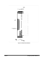
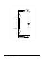
Terminal Module
Connectors
Figure 2-5 shows the E1465A terminal module connectors and associated
row/column designators. Figure 2-6 shows the E1466A terminal module
connectors and associated row/column designators. Figure 2-7 shows
the E1467A terminal module connectors and associated row/column
designators.
Daisy Chain
Row (00-07)
Column
(00-07)
Daisy Chain
Column
(00-07)
Rows
(00-07)
Rows
(08-15)
Daisy Chain
Coumn
(08-15)
Daisy Chain
Row (08-15)
Column
(08-15)
Figure 2-5. E1465A Terminal Module
24 Configuring the Matrix Modules
Chapter 2
Columns
(00-31)
Rows
(00-03)
Daisy Chain Rows
for Expansion
Columns
(32-63)
Figure 2-6. E1466A Terminal Module
Chapter 2
Configuring the Matrix Modules 25
Rows (00-07)
Columns (00-15)
Columns (16-31)
Daisy Chain Rows
for Expansion
Figure 2-7. E1467A Terminal Module
26 Configuring the Matrix Modules
Chapter 2
Wiring the Terminal
Modules
Figures 2-8 and 2-9 give guidelines to connect user wiring to the terminal
module assembly. Expansion connectors allow you to create larger
matrixes. See "Configuring Larger Matrixes" for details.
User wiring to the matrix modules is to the High (H) and Low (L) terminal
connections. Maximum terminal wire size is No. 16 AWG. Wire ends should
be stripped 6 mm (0.25 in.) and tinned. When wiring all channels, use a
smaller gauge wire (No. 20 - 22 AWG).
1
2
Remove clear cover.
Remove and retain wiring exit panel.
A. Release screws.
Remove 1 of the 3
wire exit panels.
B. Press tab forward
and release.
Tab
3
4
Make connections.
Screw type
Route wiring.
Use wire
size 16-26
AWG
Tighten wraps to
secure wires.
5mm
0.2"
VW1 Flammability
Rating
Insert wire into terminal.
Tighten screw.
Figure 2-8. Wiring the Terminal Module
Continued on next page
Chapter 2
Configuring the Matrix Modules 27
5
6
Replace wiring exit panel.
Replace clear cover.
A. Hook in the top cover tabs
onto the fixture.
B. Press down and
tighten screws.
Cut required
holes in panels.
for wire exit
Keep wiring exit panel
hole as small as
possible.
Figure 2-9. Wiring the Terminal Module
Continued from previous page
28 Configuring the Matrix Modules
Chapter 2
Attaching the
Terminal Modules
to the Switch
Module
Figure 2-10 shows how to attach the E1465A, E1466A, or E1467A terminal
modules to the switch module.
1
Extend the extraction levers on the terminal
module.
3
Apply gentle pressure to attach the terminal
module to the Relay Matrix Switch Module.
2
Align the terminal module connectors to the
Relay Marix Switch Module.
4
Push in the extraction levers to lock the
terminal module onto the Relay Matrix Switch
Module.
Extraction Lever
Use small screwdriver
to release the two
extraction levers
Extraction
Levers
E1466A
Module
Extraction Lever
To remove the terminal
module from the Relay Matrix
Switch Module, use a small screwdriver to release the two extraction
levers and push both levers out simultaneously
to free it from the Relay Matrix Switch Module.
Figure 2-10. Attaching the Terminal Modules to the Switch Module
Chapter 2
Configuring the Matrix Modules 29
Configuring Larger Matrixes
This section gives guidelines to create larger matrixes, including:
• Creating Larger Matrixes
• Creating a 32x32 Matrix
• Creating a 4x256 Matrix
• Creating an 8x96 Matrix
• Creating Larger Matrixes with Multiple Mainframes
Creating Larger
Matrixes
You can create larger matrixes with the matrix modules by using the
E1466-80002 Daisy Chain Expansion cable. With larger matrixes, more
crosspoints become available. A C-Size mainframe can have up to 3,072
two-wire crosspoints. You can make a larger matrix by connecting the rows
or columns of one terminal module to the corresponding rows or columns of
the next terminal module. Only the E1465A has a column expansion. You
can also create larger matrixes by connecting multiple mainframes together.
When using multiple modules, the modules should be configured as a
switchbox. That is, the first switch card (module) has a logical address that
is a multiple of 8 and succeeding switch cards have sequential logical
addresses. For example, if you use the matrix default address of 120 for the
first card, the remaining cards in the switchbox would have logical addresses
of 121, 122, 123, etc.
When using multiple modules configured as a switchbox, you must address
the modules as a switchbox. For example, if you want to close row 00,
column 05 on the second card, use CLOSe @20005).
Creating a 32x32
Matrix
Figure 2-11 shows how to connect four E1465A 16x16 modules to create a
32-row by 32-column matrix. This configuration requires 16 E1466-80002
Daisy Chain Expansion cables. The daisy chain rows of modules 1 and 3
are connected to the rows of cards 2 and 4 to increase the number of
columns.
The daisy chain columns of cards 1 and 3 are connected together and the
daisy chain columns of cards 2 and 4 are connected together. For example,
to connect row 16 to column 15 use CLOSe (@30015). This command will
close the relay on card 3, row 00, column 15. The following table shows
which cards support applicable rows and columns.
Cards (Modules)
30 Configuring the Matrix Modules
Rows/Columns
Cards 1 and 2
Rows 00 - 15
Cards 3 and 4
Rows 16 - 31
Cards 1 and 3
Columns 00 - 15
Cards 2 and 4
Columns 16 - 31
Chapter 2
E1465A TERMINAL MODULES
Daisy Chain Cable
Daisy
Chain
Rows
(00-07)
Rows
(00-07)
MODULE 1
MODULE 2
Daisy Chain
Columns
(00-15)
Daisy
Chain
Rows
(08-15)
Daisy
Chain
Rows
(16-23)
Daisy Chain
Columns
(16-31)
Rows
(08-15)
Rows
(16-23)
MODULE 3
MODULE 4
Daisy Chain
Columns
(00-15)
Daisy
Chain
Rows
(24-31)
Daisy Chain
Columns
(16-31)
Rows
(24-31)
Figure 2-11. Creating a 32x32 Matrix
Chapter 2
Configuring the Matrix Modules 31
Creating a 4x256
Matrix
Figure 2-12 shows how to connect four E1466A 4x64 modules to create a
4-row by 256-column matrix. This configuration requires three E1466-80002
Daisy Chain Expansion cables. The daisy chain rows of the first module are
connected to the rows of the next module. The daisy chain rows of the
second module are then connected to the rows of the next module, etc.
Columns
(128-191)
Daisy
Chain
Row
Daisy
Chain
Row
Daisy
Chain
Row
Daisy Chain Cable
Daisy Chain Cable
Daisy Chain Cable
Rows (0-3)
Columns
(64-127)
Rows (0-3)
Columns
(0-63)
Rows (0-3)
Rows (0-3)
You can continue this pattern to create even larger matrixes. For example,
to connect row 03 to column 255, use CLOSe (@40363). This command will
close the relay on card 4, row 3, column 63.
Columns
(192-255)
Daisy
Chain
Row
Figure 2-12. Creating a 4x256 Matrix
32 Configuring the Matrix Modules
Chapter 2
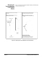
Creating an 8x96
Matrix
Figure 2-13 shows how to connect three E1467A 8x32 modules to create an
8-row by 96-column matrix. This configuration requires four E1466-80002
Daisy Chain Expansion cables. The daisy chain rows of the first module are
connected to the rows of the next module. The daisy chain rows of the
second module are then connected to the rows of the next module, etc.
You can continue this pattern to create even larger matrixes. For example,
to connect row 4 to column 32, use CLOSe (@20400). This command
closes the relay on card 2, row 4, column 00.
Rows
(4-7)
Rows
(0-3)
Columns
(0-31)
Daisy
Chain
Row
Daisy
Chain
Row
Rows
(4-7)
Rows
(0-3)
Rows
(4-7)
Columns
(32-63)
Columns
(64-95)
Daisy
Chain
Row
Daisy Chain Cable
Rows
(0-3)
Daisy
Chain
Row
Daisy Chain Cable
Figure 2-13. Creating an 8x96 Matrix
Chapter 2
Configuring the Matrix Modules 33
Creating Larger
Matrixes with
Multiple Mainframes
Figure 2-14 shows one way to connect C-Size mainframes together using
GPIB. The matrix switch modules in each mainframe are then configured as
switchboxes. The switchbox card numbers are 1, 2, 3, etc. in each
mainframe and each mainframe has a different address.
For example, to address the second module in the second mainframe, use
OUTPUT 70815; "CLOSe (@20001)", where the interface select code is 7,
the command module primary address is 08, and and the matrix module's
secondary address is 15. This address selects card 2, row 00, column 01.
E1406A
Command Module
(Primary Address = 09)
E1466A (Logical Address = 120. Secondary Address = 15)
E1406A
Command Module
(Primary Address = 08)
E1466A (Logical Address = 120. Secondary Address = 15)
E1406A
Command Module
(Primary Address = 07)
E1466A (Logical Address = 120. Secondary Address = 15)
E1466A (Logical Address = 121)
E1466A (Logical Address = 122)
E1466A (Logical Address = 121)
E1466A (Logical Address = 122)
E1466A (Logical Address = 121)
E1466A (Logical Address = 122)
GPIB
Figure 2-14. Creating Larger Matrixes with Multiple Mainframes
34 Configuring the Matrix Modules
Chapter 2
Chapter 3
Using the Matrix Modules
Using This Chapter
This chapter uses typical examples to show ways to use the E1465A,
E1466A, and E1467A Relay Matrix Switch modules (matrix modules).
See Chapter 4 for command information. Chapter contents are:
• Matrix Modules Commands ............................................................35
• Power-on and Reset Conditions ....................................................36
• Matrix Modules Identification ..........................................................36
• Switching Channels .........................................................................38
• Scanning Channels..........................................................................39
• Querying Matrix Modules ................................................................42
• Using the Scan Complete Bit..........................................................42
• Saving and Recalling States.............................................................. 44
• Detecting Error Conditions ..............................................................45
• Synchronizing Matrix Modules .......................................................46
• Understanding Matrix Modules ......................................................47
NOTE
All examples in this chapter use GP/B select code 7, primary address 09,
and secondary address 15 (LADDR = 120) for the matrix modules.
Matrix Modules Commands
Table 3-1 explains some of the SCPI commands used in this chapter.
See Chapter 4 for more information on these commands.
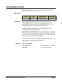
Table 3-1. Matrix Modules Commands Used in Chapter 3
SCPI Command
Command Description
[ROUTe:]CLOSe <channel_list>
Closes the channels in the <channel list>
[ROUTe:]CLOSe? <channel_list>
Queries the state of the channels in the <channel list>
[ROUTe:]OPEN <channel_list>
Opens the channels in the <channel list>
[ROUTe:]OPEN? <channel_list>
Queries the state of the channels in the <channel list>
[ROUTe:]SCAN <channel_list>
Closes the channels in the <channel list>, one at a time
INITiate[:IMMediate]
Starts scan sequence and closes first channel in the <channel list>
TRIGger:SOURce <source>
Selects the trigger source to advance the scan
Chapter 3
Using the Matrix Modules 35
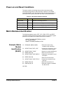
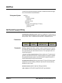
Power-on and Reset Conditions
The matrix modules use latching relays and the relay state remains
unchanged during power-up and power-down. However, if an E1406A
Command Module is used, the firmware opens all relays during power-up
and a when *RST (reset) is executed. See Table 3-2 for default values.
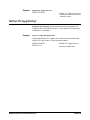
Table 3-2. *RST (Reset) Default Conditions
Parameter
Default
Description
ARM:COUNt
1
Number of scanning cycles is 1
TRIGger:SOURce
IMM
Will advance scanning cycles automatically
INITiate:CONTinuous OFF
OFF
OUTPut[:STATe]
Number of scanning cycles is set by ARM:COUNt
Trigger output from EXT or TTL sources is disabled
Matrix Modules Identification
The following programs use the *RST, *CLS, *IDN?, CTYP?, and CDES?
commands to reset and identify the matrix modules. For example, a typical
printout for the E1465A 16x16 matrix module will be similar to:
HEWLETT-PACKARD,SWITCHBOX,0,A.04.00
16 x 16 Matrix Switch
HEWLETT-PACKARD,E1465A,0,A.04.00
Example: Matrix
Module
Identification
(BASIC)
10
DIM A$[50], B$[50], C$[50]
/ Dimensions three string
variables to fifty characters
20
OUTPUT 70915;"*RST; *CLS"
! Outputs the commands to reset
and clears the status register
30
OUTPUT 70915; "*IDN?"
! Queries for module identification
40
ENTER 70915; A$
/ Enters the results into A$
50
OUTPUT 70915; "SYST:CDES? 1"
! Outputs the command for a card
description
60
ENTER 70915; B$
! Enters the results into B$
70
OUTPUT 70915; "SYST:CTYP? 1"
! Outputs the command for the
card type
80
ENTER 70915; C$
! Enters the results into C$
90
PRINT A$, B$, C$
! Prints the contents of variables
A$, B$, and C$
100 END
36 Using the Matrix Modules
Chapter 3
Example: Matrix
Module
Identification
(TURBO C)
#include <stdio.h>
#include <chpib.h>
/*Include file for GPIB*/
#define ISC 7L
/*Matrix default address*/
#define MATRIX 70915L
#define TASK1 "*RST;*CLS;*IDN?" /*Reset, clear, and query id*/
/*Command for card description*/
#define TASK2 "SYST:CDES? 1"
#define TASK3 "SYST:CTYP? 1"
/*Command for card type*/
main( )
{
char into1[51], into2[51], into3[51];
int length = 50;
/*Output and enter commands to matrix module*/
error_handler (IOTIMEOUT (7L,5.0), "TIMEOUT");
error_handler (IOOUTPUTS (MATRIX, TASK1, 15), "OUTPUT command");
error_handler (IOENTERS (MATRIX, into1, &length), "ENTER command");
error_handler (IOOUTPUTS (MATRIX, TASK2, 12), "OUTPUT command");
error_handler (IOENTERS (MATRIX, into2, &length), "ENTER command");
error_handler (IOOUTPUTS (MATRIX, TASK3, 12), "OUTPUT command");
error_handler (IOENTERS (MATRIX, into3, &length), "ENTER command");
printf("IDENTIFICATION: %s",into1);
printf("CARD DESCRIPTION: %s",into2);
printf("CARD TYPE: %s",into3);
return;
}
int error_handler (int error, char *routine)
{
char ch;
if (error != NOERR)
{
printf ("\n Error %d %s \n", error, errstr(error));
printf (" in call to GPIB function %s \n\n", routine);
printf ("Press 'Enter' to exit: ");
scanf ("%c", &ch);
exit(0);
}
return 0;
}
Chapter 3
Using the Matrix Modules 37
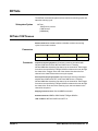
Switching Channels
Use CLOSe <channel list> to close one or more matrix module channels
and OPEN <channel list> to open the channel(s). channel_list has the
form @ssrrcc where ss = card number (01-99), rr is the row number, and
cc = column number. See Table 3-3 for row and column definitions for the
modules.
To OPEN or CLOSe multiple channels, place a comma (,) between the
channel numbers. For example, to close channels 10103 and 10201,
execute CLOS (@10103,10201). To OPEN or CLOSe a continuous range
of channels, place a colon (:) between the first and last channel numbers.
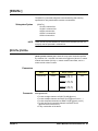
Table 3-3. Matrix Modules Channel Numbers
Matrix Module
Example:
Opening/Closing
Channels (BASIC)
Rows (rr)
Columns (cc)
E1465A 16 x 16 Relay Matrix
00 - 15
00 - 15
E1466A 4 x 64 Relay Matrix
00 - 03
00 - 63
E1467A 8 x 32 Relay Matrix
00 - 07
00 - 31
This BASIC program shows one way to close and open row 2, column 14
on an E1466A matrix module (card #1). In the program, implied commands
are those that appear in square brackets ([ ]) in the command syntax. The
brackets are not part of the command and are not sent to the instrument.
For example, in the following program, ROUTe can be eliminated and
just the CLOSe or OPEN command can be used.
10 DISP "TEST E1465A Matrix"
20 OUTPUT 70915; "ROUT:CLOS (@10214)"
30 OUTPUT 70915; "ROUT:OPEN (@10214)"
40 END
Example: Channel
Sequencing
(BASIC)
This example BASIC program sequences through each channel on an
E1466A 4x64 matrix module.
10 OUTPUT 70915;"*RST"
! Reset the module
20 FOR Row = 0 TO 3
! Loop to step through all
rows in the matrix
30
! Loop to step through all
columns in the matrix
FOR Col = 0 TO 63
40
Addr=10000+100*row+Col
50
OUTPUT 70915; "CLOS (@ ";Addr;")"
! Calculates channel to close
! Closes the channel
60
NEXT Col
70 NEXT Row
! Sequences through each
column in the matrix
! Sequences through each row
in the matrix
80 END
38 Using the Matrix Modules
Chapter 3
Scanning Channels
Scanning matrix module channels consists of closing a sequence of
channels one channel at a time. Single scan, multiple scans, or continuous
scanning modes are available. TRIGger:SOURce specifies the source to
advance the scan. OUTPut can be used to enable the E1406A Command
Module Trig Out port or TTL Trigger bus lines (0-7).
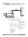
Example: Scanning
Channels Using
TTL Triggers
(BASIC)
This example uses the E1406A Command Module TTL Trigger Bus Lines
to synchronize matrix module channel closures to an E1412A system
multimeter. For measurement synchronization, the E1406A TTL Trigger
Bus Line 0 is used by the matrix module to trigger the multimeter to perform
a measurement. The E1406A TTL Trigger Bus Line 1 is used by the
multimeter to advance the matrix module channel scan.
Note that these trigger bus lines are not actual hardware connections.
Triggering is accomplished by the E1406A firmware. Row 00 (High and Low)
of an E1465A 16x 6 matrix module is connected to the voltmeter's High and
Low. The columns are then scanned, switching in different DUTs (devices
under test).
Figure 3-1 shows how to connect the matrix module to the multimeter
module. The connections shown with dotted lines are not actual hardware
connections, but indicate how the firmware operates to accomplish the
triggering.
E1406A
Command Module
E1466A
Matrix Module
E1412A
Multimeter Module
E1466A
Terminal Module
TTLTrg0
Trigger
TTLTrg1
VM
Complete
TTLTrg1
TTLTrg0
HI
Row 00H
Row 00L
LO
Figure 3-1. Example: Scanning Using TTL Triggers
Chapter 3
Using the Matrix Modules 39
This BASIC example program sets up the multimeter (GPIB address 70903)
to scan making two-wire resistance measurements. The E1465A matrix
module is set to scan row 00, columns 00 to 15.
10 ALLOCATE REAL Rdgs(1:16)
20 OUTPUT 70915; "*RST;*CLS"
! Reset and clear the matrix
module
30 OUTPUT 70903; "*RST;*CLS"
! Reset and clear the multimeter
40 OUTPUT 70903; "ABORT;:TRIG:SOUR TTLTRG0"
! Multimeter triggers on TTL
Trigger line 0
50 OUTPUT 70903; "OUTP:TTLTRG1:STAT ON"
! Multimeter pulses TTL Trigger
line 1 on measurement
complete
60 OUTPUT 70903; "CONF:RES AUTO,DEF"
! Set multimeter function to
Resistance
70 OUTPUT 70903; "TRIG:DEL 0;COUN 16;:CAL:ZERO:AUTO ON"
! Set multimeter Range, NPLC
functions
80 OUTPUT 70903; "*OPC?"
90 ENTER 70903; Check
! Check to see if multimeter ready
100 OUTPUT 70903; "INIT"
! When multimeter is ready,
initialize trigger
110 OUTPUT 70915; "TRIG:SOUR TTLTRG1"
! Set matrix module to be
triggered by TTL Trigger line 1
120 OUTPUT 70915; "OUTPUT:TTLT0:STATE ON"
! Matrix module pulses TTL
Trigger line 0 on channel closed
130 OUTPUT 70915; "SCAN (@10000:10015
! Scan list is Row 0, Columns
0 to 15
140 OUTPUT 70915; "INIT"
! /nitiate scan
150 OUTPUT 70903; "FETCH?"
160 ENTER 70903; Rdgs(*)
! Enter readings
170 PRINT Rdgs(*)
! Print readings
180 END
40 Using the Matrix Modules
Chapter 3
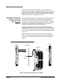
Example: Scanning
Using Trig In/Out
Ports (BASIC)
This example uses the E1406A Command Module Trig In and Trig Out ports
to synchronize the matrix module channel closures to an external 3457A
voltmeter at address 722. Figure 3-2 shows how to connect the voltmeter to
the command module and to the matrix module.
E1406A
Command
Module
+5V
0V
+5V
0V
Trig
In
Trig
Out
Voltmeter
Complete
External
Trigger
3457A Multimeter (Rear View)
Row 00L
E1466A
Matrix Module
Row 00H
E1466A
Terminal Module
Figure 3-2. Example: Scanning Using Trig In and Trig Out Ports
10 OUTPUT 722; "TRIG EXT; DCV;MEM FIFO"
! Set voltmeter for external
trigger, DCV measurements,
memory first in, first out storage
20 OUTPUT 70915; "*RST;*CLS"
! Reset and clear the matrix
module
30 OUTPUT 70915; "OUTP ON"
! Enable the E1406A Trig Out port
40 OUTPUT 70915; "TRIG:SOUR:EXT" ! Set trigger source to external
triggering
50 OUTPUT 70915; "SCAN (@10000:10015)"
! Set matrix measurement mode
and define channel list
60 OUTPUT 70915; "INIT"
! /nitiate scan
70 WAIT 2
! Wait 2 seconds
80 FOR Channels = 1 to 16
90
ENTER 722;Results
100
PRINT Results
110 NEXT Channels
120 END
Chapter 3
Using the Matrix Modules 41
Querying Matrix Modules
All query commands end with a "?". These commands are used to determine
a specific state of the matrix module. Data are sent to the output buffer
where it can be retrieved into a computer. CLOSe? <channel list> and
OPEN? <channel list> return the current state of the specified channel.
These commands return "1" if the operation is true and return "0" if the
operation is false. A maximum of 128 channels can be queried at one time.
Therefore, to query more than 128 channels, you must enter the query data
in two separate commands. See Chapter 4 for more information on query
commands.
Example: Querying
Channel Closure
(BASIC)
This BASIC example program closes a range of channels on an E1467A
8x32 matrix module and queries the results.
10 DIM Chan1$[128], Chan2$[128]
! Dimensions two string variables
to 128 characters each
20 OUTPUT 70915;"CLOS (@10000:10731)"
! Closes rows 00 through 07 and
columns 00 through 31
30 OUTPUT 70915; "CLOS? (@10000:10331)"
! Queries rows 00 through 03
and columns 00 through 31
40 ENTER 70915; Chan1$
! Enters the results of the first
128 channel closures
50 OUTPUT 70914; "CLOS? (@10400:10731)"
! Queries rows 04 through 07
and columns 00 through 31
60 ENTER 70915; Chan2$
! Enters the results of the second
128 channel closures
70 PRINT "Channels closed";Chan1$, Chan2$
! Prints all channels closed
(should print 1s)
80 END
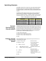
Using the Scan Complete Bit
The Scan Complete Bit (bit 8) in the OPERation Status Register (in the
command module) can be used to determine when a scanning cycle
completes. (No other bits in this register apply to the switchbox.) Bit 8
has a decimal value of 256 and can be read directly using STAT:OPER?.
See STATus:OPERation[:EVENt]? in Chapter 4.
When enabled by STAT:OPER:ENAB 256, the Scan Complete Bit is
reported as Bit 7 of the Status Byte Register. You can use the GPIB Serial
Poll or the IEEE 488.2 Common command *STB? to read the Status
Register.
42 Using the Matrix Modules
Chapter 3
When Bit 7 of the Status Byte Register is enabled by *SRE 128 to assert a
GPIB Service Request (SRQ), the computer can be interrupted when the
Scan Complete Bit is set, after the scanning cycle completes. This allows
the controller to do other operations while the scanning cycle is in progress.
Example: Using the
Scan Complete Bit
(BASIC)
This example monitors bit 7 in the Status Byte Register to determine when
the scanning cycle is complete. The computer interfaces with an E1406A
Command Module over GPIB. The GPIB select code is 7, primary address
is 09, and secondary address is 15.
10 OUTPUT 70915;"*RST; *CLS"
! Reset and clear the matrix
module
20 OUTPUT 70915; "STATUS:OPER:ENABLE 256"
! Enable Scan Complete Bit
30 OUTPUT 70915; "TRIG:SOUR IMM" ! Set matrix module for
continuous triggering
40 OUTPUT 70915; "SCAN (@10000:10015)"
! Select channels to scan
50 OUTPUT 70915; "*OPC?"
! Wait for operation complete
60 ENTER 70915; A$
70 PRINT "*OPC? = ";A$
80 OUTPUT 70915; "STAT:OPER:ENAB?"! Query OPERation Status
register contents
90 ENTER 70915; A$
100 PRINT "STAT:OPER:ENAB? = ";A$
110 OUTPUT 70915; "*STB?"
! Query Status Byte register
contents
120 ENTER 70915; A$
130 PRINT "Switch Status = ";A$
140 OUTPUT 70915; "INIT"
! Start scan cycle
150 I = 0
! /nitialize counter value
160 WHILE (I=0)
! Stay in loop until value is
returned from SPOLL (70915)
170
I = SPOLL(70915)
180
PRINT "Waiting for scan to complete: SPOLL = ";I
190 END WHILE
200 I = SPOLL(70915)
210 PRINT "Scan complete: SPOLL = ";I
220 END
Chapter 3
Using the Matrix Modules 43
Saving and Recalling States
*SAV <numeric state> stores the current state of the matrix modules
channels. Up to 10 states can be stored by specifying <numeric state> as
an integer 0 through 9. The following states are stored: Channel relay states
(open or closed), ARM:COUNt, TRIGger:SOURce, OUTPut[:STATe], and
INITiate:CONTinuous.
*RCL <numeric state> recalls the specified previously stored state. If the
specified <numeric state> does not exist, the matrix module configures to
its power-on/reset states (see Table 3-2).
Example: Saving
and Recalling
States (BASIC)
This program shows one way to save and recall matrix modules states.
10 DIM A$[30]
! Dimensions string variable
A$ to 30 characters
20 OUTPUT 70915; "CLOS (@10000:10015)
! Closes channels on a matrix
module
30 OUTPUT 70915; "*SAV 5"
! Saves state as numeric state 5
40 OUTPUT 70915; "*RST; *CLS"
! Resets and clears the matrix
module
50 OUTPUT 70915; "CLOS? (@10000:10020)"
! Query to see which channels
are closed
60 ENTER 70915;A$
70 PRINT "Channels Closed:";A$
80 OUTPUT 70915; "*RCL 5"
! Recall numeric state 5
90 OUTPUT 70915; "CLOS? (@10000:10200)"
! Check if recalled channels are
closed
100 ENTER 70915; A$
110 PRINT "Channels Closed:";A$
! Prints 1s for first 16 channels
closed and 0s for remaining 5
channels
120 END
44 Using the Matrix Modules
Chapter 3
Detecting Error Conditions
SYSTem:ERRor? requests a value from instrument's error register. This
register contains an integer in the range [-32768 to 32767]. The response
takes the form <err number>,<err message>, where <err number> is the
value of the instrument's error and <err message> is a short description of
the error.
If no error occurs, the switchbox responds with 0,"No error". If there has
been more than one error, the instrument will respond with the first error in
its error queue. Subsequent queries continue to read the error queue until it
is empty. The maximum <err message> string length is 255 characters.
Example: Detecting
Error Conditions
(BASIC)
This BASIC example program attempts an illegal channel closure for the
E1466A 4x64 matrix module and polls for the error message.
10 DIM Err_num$[256]
! Dimensions Err num$ for 256
characters
20 OUTPUT 70915; "CLOS (@10500)"
! Try to close an illegal channel
30 OUTPUT 70915; "SYST:ERR?"
! Check for a system error
40 ENTER 70915; Err_num$
! Enter the errors into Err num$
50 PRINT Err_num$
! Prints error +2001, "/nvalid
channel number"
60 END
Example: Detecting
Error Conditions
(TURBO C)
This Turbo C example program attempts an illegal channel closure for the
E1466A 4x64 matrix module and polls for the error message.
#include <stdio.h>
#include <chpib.h>
/*Include file for GPIB*/
#define ISC 7L
/*Matrix module default address*/
#define MATRIX 70915L
#define TASK1 "CLOSE (@10500)" /*Command for illegal switch closure*/
#define TASK2 "SYST:ERR?"
/*Command for system error*/
main()
{
char into[257];
int length = 256;
/*Output commands to matrix module*/
error_handler (IOTIMEOUT (7L,5.0), "TIMEOUT");
error_handler (IOOUTPUTS (MATRIX, TASK1, 15), "OUTPUT
command");
error_handler (IOOUTPUTS (MATRIX, TASK2, 9), "OUTPUT command");
Chapter 3
Using the Matrix Modules 45
/*Enter from matrix module*/
error_handler (IOENTERS (MATRIX, into, &length), "ENTER command");
printf("Print the errors: %s",into);
return;
}
int error_handler (int error, char *routine)
{
char ch;
if (error != NOERR)
{
printf ("\n Error %d %s \n", error, errstr(error));
printf (" in call to GPIB function %s \n\n", routine);
printf ("Press 'Enter' to exit: ");
scanf ("%c", &ch);
exit(0);
}
return 0;
}
Synchronizing Matrix Modules
This section gives guidelines to synchronize matrix modules with
measurement instruments.
Example:
Synchronizing a
Matrix Module
(BASIC)
This BASIC example program shows how to synchronize matrix modules
with measurement instruments. In this example, a matrix module switches a
signal to a multimeter. The program verifies that the channel is closed before
the multimeter begins its measurement.
10 OUTPUT 70915; "*RST"
! Reset the module
20 OUTPUT 70915; "CLOS (@10012)" ! Close a channel
30 OUTPUT 70915; "*OPC?"
! Wait for operation complete
40 ENTER 70915; Opc_value
50 OUTPUT 70915; "CLOS? (@10012)" !Test that the channel is closed
60 ENTER 70915;A
70 IF A=1 THEN
80
OUTPUT 70903;"MEAS:VOLT:DC?" ! When channel is closed,
measure the voltage
90
ENTER 70903; Meas_value
100
PRINT Meas_value
! Print the measured value
110 ELSE
120
PRINT "Channel did not close"
130 END IF
140 END
46 Using the Matrix Modules
Chapter 3
Understanding Matrix Modules
This section provides internal configuration details about the E1465,
E1466A, and E1467A matrix modules, including advantages of latching
relays and module operation.
Advantages of
Latching Relays
There are several advantages to using the E1465A/E1466A/E1467A
latching relays, as follows. The main disadvantage of latching relays is
that the relay state is unchanged at power-on, power-off, or following a reset.
Therefore, the device's firmware must ensure that all relays are open
following these conditions.
• With 256 relays on the dense matrix relay module, latching relays
prevent excessive current being drawn from the power supply if
the user closes too many relays accidentally. Energy is saved
since power is not continually applied to keep a latching relay
closed.
• By not continually applying power, the relay coil does not heat up.
This is important because the two metal contacts inside the relay,
in effect, form a thermocouple. Thus, temperature differences on
the relay contacts cause thermal EMF (electromotive force) to be
generated.
• The life of a latching relay is usually longer than that of a
nonlatching relay because of the power that must be continually
applied to close a nonlatching relay.
• In conventional switch module designs, the module interrupts the
central processing unit (CPU) each time a relay is opened or
closed. For the E1465A/E1466A/E1467A matrix relay modules,
the CPU is interrupted one time after all relays in the specified
channel list have been opened or closed. Thus, system
throughput speed is increased.
Matrix Module
Operations
The following paragraphs describe matrix module operations (see Figure
3-3).
• A command is sent to the matrix module and is stored in FIFO
memory.
• Once the data is in memory, the VME Timing PAL (programmable
array logic) asserts DTACK*. This signals the CPU on the matrix
module's commander that it is now free to service other tasks.
• The VME Timing PAL signals the FIFO Interface PAL to execute
the command. During execution, the Data Bus FIFO EMPTY*
flag signals the FIFO Interface PAL to read the Data Bus and
Address Bus FIFO and generate 7 msec pulses to activate the
relays. Only one 7 msec pulse is required per relay bank (up to
16 relays).
Chapter 3
Using the Matrix Modules 47
• The FIFO Interface PAL reads the Data Bus and Address Bus
FIFO until the EMPTY* flag signals the FIFO Interface PAL the
FIFO memory is empty.
• When the FIFO is empty, the FIFO Interface PAL signals the VME
Timing PAL which asserts IRQ*. This interrupts the command
module CPU after the last relay has been activated.
• Because the matrix module asserts IRQ* after the last relay is
activated, the CPU is not continually interrupted. Thus, system
throughput is enhanced.
Power
Add
Bus
Card
Add
Detector
Sysreset
& Control
Bus
Card
Reset &
Logic
Address
Bus
FIFO
Empty *
Add
Decoder
Driver
& One Shot
FIFO-Write
DTACK
IRQ*
Card Reset*
FIFO-Read
VME
Timing
PAL
Data
Bus
FIFO
Data
Bus
FIFO
Interface
PAL
Data
Bus
Buffer
Device
ID
Register
Data
Bus
Driver
Latching
Relay
Power
Ground
Status &
Control
Register
Figure 3-3. Matrix Modules Block Diagram
48 Using the Matrix Modules
Chapter 3
Chapter 4
Matrix Modules Command Reference
Using This Chapter
This chapter describes Standard Commands for Programmable Instruments
(SCPI) and summarizes IEEE 488.2 Common (*) commands applicable to
the E1465A, E1466A, and E1467A Relay Matrix Switch modules. This
chapter contains the following sections:
• Command Types ..............................................................................49
• SCPI Command Reference ............................................................51
• SCPI Commands Quick Reference ...............................................78
• IEEE 488.2 Common Commands Reference ..............................79
Command Types
Commands are separated into two types: IEEE 488.2 Common commands
and SCPI commands.
Common Command
Format
The IEEE 488.2 standard defines the Common commands that perform
functions like reset, self-test, status byte query, etc. Common commands
are four or five characters in length, always begin with the asterisk character
(*), and may include one or more parameters. The command keyword is
separated from the first parameter by a space character. Some examples
of Common commands are shown below:
*RST
SCPI Command
Format
*ESR 32
*STB?
The SCPI commands perform functions like closing switches, opening
switches, scanning channels, querying instrument states or retrieving data.
A subsystem command structure is a hierarchical structure that usually
consists of a top level (or root) command, one or more lower-level
commands, and their parameters. The following example shows part of a
typical subsystem:
[ROUTe:]
CLOSe<channel list>
SCAN <channel list>
[ROUTe:] is the root command, CLOSe and SCAN are second-level
commands with parameters. There must be a space between the
second-level command (such as CLOSe) and the parameter
(<channel list>).
Chapter 4
Matrix Modules Command Reference 49
Command Separator
A colon (:) always separates one command from the next lower-level
command as shown below:
[ROUTe:]SCAN
Colons separate the root command from the second-level command
([ROUTe:]SCAN).
Abbreviated Commands
The command syntax shows most commands as a mixture of upper- and
lowercase letters. The uppercase letters indicate the abbreviated spelling for
the command. For shorter program lines, send the abbreviated form. For
better program readability, you may send the entire command. The
instrument will accept either the abbreviated form or the entire command.
For example, if the command syntax shows TRIGger, then TRIG and
TRIGGER are both acceptable forms. Other forms of TRIGger, such as
TRIGG or TRIGGE will generate an error. You may use uppercase or
lowercase letters. Therefore, TRIGGER, trigger, and TrigGeR are all
acceptable.
Implied Commands
Implied commands are those that appear in square brackets ([ ]) in the
command syntax. (The brackets are not part of the command and are not
sent to the instrument.) Suppose you send a second-level command but do
not send the preceding implied command. In this case, the instrument
assumes you intend to use the implied command and it responds as if you
had sent it. Examine the portion of the [ROUTe:] subsystem shown below:
[ROUTe:]
CLOSe<channel list>
The root command [ROUTe:] is an implied command (indicated by square
brackets ([ ])). To make a query about a channel's present status, you can
send either of the following command statements:
ROUT:CLOSe? <channel list> or CLOSe? <channel list>
Linking Commands
Linking IEEE 488.2 Common Commands with SCPI Commands. Use a
semicolon (;) between the commands. For example, *RST;OUTP ON or
TRIG:SOUR HOLD;:*RST.
Linking Multiple SCPI Commands. Use both a semicolon (;) and a colon (:)
between the commands, such as ARM:COUN 1;:TRIG SOUR EXT.
50 Matrix Modules Command Reference
Chapter 4
Parameters
The following table contains explanations and examples of parameter types
you might see later in this chapter.
Type
Explanations and Examples
Boolean
Represents a single binary condition that is either true or
false (ON, OFF, 1.0). Any non-zero value is considered
true.
Discrete
Selects from a finite number of values. These parameters
use mnemonics to represent each valid setting. An
example is the TRIGger:SOURce <source> command
where <source> can be BUS, EXTernal, HOLD,
IMMediate, or TTLTrgn.
Numeric
Commonly used decimal representations of numbers
including optional signs, decimal points, and scientific
notation. Examples are 123, 123E2, -123, -1.23E2, .123,
1.23E-2, 1.23000E-01. Special cases include MINimum,
MAXimum, DEFault and INFinity.
Optional
Parameters shown within square brackets ([ ]) are optional
parameters. (The brackets are not part of the command
and are not sent to the instrument.) If you do not specify a
value for an optional parameter, the instrument chooses a
default value.
For example, consider the ARM:COUNt? [<MIN I MAX>]
command. If you send the command without specifying a
parameter, the present ARM:COUNt value is returned. If
you send the MIN parameter, the command returns the
minimum count available. If you send the MAX parameter,
the command returns the maximum count available. Be
sure to place a space between the command and the
parameter.
SCPI Command Reference
This section describes the Standard Commands for Programmable
Instruments (SCPI) commands for the E1465A, E1466A, and E1467A Relay
Matrix Switch Modules. Commands are listed alphabetically by subsystem
and within each subsystem.
Chapter 4
Matrix Modules Command Reference 51
ABORt
The ABORt command stops a scan in progress when the scan is enabled
via the interface and the trigger source is TRIGger:SOURce BUS or
TRIGger:SOURce HOLD.
Subsystem Syntax
Comments
ABORt
ABORt Actions: The ABORt command terminates the scan and invalidates
the current channel list.
Stopping Scan Enabled Via Interface: When a scan is enabled via an
interface, an interface CLEAR command can be used to stop the scan.
When the scan is enabled via the interface and TRIG:SOUR BUS or HOLD
is set, you can use ABORt to stop the scan.
Restarting a Scan: Use INIT to restart the scan.
Related Commands: ARM, INITiate:CONTinuous,[ROUTe:]SCAN, TRIGger
Example
Stopping a Scan with ABORt
This example stops a (continuous) scan in progress.
TRIG:SOUR BUS
! Trigger command will be via
backplane (bus) interface
(*TRG generates trigger)
INIT:CONT ON
SCAN(@10000:10003)
! Set continuous scanning
! Scan channels 00 to 03
INIT
! Start scan, close channel 00
.
.
ABOR
52 Matrix Modules Command Reference
! Abort scan in progress
Chapter 4
ARM
The ARM subsystem selects the number of scanning cycles (1 to 32,767)
for each INITiate command.
Subsystem Syntax
ARM
:COUNt <number> MIN I MAX
:COUNt? [<MIN I MAX>]
ARM:COUNt
ARM:COUNt <number> MIN I MAX allows scanning to occur a multiple of
times (1 to 32,767) with one INITiate command when INITiate:CONTinuous
OFF I 0 is set. MIN sets 1 cycle and MAX sets 32,767 cycles.
Parameters
Comments
Name
Type
Range of Values
Default Value
<number>
numeric
1 - 32,767 I MIN I MAX
1
Number of Scans: Use only numeric values between 1 and 32767, MIN, or
MAX for the number of scanning cycles.
Related Commands: ABORt, INITiate[:IMMediate]
*RST Condition: ARM:COUNt 1
Example
Setting Ten Scanning Cycles
This example sets a relay matrix for 10 scans of channels 10000 through
10003. When the scan sequence completes, channels 10000 through
10003 are closed.
Chapter 4
ARM:COUN 10
! Set 10 scans per /N/T command
SCAN(@10000:10003)
! Scan channels 10000-10003
INIT
! Start scan, close channel 10000
Matrix Modules Command Reference 53
ARM:COUNt?
ARM:COUNt? [<MIN I MAX>] returns the current number of scanning cycles
set by ARM:COUNt. The current number of scan cycles is returned when
MIN or MAX is not specified. With MIN or MAX as a parameter, MIN returns
"1" and MAX returns "32,767".
Parameters
Comments
Example
Name
Type
Range of Values
Default Value
MIN I MAX
numeric
MIN = 1, MAX = 32,767
current cycle
Related Commands: INITiate[:IMMediate]
Querying Number of Scans
This example sets a switchbox for 10 scanning cycles and queries the
number of scan cycles set. The ARM:COUN? command returns 10.
ARM:COUN 10
! Set 10 scans per /N/T
ARM:COUN?
! Query number of scans
54 Matrix Modules Command Reference
Chapter 4
DISPlay
The DISPlay subsystem monitors the channel state of the selected module
in a switchbox. This subsystem operates with an E1406A Command Module
when a display terminal is connected.
Subsystem Syntax
DISPlay
:MONitor
:CARD <number> I AUTO
[:STATe] <mode>
DISPlay:MONitor:CARD
DISPlay:MONitor:CARD <number> I AUTO selects the module in a switchbox
to be monitored.
Parameters
Comments
Name
Type
Range of Values
Default Value
<number> I AUTO
numeric
1 - 99
AUTO
Selecting a Specific Module to be Monitored: Use DISPlay:MONitor:CARD
to send the card number for the switchbox to be monitored.
Selecting the Present Module to be Monitored: Use DISPlay:MONitor:CARD
AUTO to select the last module addressed by a switching command (for
example, [ROUTe:]CLOSe).
*RST Conditions: DISPlay:MONitor:CARD AUTO
Example
Select Module #2 in a Switchbox for Monitoring
DISP:MON:CARD 2
Chapter 4
! Selects module #2 in a switchbox
Matrix Modules Command Reference 55
DISPlay:MONitor[:STATe]
DISPlay:MONitor[:STATe] <mode> turns the monitor mode ON or OFF.
Parameters
Comments
Name
Type
Range of Values
Default Value
<mode>
boolean
ON I OFF I 1 I 0
OFF I 0
Monitoring Switchbox Channels: DISPlay:MONitor:STATe ON or
DISPlay:MONitor:STATe 1 turns the monitor mode ON to show the
channel state of the selected module. DISPlay:MONitor:STATe OFF or
DISPlay:MONitor:STATe 0 turns the channel monitor OFF.
Selecting the Module to be Monitored: Use DISPlay:MONitor:CARD
<number> AUTO to select the module.
Monitor Mode with a Matrix Module: When monitoring mode is turned ON, a
hexadecimal number representing the channels closed will be displayed at
the bottom of the display terminal. For example, for an E1466A with row 0,
columns 0-3 closed, will look like the following:
R0: 0000 0000 0000 000F R1: 0000 0000 0000 0000 R2: 0000 0000 ... etc.
*RST Condition: DISPlay:MONitor[:STATe]OFF I 0
Example
Enabling Monitor Mode
DISP:MON:CARD 2
! Select module #2 in a switchbox
DISP:MON 1
! Turn monitor mode ON
56 Matrix Modules Command Reference
Chapter 4
INITiate
The INITiate command subsystem selects continuous scanning cycles and
starts the scanning cycle.
Subsystem Syntax
INITiate
:CONTinuous <mode>
:CONTinuous?
[:IMMediate]
INITiate:CONTinuous
INITiate:CONTinuous <mode> enables or disables continuous scanning
cycles for the matrix modules.
Parameters
Comments
Name
Type
Range of Values
Default Value
<mode>
boolean
ON I OFF I 1 I 0
OFF I 0
Continuous Scanning Operation: Continuous scanning is enabled with
INITiate:CONTinuous ON or INITiate:CONTinuous 1. Sending
INITiate:IMMediate closes the first channel in the channel list. Each trigger
from the source specified by TRIGger:SOURce advances the scan through
the channel list. A trigger at the end of the channel list closes the first
channel in the channel list and the scan cycle repeats.
Noncontinuous Scanning Operation: Noncontinuous scanning is enabled
with INITiate:CONTinuous OFF or INITiate:CONTinuous 0. Sending
INITiate:IMMediate closes the first channel in the channel list. Each trigger
from the source specified by TRIGger:SOURce advances the scan through
the channel list. At the end of the scanning cycle, the last channel in the
channel list is opened.
Stopping Continuous Scan: See the ABORt command.
Related Commands: ABORt, ARM:COUNt, TRIGger:SOURce
*RST Condition: INITiate:CONTinuous OFF I 0
Chapter 4
Matrix Modules Command Reference 57
Example
Enabling Continuous Scanning
This example enables continuous scanning of channels 10000 through
10003 of a single-module switchbox. Since TRIGger:SOURce IMMediate
(default) is set, use an interface clear command (such as CLEAR) to stop
the scan.
INIT:CONT ON
! Enable continuous scanning
SCAN(@10000:10003)
! Define channel list
INIT
! Start scan cycle, close channel
10000
INITiate:CONTinuous?
INITiate:CONTinuous? queries the scanning state. With continuous scanning
enabled, the command returns "1" (ON). With continuous scanning
disabled, the command returns "0" (OFF).
Example
Querying Continuous Scanning State
This example enables continuous scanning of a matrix module and queries
the state. Since continuous scanning is enabled, INIT:CONT? returns "1".
INIT:CONT ON
! Enable continuous scanning
INIT:CONT?
! Query continuous scanning state
INITiate[:IMMediate]
INITiate[:IMMediate] starts the scanning process and closes the first channel
in the channel list. Successive triggers from the source specified by
TRIGger:SOURce advance the scan through the channel list.
Comments
Starting the Scanning Cycle: INITiate:IMMediate starts scanning by closing
the first channel in the channel list. Each trigger received advances the scan
to the next channel in the channel list. An invalid channel list definition
causes an error (see [ROUTe:]SCAN).
Stopping Scanning Cycles: See the ABORt command.
Example
Enabling a Single Scan
This example enables a single scan of channels 10000 through 10003 of a
matrix module. The trigger source to advance the scan is immediate
(internal) triggering set with TRIGger:SOURce IMMediate (default).
SCAN(@10000:10003)
! Scan channels 10000 - 10003
INIT
! Begin scan, close channel 10000
(use immediate triggering)
58 Matrix Modules Command Reference
Chapter 4
OUTPut
The OUTPut command subsystem enables or disables the different trigger
lines of the E1406A Command Module.
Subsystem Syntax
OUTPut
:EXTernal
[:STATe] <mode>
[:STATe]?
[:STATe] <mode>
[:STATe]?
:TTLTrgn (:TTLTrg0 through :TTLTrg7)
[:STATe] <mode>
[:STATe]?
OUTPut:EXTernal[:STATe]
OUTPut:EXTernal[:STATe] <mode> enables or disables the "Trig Out" port on
the E1406A Command Module to output a trigger when a channel is closed
during a scan. ON I 1 enables the port and OFF I 0 disables the port.
Parameters
Comments
Name
Type
Range of Values
Default Value
<mode>
boolean
ON I OFF I 1 I 0
OFF I 0
Enabling "Trig Out" Port: When enabled, a pulse is output from the "Trig Out"
port after each scanned switchbox channel is closed. If disabled, a pulse is
not output from the port after channel closures. The output pulse is a +5V
negative-going pulse.
"Trig Out" Port Shared by Switchboxes: When enabled, the "Trig Out" port is
pulsed by any switchbox each time a scanned channel is closed. To disable
the output for a specific module, send OUTPut:EXTernal[:STATe] OFF or
OUTPut:EXTernal[:STATe] 0 for that module.
One Output Selected at a Time: Only one output (TTLTrg or EXTernal) can be
enabled at one time. Enabling a different output source will automatically
disable the active output.
Related Commands: [ROUTe:]SCAN, TRIGger:SOURce
*RST Condition: OUTPut:EXTernal[:STATe] OFF (port disabled)
Chapter 4
Matrix Modules Command Reference 59
Example
Enabling "Trig Out" Port
OUTP:EXT ON
! Enable "Trig Out" port to output
pulse after each scanned
channel is closed
OUTPut:EXTernal[:STATe]?
OUTPut:EXTernal[:STATe]? queries the present state of the "Trig Out" port
on the E1406A Command Module. The command returns "1" if the port is
enabled or "0" if the port is disabled.
Example
Query "Trig Out" Port Enable State
This example enables the "Trig Out" port and queries the enable state.
OUTPut:EXTernal[:STATe]? returns "1" since the port is enabled.
OUTP:EXT ON
! Enable E1406A "Trig Out" port
OUTP:EXT?
! Query port enable state
OUTPut[:STATe]
OUTPut[:STATe] <mode> enables or disables the "Trig Out" port on the
E1406A Command Module. OUTPut[:STATe] ON I 1 enables the port and
OUTPut[:STATe] OFF I 0 disables the port. This command functions the
same as OUTPut:EXTernal[:STATe].
Parameters
Comments
Example
Name
Type
Range of Values
Default Value
<mode>
boolean
ON I OFF I 1 I 0
OFF I 0
*RST Condition: OUTPut[:STATe] OFF (port disabled)
Enabling "Trig Out" Port
OUTP ON
60 Matrix Modules Command Reference
! Enable "Trig Out" port to output
pulse after each scanned
channel is closed
Chapter 4
OUTPut[:STATe]?
OUTPut[:STATe]? queries the present state of the E1406A Command
Module "Trig Out" port. The command returns "1" if the port is enabled
or "0" if the port is disabled. This command functions the same as
OUTPut:EXTernal[:STATe]?.
Example
Query "Trig Out" Port Enable State
This example enables the E1406A Command Module "Trig Out" port and
queries the enable state. OUTPut[:STATe]? returns "1" since the port is
enabled.
OUTP ON
! Enable "Trig Out" port
OUTP?
! Query port enable state
OUTPut:TTLTrgn[:STATe]
OUTPut:TTLTrgn[:STATe] <mode> selects and enables which TTL Trigger
bus line (0 to 7) will output a trigger when a channel is closed during a scan.
This is also used to disable a selected TTL Trigger bus line. "n" specifies the
TTL Trigger bus line (0 to 7) and <mode> enables (ON or 1) or disables
(OFF or 0) the specified TTL Trigger bus line.
Parameters
Comments
Name
Type
Range of Values
Default Value
n
numeric
0 to 7
N/A
<mode>
boolean
ON I OFF I 1 I 0
OFF I 0
Enabling TTL Trigger Bus: When enabled, a pulse is output from the selected
TTL Trigger bus line (0 to 7) after each channel in the switchbox is closed
during a scan. If disabled, a pulse is not output. The output is a
negative-going pulse.
One Output Selected at a Time: Only one output (TTLTrg or EXTernal) can be
enabled at one time. Enabling a different output source will automatically
disable the active output. For example, if TTLTrg1 is the active output and
TTLTrg4 is enabled, TTLTrg1 will become disabled and TTLTrg4 will
become the active output.
Related Commands: [ROUTe:]SCAN, TRIGger:SOURce,
OUTPut:TTLTrgn[:STATe]?
*RST Condition: OUTPut:TTLTrgn[:STATe] OFF (disabled)
Chapter 4
Matrix Modules Command Reference 61
Example
Enabling TTL Trigger Bus Line 7
OUTP:TTLT7:STAT 1
! Enable TTL Trigger bus line 7 to
output pulse after each scanned
channel is closed
OUTPut:TTLTrgn[:STATe]?
OUTPut:TTLTrgn[:STATe]? queries the present state of the specified TTL
Trigger bus line. The command returns "1" if the specified TTLTrg bus line
is enabled or "0" if disabled.
Example
Query TTL Trigger Bus Enable State
This example enables TTL Trigger bus line 7 and queries the enable state.
OUTPut:TTLTrgn? returns "1" since the port is enabled.
OUTP:TTLT7:STAT 1
! Enable TTL Trigger bus line 7
OUTP:TTLT 7?
! Query bus enable state
62 Matrix Modules Command Reference
Chapter 4
[ROUTe:]
The [ROUTe:] command subsystem controls switching and scanning
operations for relay matrix switch modules in a switchbox.
Subsystem Syntax
NOTE
[ROUTe:]
CLOSe <channel list>
CLOSe? <channel list>
OPEN <channel list>
OPEN? <channel list>
SCAN <channel list>
There must be a space between the second level command (CLOSe, for
example) and the parameter <channel list>.
[ROUTe:]CLOSe
[ROUTe:]CLOSe <channel_list> closes the relay matrix channels specified
by <channel list>. <channel list> has the form (@ssrrcc) where ss = matrix
module card number (01-99), rr = matrix module row number, and cc =
matrix module column number.
Parameters
Name
Type
<channel list>
numeric
Range of Values
E1465A: rr: 00 - 15
cc: 00 - 15
Default Value
N/A
E1466A: rr: 00 - 03
cc: 00 - 63
E1467A: rr: 00 - 07
cc: 00 - 31
Comments
Closing Channels:
• To close a single channel use ROUT:CLOS (@ssrrcc)
• To close multiple channels use ROUT:CLOS (@ssrrcc,ssrrcc,...)
• To close sequential channels use ROUT:CLOS (@ssrrcc:ssrrcc)
• To close groups of sequential channels use ROUT:CLOS
(@ssrrcc:ssrrcc,ssrrcc:ssrrcc)
• or any combination of the above
Chapter 4
Matrix Modules Command Reference 63
NOTE
Closure order for multiple channels with a single command is not
guaranteed. Channel numbers can be in the <channel list> in any
random order.
Related Commands: [ROUTe:]OPEN, [ROUTe:]CLOSe?
*RST Condition: All channels open.
Example
Closing Matrix Modules Channels
This example closes channels 10100 and 20013 of a two-module switchbox
(card numbers 01 and 02).
CLOS(@10100,20013)
! Closes row 1, column 00 of card
#1 and row 00, column 13 of card
#2.
[ROUTe:]CLOSe?
[ROUTe:]CLOSe? <channel_list> returns the current state of the channel(s)
queried. <channel list> has the form (@ssrrcc) where cc = card number
(01-99) and nn = channel number (00-31). The command returns "1" if
channel(s) are closed or returns "0" if channel(s) are open.
Comments
Query is Software Readback: ROUTe:CLOSe? returns the current software
state of the channel(s) specified. It does not account for relay hardware
failures.
A maximum of 128 channels can be queried at one time. If you want to query
more than 128 channels, you must enter the query data in two separate
commands.
Example
Querying Channel Closure
This example closes channels 100 and 213 of a two-module switchbox and
queries channel closure. Since the channels are programmed to be closed
"1,1" is returned as a string.
CLOS(@100,213)
!Close channels 100 and 213
CLOS?(@100,213)
!Query channels 100 and 213
state
64 Matrix Modules Command Reference
Chapter 4
[ROUTe:]OPEN
[ROUTe:]OPEN <channel_list> opens the relay matrix channels specified by
<channel list>. <channel list> has the form (@ssrrcc) where ss = matrix
module card number (01-99), rr = matrix module row number, and cc =
matrix module column number.
Parameters
Name
Type
<channel list>
numeric
Range of Values
E1465A: rr: 00 - 15
cc: 00 - 15
Default Value
N/A
E1466A: rr: 00 - 03
cc: 00 - 63
E1467A: rr: 00 - 07
cc: 00 - 31
Comments
Opening Channels:
• To open a single channel use ROUT:OPEN (@ssrrcc)
• To open multiple channels use ROUT:OPEN (@ssrrcc,ssrrcc,...)
• To open sequential channels use ROUT:OPEN (@ssrrcc:ssrrcc)
• To open groups of sequential channels use ROUT:OPEN
(@ssrrcc:ssrrcc,ssrrcc:ssrrcc)
• or any combination of the above
Opening Order: Opening order for multiple channels with a single command
is not guaranteed.
Related Commands: [ROUTe:]CLOSe, [ROUTe:]OPEN?
*RST Condition: All channels open.
Example
Opening Matrix Modules Channels
This example opens channels 10100 and 20013 of a two-module switchbox
(card numbers 01 and 02).
OPEN(@10100,20013)
Chapter 4
! Opens channels 10100 and
20013
Matrix Modules Command Reference 65
[ROUTe:]OPEN?
[ROUTe:]OPEN? <channel_list> returns the current state of the channel(s)
queried. <channel list> has the form (@ssrrcc) where ss = matrix module
card number (01-99), rr = matrix module row number, and cc = matrix
module column number. The command returns "1" if channel(s) are open or
returns "0" if channel(s) are closed.
Comments
Query is Software Readback: ROUTe:OPEN? returns the current software
state of the channel(s) specified. It does not account for relay hardware
failures.
A maximum of 128 channels can be queried at one time: If you want to query
more than 128 channels, you must enter the query data in two separate
commands.
Example
Querying Channel Open State
This example opens channels 10100 and 20013 of a two-module switchbox
and queries channel 20013 state. Since channel 20013 is programmed to
be open, "1" is returned.
OPEN(@10100,20013)
! Open channels 10100 and 20013
OPEN?(@20013)
! Query channel 20013 state
[ROUTe:]SCAN
[ROUTe:]SCAN <channel_list> defines the channels to be scanned.
<channel list> has the form (@ssrrcc) where cc = card number 01-99) and
nn = channel number (00-31).
Parameters
Name
Type
<channel list>
numeric
Range of Values
E1465A: rr: 00 - 15
cc: 00 - 15
Default Value
N/A
E1466A: rr: 00 - 03
cc: 00 - 63
E1467A: rr: 00 - 07
cc: 00 - 31
Comments
Defining Scan List: When ROUTe:SCAN is executed, the channel list is
checked for valid card and channel numbers. An error is generated for an
invalid channel list.
66 Matrix Modules Command Reference
Chapter 4
Scanning Channels:
• To scan a single channel use ROUT:SCAN (@ssrrcc)
• To scan multiple channels use ROUT:SCAN (@ssrrcc,ssrrcc,...)
• To scan sequential channels use ROUT:SCAN (@ssrrcc:ssrrcc)
• To scan groups of sequential channels use ROUT:SCAN
(@ssrrcc:ssrrcc,ssrrcc:ssrrcc)
• or any combination of the above
NOTE
Channel numbers can be in the <channel list> in any random order.
Scanning Operation: When a valid channel list is defined,
INITiate[:IMMediate] begins the scan and closes the first channel in the
<channel list>. Successive triggers from the source specified by
TRIGger:SOURce advance the scan through the <channel list>. At the
end of the scan, the last trigger opens the last channel.
Stopping Scan: See ABORt
Related Commands: TRIGger, TRIGger:SOURce
*RST Condition: All channels open.
Example
Scanning Using External Device
See "Scanning Channels" in Chapter 3 for examples of scanning programs
using external instruments.
Chapter 4
Matrix Modules Command Reference 67
STATus
The STATus subsystem reports the bit values of the OPERation Status
Register. It also allows you to unmask the bits you want reported from the
Standard Event Status Register and to read the summary bits from the
Status Byte Register.
Subsystem Syntax
STATus
:OPERation
:CONDition?
:ENABle <unmask>
:ENABle?
[:EVENt?]
:PRESet
As shown in Figure 3-1, the STATus subsystem for the E1463A Form C
Switch includes the Status Byte Register, the Standard Event Status
Register, OPERation Status Register, and Output Queue. The Standard
Event Status Register (*ESE?) and the Status Byte Register (*STB?) are
under IEEE 488.2 control.
Status Byte Register
In the Status Byte register, the Operation Status bit (OPR), Request Service
bit (RQS), Standard Event bit (ESB), Message Available bit (MAV) and
Questionable Data bit (QUE) (bits 7, 6, 5, 4 and 3 respectively) can be
queried with the *STB? command.
Standard Event Status Register
In the Standard Event Status Register, you can use *ESE? to query the
"unmask" value (the bits to be logically ORed into the Summary bit).
The registers are queried using decimal-weighted bit values. Decimal
equivalents for bits 0 through 15 are shown in Figure 3-1.
OPERation Status Register
Using STATus:OPERation:ENABle 256 allows only bit 8 to generate a
Summary bit from the OPERation Status Register, since the decimal value
for bit 8 is 256. The decimal values can also used in the inverse manner to
determine the bits set from the value returned by
STATus:OPERation:EVENt? or STATus:OPERation:CONDition?.
The Form C switch driver uses only bit 8 of OPERation Status Register.
This bit is called the Scan Complete bit and is set whenever a scan operation
completes. Since completion of a scan operation is an event in time, bit 8
will never appear set when STATus:OPERation:CONDition? is queried.
However, you can find bit 8 set by using STATus:OPERation:EVENt?.
68 Matrix Modules Command Reference
Chapter 4
NOTE:
Output Queue
QUE = Questionable Data
MAV = Message Available
ESB = Standard Event
RQS = Request Service
OPR = Operation Status
C = Condition Register
EV = Event Register
EN = Enable Register
SRQ = Interface Bus
Service Request
Standard Event Status Register
*ESR?
*ESE <unmask>
*ESE?
Power On
User Request
Command Error
Automatically Set at
Power On Conditions
Execution Error
Device Dependent Error
Query Error
Request Control
Operation Complete
Automatically Set by
Parser
Set by *OPC
Related Commands
are *OPC? and *WAI
0
1
2
3
4
5
6
7
E
Status Byte Register
*STB?
SPOLL
<1>
<2>
<4>
<8>
<16>
<32>
<64>
<128>
*SRE <unmask>
*SRE?
"OR"
+
Summary
Bit
EN
MAV
ESB
RQS
OPR
0
1
2
3
4
5
6
7
Status
Byte
<1>
<2>
<4>
<8>
<16>
<32>
"OR"
+
System
Controller
<128>
Interface Bus
SRQ Line
EN
SRQ
Summary Bit
SRQ
Other
Instrument
SRQ
Other
Instrument
OPERation Status Register
STATus:OPERation:CONDition?
STATus:OPERation:EVENt?
STATus:OPERation:ENABle
STATus:OPERation:ENABle?
STATus:PRESet
Scan Complete
0
1
2
3
4
5
6
7
8
9
10
11
12
13
14
15
C
<1>
<2>
<4>
<8>
<16>
<32>
<64>
<128>
<256>
<512>
<1024>
<2048>
<4096>
<8192>
<16384>
<32768>
EV
EN
Summary
Bit
unmask examples:
Register
bit
unmask
decimal
weight
7
<128>
"OR"
+
"OR"
Operation Complete
+
ESB
*ESE 61 unmasks standard event register bits 0,
2, 3, 4 and 5 (*ESE 128 only unmasks bit 7).
*SRE 128 unmasks the OPR bit (operation) in
the status byte register. This is effective
only if the STAT:OPER:ENAB 256 command
is executed.
STAT:QUES:ENAB 256 unmasks the "Scan Complete"
bit.
Figure 4-1. E1465A/E1466A/E1467A Status System Register Diagram
Chapter 4
Matrix Modules Command Reference 69
STATus:OPERation:CONDition?
STATus:OPERation:CONDition? returns the state of the Condition Register
in the OPERation Status Register. The state represents conditions that are
part of the instrument's operation. The switch module driver does not set bit
8 in the OPERation Status Register (see STATus:OPERation[:EVENt]?).
STATus:OPERation:ENABle
STATus:OPERation:ENABle <unmask> sets an enable mask to allow events
recorded in the Event Register of the OPERation Status Register to send a
Summary bit to the Status Byte Register (bit 7). For matrix modules, when
bit 8 in the OPERation Status Register is set to 1 and bit 8 is enabled by
STATus:OPERation:ENABle, bit 7 in the Status Byte Register is set to 1.
Parameters
Comments
Name
Type
Range of Values
Default Value
<unmask>
numeric
0 through 65,535
N/A
Setting Bit 7 of the Status Byte Register: STATus:OPERation:ENABle 256
sets bit 7 (OPR) of the Status Byte Register to 1 after bit 8 (Scan Complete)
of the OPERation Status Register is set to 1.
Related Commands: [ROUTe:]SCAN
Example
Enabling OPERation Status Register Bit 8
STAT:OPER:ENAB 256
! Enable bit 8 of the OPERation
Status Register to be reported to
bit 7 (OPR) in the Status Byte
Register
STATus:OPERation:ENABle?
STATus:OPERation:ENABle? returns the bit value of the Enable Register
within the OPERation Status Register.
Comments
Output Format: STATus:OPERation:ENABle? returns a decimal-weighted
value from 0 to 65,535 indicating the bits set to true.
Maximum Value Returned: The value returned is the value set by
STATus:OPERation:ENABle <unmask>. However, the maximum
decimal-weighted value used in this module is 256 (bit 8 in the Condition
Register within the OPERation Status Register is set to true).
70 Matrix Modules Command Reference
Chapter 4
Example
Querying the Enable Register in the OPERation Status Register
STAT:OPER:ENAB?
! Query the Enable Register in the
OPERation Status Register
STATus:OPERation[:EVENt]?
STATus:OPERation[:EVENt]? returns which bits in the Event Register within
the OPERation Status Register are set. The Event Register indicates that
a time-related instrument event has occurred.
Comments
Setting Bit 8 of the OPERation Status Register: Bit 8 (Scan Complete) is set
to 1 after a scanning cycle completes. Bit 8 returns to 0 (zero) after sending
STATus:OPERation[:EVENt]?.
Returned Data after sending STATus:OPERation[:EVENt]?: The command
returns "+256" if bit 8 of the OPERation Status Register is set to 1. The
command returns "+0" if bit 8 of the OPERation Status Register is set to 0.
Event Register Cleared: Reading the Event Register within the OPERation
Status Register with STATus:OPERation:EVENt? clears the Event Register.
Aborting a Scan: Aborting a scan will leave bit 8 set to 0.
Related Commands: [ROUTe:]SCAN
Example
Reading the OPERation Status Register After a Scanning Cycle
STAT:OPER?
! Return the bit values of the Event
Register within the OPERation
Status Register
read the register value
+ 256 shows bit 8 is set to 1.
+0 shows bit 8 is set to 0.
STATus:PRESet
STATus:PRESet affects only the Enable Register within the OPERation
Status Register by setting all Enable Register bits to 0. It does not affect
either the Status Byte Register or the Standard Event Status Register.
STATus:PRESet does not clear any of the Event Registers.
Chapter 4
Matrix Modules Command Reference 71
SYSTem
The SYSTem subsystem returns the error numbers and error messages in
the error queue of a switchbox. It can also return the types and descriptions
of modules (cards) in a switchbox.
Subsystem Syntax
SYSTem
:CDEScription? <number>
:CPON <number> I ALL
:CTYPe? <number>
:ERRor?
SYSTem:CDEScription?
SYSTem:CDEScription? <number> returns the description of a selected
module (card) in a switchbox.
Parameters
Comments
Name
Type
Range of Values
Default Value
<number>
numeric
1 through 99
N/A
E1465A Module Description: SYSTem:CDEScription? returns:
"16 x 16 Matrix Switch"
E1466A Module Description: SYSTem:CDEScription? returns:
"4 x 64 Matrix Switch"
E1467A Module Description: SYSTem:CDEScription? returns:
"8 x 32 Matrix Switch"
Example
Reading the Description of a Module
SYST:CDES? 1
72 Matrix Modules Command Reference
! Return description of module
card #1
Chapter 4
SYSTem:CPON
SYSTem:CPON <number> I ALL sets the selected module (card) in a
switchbox to its power-on state.
Parameters
Comments
Name
Type
Range of Values
Default Value
<number>
numeric
1 through 99 I ALL
N/A
Matrix Module Power-on State: The power-on state is all channels (relays)
open. *RST opens all channels of all modules in a switchbox, while
SYSTem:CPON <number> opens the channels in only the module (card)
specified in the command.
Example
Setting Module to Power-on State
SYST:CPON 1
! Set card #1 to power-on state
SYSTem:CTYPe?
SYSTem:CTYPe? <number> returns the module (card) type of a selected
module in a switchbox.
Parameters
Comments
Name
Type
Range of Values
Default Value
<number>
numeric
1 through 99
N/A
E1465A Matrix Module Model Number: SYSTem:CTYPe? <number> returns:
HEWLETT-PACKARD,E1465A,0,A.04.00
where the 0 after E1465A is the module serial number (always 0) and
A.04.00 is an example of the module revision code number.
E1466A Matrix Module Model Number: SYSTem:CTYPe? <number> returns:
HEWLETT-PACKARD,E1466A,0,A.04.00
where the 0 after E1466A is the module serial number (always 0) and
A.04.00 is an example of the module revision code number.
Chapter 4
Matrix Modules Command Reference 73
E1467A Matrix Module Model Number: SYSTem:CTYPe? <number> returns:
HEWLETT-PACKARD,E1467A,0,A.04.00
where the 0 after E1467A is the module serial number (always 0) and
A.4.1 is an example of the module revision code number.
Example
Reading the Model Number of a Module
SYST:CTYP? 1
! Returns the model number
SYSTem:ERRor?
SYSTem:ERRor? returns the error numbers and corresponding error
messages in the error queue of a matrix module. See Appendix C for a
listing of matrix module error numbers and messages.
Comments
Error Numbers/Messages in the Error Queue: Each error generated by a
matrix module stores an error number and corresponding error message
in the error queue. The error message can be up to 255 characters long.
Clearing the Error Queue: An error number/message is removed from the
queue each time SYSTem:ERRor? is sent. The errors are cleared first-in,
first-out. When the queue is empty, each following SYSTem:ERRor?
command returns +0, "No error". To clear all error numbers/messages in
the queue, execute *CLS.
Maximum Error Numbers/Messages in the Error Queue: The queue holds a
maximum of 30 error numbers/messages for each switchbox. If the queue
overflows, the last error number/message in the queue is replaced by -350,
"Too many errors". The least recent error numbers/messages remain in the
queue and the most recent errors are discarded.
Example
Reading the Error Queue
SYST:ERR?
74 Matrix Modules Command Reference
! Query the error queue
Chapter 4
TRIGger
The TRIGger command subsystem controls the triggering operation of
matrix modules in a switchbox.
Subsystem Syntax
TRIGger
[:IMMediate]
:SOURce <source>
:SOURce?
TRIGger[:IMMediate]
TRIGger[:IMMediate] causes a trigger event to occur when the defined trigger
source is TRIGger:SOURce BUS or TRIGger:SOURce HOLD.
Comments
Executing TRIGger[:IMMediate]: Before TRIGger[:IMMediate] will execute,
a channel list must be defined with [ROUTe:]SCAN <channel list> and an
INITiate[:IMMediate] must be executed
BUS or HOLD Source Remains: If selected, TRIGger:SOURce BUS or
TRIGger:SOURce HOLD remains in effect after triggering a switchbox with
TRIGger[:IMMediate].
Related Commands: INITiate, [ROUTe:]SCAN
Example
Advancing Scan Using TRIGger
This example scans a single-module switchbox from channel 10000 through
10003. Since TRIGger:SOURce HOLD is set, the scan is advanced one
channel each time TRIGger is executed.
Chapter 4
TRIG:SOUR HOLD
! Set trigger source to HOLD
SCAN(@10000:10003)
! Define channel list
INIT
! Begin scan, close channel 10000
loop statement
! Start count loop
TRIG
! Advance scan to next channel
increment loop
! /ncrement loop count
Matrix Modules Command Reference 75
TRIGger:SOURce
TRIGger:SOURce <source> specifies the trigger source to advance the
<channel list> during scanning.
Parameters
Parameter Name
Comments
Parameter Type
Parameter Description
BUS
discrete
*TRG or GET command
EXTernal
discrete
"Trig In" port
HOLD
discrete
Hold Triggering
IMMediate
discrete
Immediate Triggering
TTLTrgn
numeric
TTL Trigger Bus Line 0 - 7
Enabling the Trigger Source: TRIGger:SOURce only selects the trigger
source. INITiate[:IMMediate] enables the trigger source.
Using the TRIGger Command: You can use TRIGger[:IMMediate] to advance
the scan when TRIGger:SOURce BUS or TRIGger:SOURce HOLD is
selected.
Using External Trigger Inputs: With TRIGger:SOURce EXTernal selected,
only one switchbox at a time can use the external trigger input at the E1406A
"Trig In" port. The trigger input is assigned to the first switchbox requesting
the external trigger source (with a TRIGger:SOURce EXTernal command).
Assigning External Trigger: A switchbox assigned with TRIGger:SOURce
EXTernal remains assigned to that source until the switchbox trigger source
is changed to BUS, HOLD, or IMMediate. When the source is changed, the
external trigger source is available to the next switchbox requesting it (with
a TRIGger:SOURce EXTernal command). If a switchbox requests an
external trigger input already assigned to another switchbox, an error is
generated.
Using Bus Triggers: To trigger the switchbox with bus triggers when
TRIGger:SOURce BUS selected, use the IEEE 488.2 common command
*TRG or the GPIB Group Execute Trigger (GET) command.
"Trig Out" Port Shared by Switchboxes: When enabled, the E1406A
Command Module "Trig Out" port is pulsed by any switchbox each time a
scanned channel is closed. To disable the output for a specific module
send OUTPut:EXTernal[:STATe] OFF or OUTPut:EXTernal[:STATe] 0 for
that module.
One Output Selected at a Time: Only one output (TTLTrg or EXTernal) can be
enabled at one time. Enabling a different output source will automatically
disable the active output.
76 Matrix Modules Command Reference
Chapter 4
Related Commands: ABORt, [ROUTe:]SCAN, OUTPut
*RST Condition: TRIGger:SOURce IMMediate
Example
Scanning Using External Triggers
This example uses external triggering (TRIGger:SOURce EXTernal) to scan
channels 0000 through 0003 of a single-module switchbox. The trigger
source to advance the scan is the input to the "Trig In" port on the E1406A
Command Module. When INIT is executed, the scan is started and channel
0000 is closed. Then, each trigger received at the "Trig In" port advances the
scan to the next channel.
Example
TRIG:SOUR EXT
! Select external triggering
SCAN(@10000:10003)
! Scan channels 0000 - 0003
INIT
! Begin scan, close channel 0000
trigger externally
! Advance scan to next channel
Scanning Using Bus Triggers
This example uses bus triggering (TRIG:SOUR BUS) to scan channels 0000
through 0003 of a single-module switchbox. The trigger source to advance
the scan is the *TRG command (as set with TRIGger:SOURce BUS). When
INIT is executed, the scan is started and channel 0000 is closed. Then, each
*TRG command advances the scan to the next channel.
TRIG:SOUR BUS
! Select interface (bus) triggering
SCAN(@10000:10003)
! Scan channels 0000 - 0003
INIT
! Begin scan, close channel 0000
loop statement
! Loop to scan all channels
*TRG
! Advance scan using bus
triggering
increment loop
! /ncrement loop count
TRIGger:SOURce?
TRIGger:SOURce? returns the current trigger source for the switchbox.
The command returns BUS, EXT, HOLD, IMM, or TTLT for sources BUS,
EXTernal, HOLD, IMMediate, or TTLTrgn, respectively.
Example
Querying the Trigger Source
This example sets external triggering and queries the trigger source.
Since external triggering is set, TRIG:SOUR? returns "EXT".
Chapter 4
TRIG:SOUR EXT
! Set external trigger source
TRIG:SOUR?
! Query trigger source
Matrix Modules Command Reference 77
SCPI Commands Quick Reference
The following table summarizes the SCPI Commands for the E1465A,
E1466A, and E1467A Relay Matrix Switch Modules.
Command
Description
ABORt
ABORt
Aborts a scan in progress
ARM
:COUNt <number> MIN I MAX
:COUNt? [MINIMAX]
Multiple scans per INIT command
Queries number of scans
DISPlay
:MONitor:CARD <number> I AUTO
:MONitor[:STATe] <mode>
Selects module to be monitored
Turns monitor mode on or off
INITiate
:CONTinuous <mode>
:CONTinuous?
[:IMMediate]
Enables/disables continuous scanning
Queries continuous scan state
Starts a scanning cycle
OUTPut
[:EXTernal][:STATe] <mode>
[:EXTernal][:STATe]?
[:STATe] <mode>
[:STATe]?
:TTLTrgn[:STATe] <mode>
:TTLTrgn[:STATe]?
Enables/disables the Trig Out port on the E1406
Queries port enable state
Enables/disables the Trig Out port on the E1406
Queries port enable state
Enables/disables TTL trigger bus line pulse
Queries TTL trigger bus line state
[ROUTe:]
CLOSe <channel _list>
CLOSe? <channel _list>
OPEN <channel_list>
OPEN? <channel _list>
SCAN <channel_list>
Closes channel(s)
Queries channel(s) closed
Opens channel(s)
Queries channel(s) opened
Defines channels for scanning
STATus
:OPERation:CONDition?
:OPERation:ENABle <unmask>
:OPERation:ENABle?
:OPERation[:EVENt]?
:PRESet
Returns status of the Condition Register
Enables the Operation Event Register to set a bit in the
Status Register
Query the contents in the Operation Status Register
Returns status of the Operation Status Register
Sets Enable Register to 0
SYSTem
:CDEScription? <number>
:CTYPe? <number>
:CPON <number> I ALL
:ERRor?
Returns description of module in a switchbox
Returns the module type
Sets specified module to its power-on state
Returns error number/message to error queue
TRIGger
[:IMMediate]
:SOURce BUS
:SOURce EXTernal
:SOURce HOLD
:SOURce IMMediate
:SOURce TTLTrgn
:SOURce?
Causes a trigger to occur
Trigger source is *TRG
Trigger source is Trig In (on the E1406)
Hold off triggering
Continuous (internal) triggering
Trigger source is TTL trigger bus line (0 - 7)
Query scan trigger source
78 Matrix Modules Command Reference
Chapter 4
IEEE 488.2 Common Commands Reference
The following table lists the IEEE 488.2 Common (*) commands that apply
to the E1465A, E1466A, and E1467A Relay Matrix Switch Modules. The
operation of some of these commands is described in Chapter 3 of this
manual. For more information on Common commands, refer to the user's
manual for your mainframe or to the ANSI/IEEE Standard 488.2-1987.
Command
Title
Command Description
*CLS
Clear Status Register
Clears all status registers (see STATus:OPERation[:EVENt]?).
*ESE
Event Status Enable
Enables Status Register bits.
*ESE?
Event Status Enable Query
Queries the current contents in the Standard Event Status Register
*ESR?
Event Status Register Query
Queries and clears the current contents in the Standard Event Status
Register
*IDN?
Identification Query
Returns identification string of the Switchbox.
*OPC
Operation Complete
Sets the Request for OPC flag when all pending operations have
completed. Also, sets OPC bit in the Standard Event Status Register.
*OPC?
Operation Complete Query
Returns a "1" to the output queue when all pending operations have
completed. Used to synchronize between multiple instruments.
*RCL
Recall Instrument State
Recalls previously stored configuration.
*RST
Reset
Opens all channels and sets the module to a known state.
*SAV
Save Instrument State
Stores the current configuration in specified memory.
*SRE
Service Request Enable
Sets the Service Request Enable Register bits and corresponding
Serial Poll Status Register bits to generate a service request.
*SRE?
Service Request Enable
Query
Queries the current contents in the Service Request Enable Register.
*STB?
Read Status Byte Query
Queries the current contents in the Status Byte Register.
*TRG
Trigger
Triggers the module to advance the scan when scan is enabled and
trigger source is TRIGger:SOURce BUS.
*TST?
Self-Test Query
Returns +0 if self-test passes.
Returns +cc01 for firmware error.
Returns +cc02 for bus error.
Returns +cc10 if an interrupt was expected but not received.
Returns +cc11 if the busy bit was not held for 10 msec.
*WAI
Wait to Continue
Prevents an instrument from executing another command until the
operation caused by the previous command is finished. Since all
instruments normally perform sequential operations, executing this
command causes no change.
Chapter 4
Matrix Modules Command Reference 79
Notes:
80 Matrix Modules Command Reference
Chapter 4
Appendix A
Matrix Modules Specifications
General
Module Size/Device Type:
C-size VXIbus, Register based, A16/D16, Interrupter
(levels 1-7, jumper selectable)
Power Requirements:
Voltage:
Peak Module Current (A)
Relay Life:
@ No Load: 5 x 10⁷ Operations
@ Full Load: 105 Operations
Watts/slot: 5 W
+5 V
0.10
+12 V
0.18
Terminals:
Screw type, maximum wire size 18 AWG
Cooling/slot: 0.08 mm H20 @ 0.42 Liter/sec for 10oC rise
Operating Temperature: 0° - 55°C
Operating Humidity: 65% RH, 0° - 40°C
Pollution Degree: 2
Installation Category: I
Altitude: up to 3000m
This instrument is designed for indoor use.
Input Characteristics
Maximum Voltage Terminal to Terminal:
200 Vdc or 170 Vacrms (238 Vac peak to peak)
Maximum Voltage Terminal to Chassis:
200 Vdc or 170 Vacrms (238 Vac peak to peak)
Maximum Current per Channel (non-inductive):
1 Adc or 1 A ac peak
Maximum Power per Channel:
30 Wdc or 62.5 VA ac resistive load
DC Performance
Closed Channel Resistance:
Initial: <4.0 n
End of Life: <10.0 n
Thermal Offset per Channel:
<5 µV (differential H-L)
Insulation Resistance
(between any two points, single module):
108 n at 40°C, 95% RH
109 n at 25°C, 40% RH
AC Performance
Bandwidth (-3 dB): Zload = Zsource = 50 n
>10 MHz (for worst crosspoint)
Crosstalk between Channels:
See tables on next page
Appendix A
Closed Channel Capacitance (Hi-Low, Lo-Chassis):
HI to Lo:
<270 pF
Hi to GND: <430 pF
Lo to GND: <440 pF
Matrix Modules Specifications 81
E1465A Crosstalk Between Channels
Specifications are for 16 x 16 matrix, for Z(load) = Z(source) = 50 n. AC specifications apply with no more than one
crosspoint closed per row or column. Typical is defined as the worst crosspoint test result from one or two matrix
modules.
Within a Card (worst path)
Closed Path to Closed Path (typical)
Open Row to Open Row (typical)
Open Row to Open Column (typical)
Open Column to Open Column (typical)
<10 kHz
- 78 dB
- 93 dB
- 84 dB
- 86 dB
<100 kHz
- 57 dB
- 73 dB
- 63 dB
- 65 dB
<1 MHz
- 41 dB
- 56 dB
- 47 dB
- 48 dB
Module to Module (Represents 16 x 32 Configuration)*
Closed Path to Closed Path (typical)
Open Row to Open Row (typical)
Open Row to Open Column (typical)
Open Column to Open Column (typical)
<10 kHz
- 78 dB
- 84 dB
- 84 dB
- 93 dB
<100 kHz
- 55 dB
- 66 dB
- 63 dB
- 72 dB
<1 MHz
- 43 dB
- 52 dB
- 48 dB
- 48 dB
E1466A Crosstalk Between Channels
Specifications are for 4 x 64 matrix, for Z(load) = Z(source) = 50 n. AC specifications apply with no more than one
crosspoint closed per row or column. Typical is defined as the worst crosspoint test result from one or two matrix
modules.
Within a Card (worst path)
Closed Path to Closed Path (typical)
Open Row to Open Row (typical)
Open Row to Open Column (typical)
Open Column to Open Column (typical)
<10 kHz
- 72 dB
- 73 dB
- 84 dB
- 92 dB
<100 kHz
- 50 dB
- 52 dB
- 64 dB
- 70 dB
<1 MHz
- 34 dB
- 37 dB
- 47 dB
- 52 dB
Module to Module (Represents 4 x 128 Configuration)*
Closed Path to Closed Path (typical)
Open Row to Open Row (typical)
Open Row to Open Column (typical)
Open Column to Open Column (typical)
<10 kHz
- 66 dB
- 68 dB
- 84 dB
- 92 dB
<100 kHz
- 45 dB
- 46 dB
- 64 dB
- 71 dB
<1 MHz
- 29 dB
- 29 dB
- 48 dB
- 52 dB
E1467A Crosstalk Between Channels
Specifications are for 8 x 32 matrix, for Z(load) = Z(source) = 50 n. AC specifications apply with no more than one
crosspoint closed per row or column. Typical is defined as the worst crosspoint test result from one or two matrix
modules.
Within a Card (worst path)
Closed Path to Closed Path (typical)
Open Row to Open Row (typical)
Open Row to Open Column (typical)
Open Column to Open Column (typical)
<10 kHz
- 75 dB
- 91 dB
- 85 dB
- 92 dB
<100 kHz
- 54 dB
- 59 dB
- 64 dB
- 71 dB
<1 MHz
- 38 dB
- 43 dB
- 47 dB
- 54 dB
Module to Module (Represents 8 x 64 Configuration)*
Closed Path to Closed Path (typical)
Open Row to Open Row (typical)
Open Row to Open Column (typical)
Open Column to Open Column (typical)
<10 kHz
- 72 dB
- 74 dB
- 92 dB
- 82 dB
<100 kHz
- 51 dB
- 53 dB
- 72 dB
- 64 dB
<1 MHz
- 33 dB
- 38 dB
- 56 dB
- 50 dB
*Chaining Cable (part number E1466-80002) used to connect modules
82 Matrix Modules Specifications
Appendix A
Appendix B
Register-Based Programming
About This Appendix
This appendix contains information you can use for register-based
programming of the E1465A, E1466A, and E1467A Relay Matrix Switch
modules. The contents include:
• Register Programming vs. SCPI Programming ...........................83
• Addressing the Registers ................................................................83
• Register Descriptions.......................................................................86
• Programming Examples ..................................................................90
Register Programming vs. SCPI Programming
The E1465A Relay Matrix Switch modules are register-based modules that
do not support the VXIbus word serial protocol. When a SCPI command is
sent to the module, the E1406 Command Module parses the command and
programs the switch at the register level.
NOTE
/f SCP/ is used to control this module, register programming is not
recommended. The SCP/ driver maintains an image of the card state.
The driver will be unaware of changes to the card state if you alter the
card state by using register writes.
Register-based programming is a series of reads and writes directly to
the module registers. This increases throughput speed since it eliminates
command parsing and allows the use of an embedded controller. Also, if
slot 0, the resource manager, and the computer GPIB interface are provided
by other devices, a C-size system can be downsized by removing the
command module.
Addressing the Registers
Register addresses for register-based devices are located in the upper
25% of VXI A16 address space. Every VXI device (up to 256 devices) is
allocated a 32-word (64-byte) block of addresses. With 19 registers, the
E1465A/E1466A/E1467A modules each use 19 of the 64 addresses
allocated.
Appendix B
Register-Based Programming 83
The Base Address
When reading or writing to a switch register, a hexadecimal or decimal
register address is specified. This address consists of a base address plus
a register offset. The base address used in register-based programming
depends on whether the A16 address space is outside or inside the
E1406 Command Module.
Figure B-1 shows the register address location within A16 as it might be
mapped by an embedded controller. Figure B-2 shows the location of A16
address space in the E1406 Command Module.
A16 Address Space
Outside the Command
Module
When the E1406 Command Module is not part of your VXIbus system (see
Figure B-1), the switch's base address is computed as:
Command Module Address + C00016 + (LADDR * 64)16
or
Command Module Address + 49,152 + (LADDR * 64)
where C00016 (49,152) is the starting location of the register addresses,
LADDR is the matrix module's logical address, and 64 is the number of
address bytes per VXI device. For example, the matrix module's factory-set
logical address is 120 (7816). If this address is not changed, the switch will
have a base address of:
C00016 + (120 * 64)16 = C00016 + 1E0016 = DE0016
or
49,152 + (120 * 64) = 49,152 + 7680 = 56,832
A16 Address Space
Inside the Command
Module or Mainframe
When the A16 address space is inside the E1406 Command Module
(see Figure B-2), the matrix module's base address is computed as:
1FC00016 + (LADDR * 64)16
or
2,080,768 + (LADDR * 64)
where 1FC00016 (2,080,768) is the starting location of the VXI A16
addresses, LADDR is the matrix module's logical address, and 64 is the
number of address bytes per register-based device. Again, the matrix
module's factory-set logical address is 120. If this address is not changed,
the switch module will have a base address of:
1FC00016 + (120 * 64)16 = 1FC00016 + 1E0016 = 1FDE0016
or
2,080,768 + (120 * 64) = 2,080,768 + 7680 = 2,088,448
Register Offset
The register offset is the register's location in the block of 64 address bytes.
For example, the matrix module's Status Register has an offset of 0416.
When you write a command to this register, the offset is added to the base
address to form the register address:
1FDE0016 + 0416 = 1FDE0416
or
2,088,448 + 4 = 2,088,452
84 Register-Based Programming
Appendix B
Register
Offset
16-BIT WORDS
3E 16
3C 16
FFFF 16
FFFF16
30 16
2E 16
2C 16
2A 16
28 16
26 16
24 16
22 16
20 16
REGISTER
ADDRESS
SPACE
COOO 16
*
A16
ADDRESS
SPACE
C000 16
(49,152)
Bank 8 Control Register
Bank 7 Control Register
Bank 6 Control Register
Bank 5 Control Register
Bank 4 Control Register
Bank 3 Control Register
Bank 2 Control Register
Bank 1 Control Register
Bank 0 Control Register
06 16 1E 16
04 16
02 16
00 16
Not Used
Status/Control Register
Device Type Register
ID Register
E1465A/66A/67A
A16 Register Map
OOOO 16
* Base Address = COOO 16 + (Logical Address*64) 16
or
*
49,152 + (Logical Address 64) 10
Register Address = Base address + Register Offset
Figure B-1. Registers Within A16 Address Space
FFFFFF 16
Register
Offset
E1406A
ADDRESS MAP
3E 16
3C 16
200000 16
EOOOOO 16
IFCOOO 16
A24
ADDRESS
SPACE
200000 16
A16
ADDRESS
SPACE
REGISTER
ADDRESS
SPACE
30 16
2E 16
2C 16
2A 16
28 16
26 16
24 16
22 16
20 16
*
IFCOOO 16
(2,080,768)
IFOOOO 16
200000 16
IF0000 16
* Base Address = IFC00016 + (Logical Address *64) 16
or
06 16 1E16
04 16
02 16
00 16
*
Not Used
Status/Control Register
Device Type Register
ID Register
E1465A/66A/67A
A16 Register Map
2,080,768 + (Logical Address 64) 10
000000 16
Bank 8 Control Register
Bank 7 Control Register
Bank 6 Control Register
Bank 5 Control Register
Bank 4 Control Register
Bank 3 Control Register
Bank 2 Control Register
Bank 1 Control Register
Bank 0 Control Register
Register Address = Base address + Register Offset
Figure B-2. Registers Within the E1406 A16 Address Space
Appendix B
Register-Based Programming 85
Register Descriptions
Each matrix module contains two read registers, one read/write register, and
16 write registers. This section describes each matrix module register.
b+0016
Reading and
Writing to the
Registers
Example programs are provided at the end of this appendix that show how
to read and write to these registers. You can read or write to the following
matrix module registers.
Manufacturer
Identification
Register
The Manufacturer Identification Register is at offset address 0016 and
returns FFFF16. This shows that Hewlett-Packard is the manufacturer and
the module is an A16 register-based module. This register is read only.
15
14
13
• Manufacturer Identification Register (read only)
• Device Type Register (base + 0216) (read only)
• Status/Control Register (base + 0416) (read or write)
• 16 Relay Control Registers (write only)
12
11
10
9
8
7
6
5
4
3
2
1
Write
Undefined
Read
Manufacturer ID - Returns FFFFl6 = Hewlett-Packard A16 only register-based device.
Device Type
Register
b+0216
15
14
13
The Device Type Register is at offset address 0216 and returns 012216 for
an E1465A/E1466A/E1467A module. This register is read only.
12
11
10
9
8
7
Write
Undefined
Read
012216
Status/Control
Register
b+0416
15
14
13
12
11
10
9
8
7
Not Used
X
MS
6
5
4
3
2
1
0
The Status/Control Register is at offset address 0416 and informs the user
about the module's status and configuration. This register is read and write.
Write
Read
0
Module ID
86 Register-Based Programming
6
5
4
E
X
X
B
E
3
2
1
Not Used
X
X
1
0
SR
1
X
X
Appendix B
Reading the
Status/Control Register
For Status/Control register reads, three bits are defined as follows.
• MODID (bit 14): 0 indicates the module has been selected by
MODID (module ID) and a 1 indicates the module has not been
selected. For example, if an E1466A matrix module is not busy
(bit 7 = 1) and the interrupt is enabled (bit 6 = 0), a read of the
Status/Control Register (base + 0416) returns DBBF.
• Module ID (bits 10 - 13): The following bit representations determine
the module configuration (E1465A/66A/67A determined by the
terminal module attached).
Model/Bits
(13)
(12)
(11)
(10)
E1465A
1
0
0
1
E1466A
0
1
1
0
E1467A
0
1
0
1
• Busy (bit 7): 0 indicates the module is busy. Each relay requires
about 7 ms execution time during which time the matrix module
is busy. Bit 7 of this register is used to inform the user of a busy
condition.
• Enable (bit 6): 0 indicates the interrupt is enabled. The interrupt
generated after a channel has been closed can be disabled. Bit 6
of this register is used to inform the user of the interrupt status.
Writing to the
Status/Control Register
You can only write to bits 0 and 6 of the Status/Control Register.
• Enable (bit 6): Writing a "1" to this bit disables the interrupt function
of the module.
• Soft Reset (bit 0): Writing a "1" to this bit does not soft reset the
module. To reset each relay in register-based programming, you
must write all 0s to all 16 banks to open all relays.
NOTE
Appendix B
When writing to the registers it is necessary to write "0" to bit 0 after the
reset has been performed before any other commands can be programmed
and executed. SCP/ commands take care of this automatically.
Register-Based Programming 87
Relay Control
Register
There are 16 relay control registers: Bank 0 Relay Control Register (base +
2016) through Bank 15 Relay Control Register 2 (base + 3E16). These
registers are used to open and close the specified matrix relays. Reading
any Relay Control Register will always return FFFF16 regardless of the
channel states.
The numbers in the register maps indicate the channel number to be
written to. To close a relay, you must write a 1 to the bit. For example,
WRITEIO-16,(DE0016);001016 closes bit 4 of bank 0 (channel 004), where
DE0016 is the base address, 2016 is the offset address, and 0010 is the
hexadecimal number to send a 1 to bit 4.
Bank 0 Relay Control Register
Address
15
14
13
12
11
10
9
8
7
6
5
4
3
2
1
0
Base+2016
015
014
013
012
011
010
009
008
007
006
005
004
003
002
001
000
Bank 1 Relay Control Register
Address
Base+2216
15
14
13
12
11
10
9
8
7
6
5
4
3
2
1
0
115
114
113
112
111
111
109
108
107
106
105
104
103
102
101
100
Bank 2 Relay Control Register
Address
Base+2416
15
14
13
12
11
10
9
8
7
6
5
4
3
2
1
0
215
214
213
212
211
210
209
208
207
206
205
204
203
202
201
200
Bank 3 Relay Control Register
Address
15
14
13
12
11
10
9
8
7
6
5
4
3
2
1
0
Base+2616
315
314
313
312
311
310
309
308
307
306
305
304
303
302
301
300
Bank 4 Relay Control Register
Address
15
14
13
12
11
10
9
8
7
6
5
4
3
2
1
0
Base+2816
415
414
413
412
411
410
409
408
407
406
405
404
403
402
401
400
Bank 5 Relay Control Register
Address
15
14
13
12
11
10
9
8
7
6
5
4
3
2
1
0
Base+2A16
515
514
513
512
511
510
509
508
507
506
505
504
503
502
501
500
Bank 6 Relay Control Register
Address
Base+2C16
15
14
13
12
11
10
9
8
7
6
5
4
3
2
1
0
615
614
613
612
611
610
609
608
607
606
605
604
603
602
601
600
88 Register-Based Programming
Appendix B
Bank 7 Relay Control Register
Address
15
14
13
12
11
10
9
8
7
6
5
4
3
2
1
0
Base+2E16
715
714
713
712
711
710
709
708
707
706
705
704
703
702
701
700
Bank 8 Relay Control Register
Address
15
14
13
12
11
10
9
8
7
6
5
4
3
2
1
0
Base+3016
815
814
813
812
811
810
809
808
807
806
805
804
803
802
801
800
Bank 9 Relay Control Register
Address
15
14
13
12
11
10
9
8
7
6
5
4
3
2
1
0
Base+3216
915
914
913
912
911
910
909
908
907
906
905
904
903
902
901
900
Bank 10 Relay Control Register
Address
15
14
13
12
11
10
9
8
7
6
5
4
3
2
1
0
Base+3416
1015
1014
1013
1012
1011
1010
1009
1008
1007
1006
1005
1004
1003
1002
1001
1000
Bank 11 Relay Control Register
Address
15
14
13
12
11
10
9
8
7
6
5
4
3
2
1
0
Base+3616
1115
1114
1113
1112
1111
1110
1109
1108
1107
1106
1105
1104
1103
1102
1101
1100
Bank 12 Relay Control Register
Address
15
14
13
12
11
10
9
8
7
6
5
4
3
2
1
0
Base+3816
1215
1214
1213
1212
1211
1210
1209
1208
1207
1206
1205
1204
1203
1202
1201
1200
Bank 13 Relay Control Register
Address
15
14
13
12
11
10
9
8
7
6
5
4
3
2
1
0
Base+3A16
1315
1314
1313
1312
1311
1310
1309
1308
1307
1306
1305
1304
1303
1302
1301
1300
Bank 14 Relay Control Register
Address
15
14
13
12
11
10
9
8
7
6
5
4
3
2
1
0
Base+3C16
1415
1414
1413
1412
1411
1410
1409
1408
1407
1406
1405
1404
1403
1402
1401
1400
Bank 15 Relay Control Register
Address
15
14
13
12
11
10
9
8
7
6
5
4
3
2
1
0
Base+3E16
1515
1514
1513
1512
1511
1510
1509
1508
1507
1506
1505
1504
1503
1502
1501
1500
Appendix B
Register-Based Programming 89
Programming Examples
This section provides example programs in BASIC and C/HP-UX, including:
• Example: Reading the Registers (BASIC)
• Example: Reading the Registers (C/HP-UX)
• Example: Making Measurements (BASIC)
• Example: Making Measurements (C/HP-UX)
• Example: Scanning Channels (BASIC)
• Example: Scanning Channels (C/HP-UX)
Example: Reading
the Registers
(BASIC)
This BASIC programming example reads the Manufacturer ID Register,
Device Type Register and Status Register on the E1466A matrix module.
10
20
30
40
50
60
70
80
90
100
110
120
130
140
150
160
170
180
190
200
210
220
230
300
310
320
330
340
350
360
370
380
90 Register-Based Programming
!*****************************************************
! ******
READREG
*****
!*****************************************************
OPTION BASE 1
!Set up arrays to store register names and addresses
DIM Reg_name$(1:3)[32], Reg_addr(1:3)
!
!Read register names and addresses into the arrays
READ Reg_name$(*)
READ Reg_addr(*)
!
!Set base address variable
Base_addr = DVAL("DE00",16)
!
!Map the A16 address space in the controller
!
CONTROL 16,25;2
!Call the subprogram Read_regs
Read_regs(Base_addr, Reg_name$(*), Reg_addr(*))
!
DATA Identification register, Device register, Status register
DATA 00, 02, 04
END
.
.
.
!This subprogram steps through a loop that reads each register
!and prints its contents
SUB Read_regs(Base_addr, Reg_name$(*), Reg_addr(*))
!
For Number = 1 to 3
Register = READIO(-16,Base_addr + Reg_addr(number))
PRINT Reg_name$(number); " = "; IVAL$(Register,16)
Next Number
SUBEND
Appendix B
Example: Reading
the Registers
(C/HP-UX)
This C/HP-UX programming example reads the Manufacturer ID Register,
Device Type Register and Status Register on the E1466A matrix module.
/***************************************************/
/******
readreg.c
******/
/**************************************************/
#include
#include
#include
<sys/vxi.h>
<fcntl.h>
<stdio.h>
/*source file for controller VXI drivers*/
#define logical_address 120 /*logical address of the matrix module*/
int fd;
typedef unsigned short word;
typedef struct dev_regs{
/*set up pointers*/
unsigned short id_reg;
unsigned short device_type;
unsigned short status_reg;
unsigned short bank0_channels;
} DEV_REGS;
main( )
{
/*open the controller VXI interface*/
fd=open("/dev/vxi/primary",O_RDWR);
if (fd){
perror("open");
exit(1);
}
/*retrieve the A16 pointers*/
dev=(struct dev_regs *)vxi_get_a16_addr(fd,logical_address);
/*sub to read the registers*/
read_reg(dev);
/*END of main program*/
}
/*SUB READ_REG*/
int read_reg(reg_ptr)
DEV_REGS *reg_ptr;
{
/*read the ID register*/
printf("\n ID Register = 0x%x\n",reg_ptr->id_reg);
/*read the Device Type register*/
printf("\n Device Type Register = 0x%x\n",reg_ptr->device_type);
/*read the Status register*/
printf("\n Status Register = 0x%x\n",reg_ptr->status_reg);
return;
}
Appendix B
Register-Based Programming 91
Example: Making
Measurements
(BASIC)
This BASIC programming example closes bit 1 on bank 0, waits for a
measurement to be made, and then opens the channel. You must insert
your own programming code for the measurement part of this program. For
example, if you are using the E1411B, see the E1326BIE1411B Multimeter
User's Manual for programming examples.
10
20
30
40
50
60
70
80
90
100
110
120
130
140
150
160
170
180
190
200
210
220
280
290
300
310
320
330
340
350
380
390
92 Register-Based Programming
!***************************************************
!*****
MAKEMEAS
*****
!***************************************************
OPTION BASE 1
!Set up arrays to store register names and addresses
DIM Reg_name$(1:1)[32], Reg_addr(1:1)
!
!Read register names and address into the arrays
READ Reg_name$(*)
READ Reg_addr(*)
!
!Set base address variable
Base_addr = DVAL("DE00",16)
!
!Map the A16 address space in the controller
CONTROL 16,25;2
!Call the subprogram Make_meas
Make_meas(Base_addr, Reg_addr(*))
!
DATA Bank0 channels register
DATA 06
END
.
.
.
!This subprogram closes bit 1 of bank0 channels, waits for the
!channel to be closed, makes a measurement, and then opens
!the relay.
SUB Make_meas(Base_addr, Reg_addr(*))
!
WRITEIO -16, Base_addr + Reg_addr(1); 1
REPEAT
UNTIL BIT(READIO(-16,Base_addr+4),7)
.
.
!Make Measurements
.
WRITEIO -16, Base_addr + Reg_addr(1);0
SUBEND
Appendix B
Example: Making
Measurements
(C/HP-UX)
This C/HP-UX programming example closes bit 1 on bank 0, waits for a
measurement to be made, and then opens the channel. You must insert
your own programming code for the measurement part of this program. For
example, if you are using the E1411B, see the E1326BIE1411B Multimeter
User's Manual for programming examples.
The sub ver time allows time for switch closures. This sub should print a
time around 7 ms. If the time is less, you must change the value of j in
the for loop. For example, instead of 7000, you might need to use 10000.
/******************************************************/
/***
makemeas.c
***/
/******************************************************/
#include <time.h>
#include <sys/vxi.h>
/*source file for controller VXI drivers*/
#include <fcntl.h>
#include
<stdio.h>
#define logical_address 120
/*logical address of matrix module*/
int fd;
typedef unsigned short word;
typedef struct dev_regs{
/*set up pointers*/
unsigned short id_reg;
unsigned short device_type;
unsigned short status_reg;
unsigned short bank0_channels;
} DEV_REGS;
main( )
{
/*open the controller VXI interface*/
fd=open("/dev/vxi/primary",O_RDWR);
if (fd){
perror("open");
exit(1);
}
/*retrieve the A16 pointers*/
dev=(struct dev_regs *)vxi_get_a16_addr(fd,logical_address);
/*sub to verify the time to close the switch*/
ver_time( );
/*sub to close switch and make measurement*/
make_meas(dev);
} /* *END of main program*/
Continued on next page
Appendix B
Register-Based Programming 93
/*SUB VER_TIME*/
ver_time( )
{
struct timeval first,
second,
lapsed;
struct timezone tzp;
gettimeofday(&first,&tzp);
for (j=0; j<=7000; j ++);
gettimeofday ($second,&tzp);
if (first.tv_usec > second.tv_usec)
{
second.tv_usec +=1000000;
second.tv_sec--;
}
lapsed.tv_usec = second.tv_usec - first.tv_usec;
lapsed.tv_sec = second.tv_sec - first.tv_sec;
printf("Elapsed time for closing a channel is: %ld sec %ld usec \n",
lapsed.tv_sec, lapsed.tv_usec);
}
/*SUB MAKE_MEAS*/
int make_meas(reg_ptr)
DEV_REGS *reg_ptr;
{
/*close bit 1 of bank0 */
reg_ptr->bank0_channels=0x0001;
for (j=0; j<=7000; j ++);
/*wait for switch to close*/
printf("\n Making Measurement");
.
.
/*make measurements*/
.
/*open bit 1 of bank0*/
reg_ptr->bank0_channels=0x0000;
return;
}
94 Register-Based Programming
Appendix B
Example: Scanning
Channels (BASIC)
This BASIC programming example scans through the bank 0 channels
(closing one switch at a time) and makes measurements between switch
closures. You must insert your own programming code for the measurement
part of this program. For example, if you are using the E1411B, see the
E1326BIE1411B Multimeter User's Manual for programming examples.
10
20
30
40
50
60
70
80
90
100
110
120
130
140
150
160
170
180
190
200
210
270
280
290
300
310
320
330
340
350
360
370
420
430
440
Appendix B
!**************************************************
!*****
SCANNING
*****
!**************************************************
OPTION BASE 1
!Set up arrays to store register names and addresses
DIM Reg_name$(1:1)[32], Reg_addr(1:1)
!
!Read register names and addresses into the arrays
READ Reg_name$(*)
READ Reg_addr(*)
!Set base address variable
Base_addr = DVAL("DE00",16)
!
!Map the A16 address space in the controller
CONTROL 16,25;2
!Call the subprogram Scan_meas
Scan_meas(Base_addr, Reg_addr(*))
!
DATA Bank0 channels register
DATA 06
END
.
.
.
!This subprogram sets all bits in bank0 open then scans through
!bank 0, closing one channel at a time (waits for the channel to
!be closed) so a measurement can be made.
SUB Scan_meas(Base_addr, Reg_addr(*))
!
WRITEIO -16, Base_addr + Reg_addr(1);0
FOR I= 0 to 15
WRITEIO -16, Base_addr + Reg_addr(1);2/\I
REPEAT
UNTIL BIT(READIO(-16,Base_addr+4),7)
PRINT "Making Measurements"
.
.
!Make Measurements
.
NEXT I
WRITEIO -16,Base_addr + Reg_addr(1);0
SUBEND
Register-Based Programming 95
Example: Scanning
Channels (C/HP-UX)
This C/HP-UX programming example scans through the bank 0 channels
(closing one switch at a time) and makes measurements between switch
closures. You must insert your own programming code for the measurement
part of this program. For example, if you are using the E1411B, see the
E1326BIE1411B Multimeter User's Manual for programming examples.
NOTE The sub ver time allows time for the switches to close. The program should
print a time around 7 ms. /f the time is less, you must change the value of j
in the for loop. For example, instead of 7000, you might need to use 10000.
The math.h include file requires a -lm option when compiling this program.
/******************************************************/
/***
scanning.c
***/
/******************************************************/
#include
<time.h>
#include
<math.h>
/*file to perform math functions*/
#include
<sys/vxi.h>
/*source file for controller VXI drivers*/
#include
<fcntl.h>
#include
<stdio.h>
#define logical_address 120
#define lastch 15
/*logical address of Form C Switch*/
int fd, i, j, reg;
double y;
typedef unsigned short word;
typedef struct dev_regs{
/*set up pointers*/
unsigned short id_reg;
unsigned short device_type;
unsigned short status_reg;
unsigned short dummy[13];
unsigned short bank0_channels;
} DEV_REGS;
main( )
{
/*open the controller VXI interface*/
fd=open("/dev/vxi/primary",O_RDWR);
if (fd) {
perror("open");
exit(1);
}
/*retrieve the A16 pointers*/
dev=(struct dev_regs*)vxi_get_a16_addr(fd,logical_address);
Continued on next page
96 Register-Based Programming
Appendix B
/*sub to verify the time to close the switch*/
ver_time( );
/*sub to close a set of switches and make measurements*/
scan_meas(dev);
}
/*END of main program*/
/*SUB VER_TIME*/
ver_time( )
{
struct timeval first,
second,
lapsed;
struct timezone tzp;
gettimeofday(&first,&tzp);
for (j=0; j<=7000; j ++);
gettimeofday ($second,&tzp);
if (first.tv_usec > second.tv_usec)
{
second.tv_usec +=1000000;
second.tv_sec--;
}
lapsed.tv_usec = second.tv_usec - first.tv_usec;
lapsed.tv_sec = second.tv_sec - first.tv_sec;
printf("Elapsed time for closing a channel is: %ld sec %ld usec \n",
lapsed.tv_sec, lapsed.tv_usec);
}
/*SUB SCAN_MEAS*/
int scan_meas(reg_ptr)
DEV_REGS *reg_ptr;
{
/*set bank0 to 000 */
reg_ptr->bank0_channels=0x000;
i=0;
for (i=0;i=lastch;i ++)
{
y=i;
reg=pow(2.0,y);
reg_ptr-bank0_channels=reg;
for (j=0; j<=7000; j ++);
/*wait for switch to be closed*/
printf("\n Making Measurement");
.
.
/*make measurements*/
.
}
return;
}
Appendix B
Register-Based Programming 97
Notes:
98 Register-Based Programming
Appendix B
Appendix C
Matrix Modules Error Messages
Error Types
Table C-2 lists the error messages generated by the E1465A, E1466A, or
E1467A Relay Matrix Switch modules firmware when programmed by SCPI.
Errors with negative values are governed by the SCPI standard and are
categorized in Table C-1. Error numbers with positive values are not
governed by the SCPI standard. See the E1406A Command Module
User's Manual for further details on these errors.
Table C-1. Error Types
Range
Appendix C
Error Types Description
-199 to -100
Command Errors (syntax and parameter errors).
-299 to -200
Execution Errors (instrument driver detected errors)
-399 to -300
Device Specific Errors (instrument driver errors that
are not command nor execution errors).
-499 to -400
Query Errors (problem in querying an instrument)
Matrix Modules Error Messages 99
Error Messages
Table C-2. Error Messages
Code
Error Message
Potential Cause(s)
-109
Missing Parameter
Sending a command requiring a channel list without the channel list.
-211
Trigger Ignored
Trigger received when scan not enabled. Trigger received after scan
complete. Trigger too fast.
-213
INIT Ignored
Attempting to execute an INIT command when a scan is already in
progress.
-224
Illegal Parameter Value
Attempting to execute a command with a parameter not applicable to
the command.
-310
System Error
Too many characters in the channel list expression.
+1500
External Trigger Source
Already Allocated
Assigning an external trigger source to a switchbox when the trigger
source has already been assigned to another switchbox.
+2000
Invalid Card Number
Addressing a module (card) in a switchbox that is not part of the
switchbox.
+2001
Invalid Channel Number
Attempting to address a channel of a module in a switchbox that is not
supported by the module (e.g., channel 99 of matrix module).
+2006
Command Not Supported On
This Card
Sending a command to a module (card) in a switchbox that is
unsupported by the module.
+2008
Scan List Not Initialized
Executing an INIT without a channel list defined.
+2009
Too Many Channels In Channel
List
Attempting to address more channels than available in the switchbox.
+2011
Empty Channel List
No valid channels are specified in the <channel list>.
+2012
Invalid Channel Range
Invalid channel(s) specified in SCAN <channel list> command.
Attempting to begin scanning when no valid <channel list> is defined.
+2600
Function Not Supported On
This Card
Sending a command to a module (card) in a switchbox that is not
supported by the module or switchbox.
100 Matrix Modules Error Messages
Appendix C
Appendix D
Relay Life
Replacement Strategy
Electromechanical relays are subject to normal wear-out. Relay life depends
on several factors. The replacement strategy depends on the application. If
some relays are used more often or at a higher load than other relays, the
relays can be individually replaced as needed.
If all relays see similar loads and switching frequencies, the entire circuit
board can be replaced when the end of relay life approaches. The sensitivity
of the application should be weighed against the cost of replacing relays with
some useful life remaining.
NOTE
Relays that wear out normally or fail due to misuse should not be
considered defective and are not covered by the product's warranty.
Relay Life Factors
Some effects of loading and switching frequency on relay life follow.
• Relay Load. In general, higher power switching reduces relay life.
In addition, capacitive/inductive loads and high inrush currents
(for example, turning on a lamp or starting a motor) reduces relay
life. Exceeding specified maximum inputs can cause catastrophic
failure.
• Switching Frequency. Relay contacts heat up when switched. As
the switching frequency increases, the contacts have less time to
dissipate heat. The resulting increase in contact temperature also
reduces relay life.
End-of-Life Determination
A preventive maintenance routine can prevent problems caused by
unexpected relay failure. The end of life of a relay can be determined by
using one or more of three methods: contact resistance maximum value,
contact resistance variance, and/or number of relay operations. The best
method (or combination of methods), as well as the failure criteria, depends
on the application in which the relay is used.
Appendix D
Relay Life 101
• Contact Resistance Maximum Value. As the relay begins to wear
out, its contact resistance increases. When the resistance
exceeds a predetermined value, the relay should be replaced.
• Contact Resistance Variance. The stability of the contact resistance
decreases with age. Using this method, the contact resistance is
measured several (5-10) times, and the variance of the
measurements is determined. An increase in the variance
indicates deteriorating performance.
• Number of Relay Operations.
Relays can be replaced after a
predetermined number of contact closures. However, this method
requires knowledge of the applied load and life specifications for
the applied load.
102 Relay Life
Appendix D
Index
E1465A/E1466A/E1467A Relay Matrix Modules User's Manual
A
ABORt subsystem, 52
addressing matrix modules, 15
addressing registers, 83
ARM subsystem
ARM:COUNt, 53
ARM:COUNt?, 54
attaching terminal modules to switch module, 29
B
base address, 84
C
cautions, 19
common commands
*CLS, 79
*ESE, 79
*ESE?, 79
*ESR?, 79
*IDN?, 79
*OPC, 79
*OPC?, 79
*RCL, 79
*RST, 79
*SAV, 79
*SRE, 79
*SRE?, 79
*STB?, 79
*TRG, 79
*TST?, 79
*WAI, 79
format, 49
configuring
larger matrixes, 30
matrix modules, 19
switch modules, 20
terminal modules, 24
creating larger matrixes, 30
D
declaration of conformity, 9
detecting error conditions, 45
Device Type register, 86
DISPlay subsystem
DISPlay:MONitor:CARD, 55
DISPlay:MONitor[:STATe], 56
documentation history, 8
E
E1465A matrix module, description, 11
E1466A matrix module, description, 11
E1467A matrix module, description, 11
error conditions, detecting, 45
error messages, 100
error types, 99
examples
Advancing Scan Using TRIGger, 75
Channel Sequencing (BASIC), 38
Closing Form C Switch Channels, 64
Closing Relays (BASIC), 16
Closing Relays (Turbo C), 17
Detecting Error Conditions (BASIC), 45
Detecting Error Conditions (TURBO C), 45
Enabling "Trig Out" Port, 60
Enabling a Single Scan, 58
Enabling Continuous Scanning, 58
Enabling Monitor Mode, 56
Enabling OPERation Status Register Bit 8, 70
Enabling TTL Trigger Bus Line 7, 62
Making Measurements (BASIC), 92
Making Measurements (C/HP-UX), 93
Matrix Module Identification (BASIC), 36
Matrix Module Identification (TURBO C), 37
Opening Matrix Modules Channels, 65
Opening/Closing Channels (BASIC), 38
Querying "Trig Out" Port Enable State, 60-61
Querying Channel Closure, 64
Querying Channel Closure (BASIC), 42
Querying Channel Open State, 66
Querying Continuous Scanning State, 58
Querying Number of Scans, 54
Querying the OPERation Status Register, 71
Querying the Trigger Source, 77
Querying TTL Trigger Bus Enable State, 62
Reading the Description of a Module, 72
Reading the Error Queue, 74
Index 103
E (continued)
examples (cont'd)
Reading the Model Number of a Module, 74
Reading the OPERation Status Register, 71
Reading the Registers (BASIC), 90
Reading the Registers (C/HP-UX), 91
Saving and Recalling States (BASIC), 44
Scanning Channels (BASIC), 95
Scanning Channels (C/HP-UX), 96
Scanning Channels Using TTL Trigs (BASIC), 39
Scanning Using Bus Triggers, 77
Scanning Using External Device, 67
Scanning Using External Triggers, 77
Scanning Using Trig In/Out Ports (BASIC), 41
Select Module for Monitoring, 55
Setting Ten Scanning Cycles, 53
Stopping a Scan with ABORt, 52
Synchronizing a Matrix Module (BASIC), 46
Using the Scan Complete Bit (BASIC), 43
I
IEEE 488.2 commands reference, 79
INITiate subsystem
INITiate:CONTinuous, 57
INITiate:CONTinuous?, 58
INITiate[:IMMediate], 58
installing switch module in mainframe, 23
instruments, definition, 11
interrupt level, setting, 21
L
latching relays, advantages, 47
Logical Address Switch, setting, 21
M
Manufacturer ID register, 86
matrix modules
addressing, 15
addressing registers, 83
attaching terminal modules, 29
command types, 49
configuring, 19
configuring switch modules, 20
configuring terminal modules, 24
creating a 32x32 matrix, 30
creating a 4x256 matrix, 32
creating an 8x96 matrix, 33
creating larger matrixes, 30
104 Index
matrix modules (cont'd)
creating larger matrixes (multiple mainframes), 34
description, 11
error messages, 100
error types, 99
installing switch module in mainframe, 23
programming, 15
querying, 42
register base address, 84
register-based programming, 83
relay life, 101
setting interrupt level, 21
setting Logical Address Switch, 21
specifications, 81
switch module connectors, 20
terminal module connectors, 24
wiring terminal modules, 27
matrixes, configuring larger, 30
module identification, 36
O
offset, register, 84
OUTPut subsystem
OUTPut:EXTernal[:STATe], 59
OUTPut:EXTernal[:STATe]?, 60
OUTPut:TLTrgn[:STATe], 61
OUTPut:TLTrgn[:STATe]?, 62
OUTPut[:STATe], 60
OUTPut[:STATe]?, 61
P
parameters, 51
power-on conditions, 36
programming matrix modules, 15
programming, register-based, 83
Q
querying matrix modules, 42
R
register offset, 84
register types, 86
register-based programming, 83
registers
addressing, 83
base address, 84
definitions, 86
Device Type, 86
Manufacturer ID, 86
R (continued)
registers (cont'd)
offset, 84
Relay Control, 88
Status/Control, 86
types, 86
Relay Control register, 88
relay life, 101
relay matrixes
commands, 35
detecting error conditions, 45
latching relays, 47
module block diagram, 48
module identification, 36
module operations, 47
power-on conditions, 36
reset conditions, 36
saving and recalling states, 44
scanning channels, 39
switching channels, 38
synchronizing modules, 46
understanding the modules, 47
using Scan Complete bit, 42
relays
end-of-life determination, 101
relay life factors, 101
replacement strategy, 101
reset conditions, 36
restricted rights statement, 7
[ROUTe:] subsystem
[ROUTe:]CLOSe, 63
[ROUTe:]CLOSe?, 64
[ROUTe:]OPEN, 65
[ROUTe:]OPEN?, 66
[ROUTe:]SCAN, 66
S
safety symbols, 8
saving and recalling states, 44
Scan Complete bit, using, 42
scanning channels, 39
SCPI command reference, 51
SCPI commands
abbreviated commands, 50
command reference, 51
command separator, 50
format, 49
implied commands, 50
linking commands, 50
parameters, 51
quick reference, 78
specifications, 81
STATus subsystem
STATus:OPERation:CONDition?, 70
STATus:OPERation:ENABle, 70
STATus:OPERation:ENABle?, 70
STATus:OPERation[:EVENt]?, 71
STATus:PRESet, 71
Status/Control register, 86
switching channels, 38
synchronizing relay matrix switch modules, 46
SYSTem subsystem
SYSTem:CDEScription?, 72
SYSTem:CPON, 73
SYSTem:CTYPe?, 73
SYSTem:ERRor?, 74
T
terminal module connectors, 24
terminal modules, attaching to switch module, 29
terminal modules, configuring, 24
terminal modules, wiring, 27
TRIGger subsystem
TRIGger:SOURce, 76
TRIGger:SOURce?, 77
TRIGger[:IMMediate], 75
U
understanding relay matrix switch modules, 47
W
WARNINGS, 8, 19
warranty statement, 7
wiring terminal modules, 27
Index 105