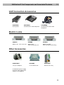
1
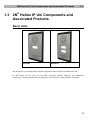
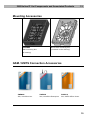
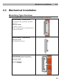
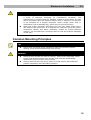
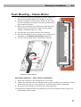
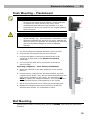
®
2N Helios IP Uni
Door Access Intercom
Installation Manual
Version:
1.0.0
www.2n.cz
The 2N TELEKOMUNIKACE a.s. joint-stock company is a Czech manufacturer and supplier
of telecommunications equipment.
The product family developed by 2N TELEKOMUNIKACE a.s. includes intercoms, GSM and
UMTS products, private branch exchanges (PBXs) and M2M solution.
2N TELEKOMUNIKACE a.s. has been ranked among the Czech top companies for years
and represents a symbol of prosperity in the field of IP intercoms. Furthermore, the
company dedicates significant attention to operator solutions as well as to effectively
providing support for our distribution network and customer service. At present, we
export our products into over 120 countries worldwide and have exclusive distributors on
all continents.
2N® is a registered trademark of 2N TELEKOMUNIKACE a.s.. Any product and/or other
names mentioned herein are registered trademarks and/or trademarks or brands
protected by law.
2N TELEKOMUNIKACE administers the FAQ database to help you quickly find information
and to answer your questions about 2N products and services. On faq.2n.cz you can find
information regarding products adjustment and instructions for optimum use and
procedures „What to do if...“.
Declaration of Conformity
2N TELEKOMUNIKACE a.s. hereby declares that the 2N® Helios IP Uni product complies
with all basic requirements and other relevant provisions of the 1999/5/EC directive. For
the full wording of the Declaration of Conformity see the CD-ROM enclosed and at www.2n.cz.
2N TELEKOMUNIKACE company is the owner of the ISO 9001:2008 certificate. All
development, production and distribution processes of the company are managed by this
standard and guarantee high quality, technical level and professional aspect of all our
products.
Contents
1. Product Overview............................................................... 5
1.1
Product Description ....................................................................................................... 6
Basic Features.................................................................................................................. 6
Advantages of Use ........................................................................................................... 7
1.2
Upgrade ........................................................................................................................... 8
1.3
2N Helios IP Uni Components and Associated Products......................................... 9
Basic Units ........................................................................................................................ 9
Mounting Accessories .................................................................................................... 10
GSM / UMTS Connection Accessories .......................................................................... 10
VoIP Connection Accessories ........................................................................................ 11
Electric Locks ................................................................................................................. 11
Other Accessories .......................................................................................................... 11
1.4
Terms and Symbols ..................................................................................................... 12
Symbols .......................................................................................................................... 12
®
2. Description and Installation ............................................ 13
2.1
Before You Start ........................................................................................................... 14
Product Completeness Check ........................................................................................ 14
2.2
Mechanical Installation ................................................................................................ 15
Mountiong Type Overview.............................................................................................. 15
Common Mounting Principles ........................................................................................ 16
Flush Mounting – Classic Bricks .................................................................................... 17
Flush Mounting – Plasterboard ...................................................................................... 18
Wall Mounting ................................................................................................................. 18
Electric Installation ......................................................................................................... 19
PCB Connectors ............................................................................................................. 19
2.3
Button Tags – Insertion and Replacement ................................................................ 21
Tag Printing .................................................................................................................... 21
Tag Inserting / Replacing vložit nový obr. ...................................................................... 21
3. Function and Use ............................................................. 23
®
3.1
2N Helios IP Uni Configuration ................................................................................. 24
3.2
2N Helios IP Uni Control ............................................................................................ 25
Speed Dial Buttons ......................................................................................................... 25
3.3
Maintenance .................................................................................................................. 26
Cleaning ......................................................................................................................... 26
Future Tag Replacement, Programming Changes ........................................................ 26
®
4. Technical Parameters ...................................................... 27
4.1
Technical Parameters .................................................................................................. 29
5. Supplementary Information ............................................ 30
5.1
Directives, Laws and Regulations .............................................................................. 31
5.2
Troubleshooting ........................................................................................................... 32
5.3
General Instructions and Cautions ............................................................................ 33
Electric Waste and Used Battery Pack Handling ........................................................... 34
1
1.
Product
Overview
In this section, we introduce the 2N® Helios IP Uni product, outline its application
options and highlight the advantages following from its use.
Here is what you can find in this section:
Product Description
Upgrade
2N® Helios IP Uni Components and Associated Products
5
Product Description
1.1
1.1 Product Description
Basic Features
2N® Helios IP Uni is a highly resistant and reliable IP door access intercom provided
with a lot of useful above-standard functions. Supporting the SIP standard and being
compatible with the leading IP PBX and telephone suppliers, 2N® Helios IP Uni can
make use of all VoIP services. 2N® Helios IP Uni can work as a standard or emergency
door access intercom for buildings, entrances to premises or garages, manufacturing
halls, highways and so on.
2N® Helios IP Uni is equipped with a loudspeaker (1W). Thanks to an integrated
acoustic echo cancelling (AEC) system, the product provides mutual audibility even of
persons talking at the same time under normal conditions.
2N® Helios IP Uni can be provided with 1 or 2 pre-programmed buttons. You can set
up to three telephone numbers and time profiles for each of the buttons to increase
the accessibility of the called party.
2N® Helios IP Uni is equipped with an electric lock switch. You can control the switch
during a call, using any telephone set.
2N® Helios IP Uni is very easy to install. All you have to do is connect the system
into your LAN via a network cable and feed it from a 12V power supply or your PoE
supporting LAN.
Configure 2N® Helios IP Uni using your PC via any web browser. Use the
2N® Helios IP Manager to manage extensive 2N® Helios IP Uni systems easily and
quickly.
6
Product Description
1.1
Advantages of Use
Variable mounting options (brick/plasterboard flush mounting, wall mounting)
Sensitive microphone and powerful loudspeaker
Bidirectional communication – acoustic echo cancelling
Optional dial buttons including name tags and backlight
Integrated electronic lock switches with wide setting options
LAN (PoE) or external 12V power supply
Configuration via web interface or dedicated PC application
SIP 2.0 support
HTTP server for configuration
SNTP client for time synchronisation with server
7
Upgrade
1.2
1.2 Upgrade
The manufacturer reserves the right to modify the product in order to improve its
qualities.
Version Changes
8
2N® Helios IP Uni Components and Associated Products
1.3
1.3 2N® Helios IP Uni Components and
Associated Products
Basic Units
9153101
9153102
2N® Helios IP Uni is designed for outdoor applications and requires no additional roof.
All 2N® Helios IP Uni units can be flush mounted without requiring any additional
accessories. Use the appropriate mounting box (see below) for wall (surface) mounting.
9
2N® Helios IP Uni Components and Associated Products
1.3
Mounting Accessories
9153003
Brick flush mounting box
Wall mounting box
(included in the delivery)
(Al casting)
GSM / UMTS Connection Accessories
505004
505214
505612
2N® VoiceBlue Lite
2N® VoiceBlue Enterprise
2N® UMTS Office Route
10
2N® Helios IP Uni Components and Associated Products
1.3
VoIP Connection Accessories
91378100
91378300
91378350
PoE injector
Grandstream VoIP telephone
Grandstream VoIP video
telephone
Electric Locks
932070
932080
932090
BEFO 1211 12V / 600 mA
BEFO 1221
with momentary pin
BEFO 1211MB
with mechanical blocking
Other Accessories
91341481E
932928E
9137410E
12 V/2 A adapter
12 V transformer
External IP relay
A stabilised power supply
must be used where PoE
supply is not applied.
11
Terms and Symbols
1.4
1.4 Terms and Symbols
Symbols
Safety Warning
Always abide by this information to prevent injury of persons!
Warning
Always abide by this information to prevent damage to the device.
Caution
Important information for system functionality.
Tip
Useful advice.
Note
Additional information.
12
2
2.
Description and
Installation
In this section we describe the 2N® Helios IP Uni product and its installation.
Here is what you can find in this section:
Before You Start
Mechanical Installation
Button Tags – Insertion and Replacement
Electric Installation
13
Before You Start
2.1
2.1 Before You Start
Product Completeness Check
Please check the contents of your 2N® Helios IP Uni delivery:
1 2N® Helios IP Uni (selected model)
1 Torx 10 / Torx 20 double-ended wrench
1 2N® Helios IP Uni Installation Manual
1 mounting template
1 CD
1 A5 transparent name plate foil
1 spare name plate
1 brick flush mounting box
4 4x12 stainless steel, torx screws for plastics
2 cable ties
14
Mechanical Installation
2.2
2.2 Mechanical Installation
Mountiong Type Overview
Refer to the table below for a list of mounting types and necessary components.
Flush mounting – classic bricks
(also hollow bricks, thermally insulated
walls, etc.)
What you need:
A properly cut hole
Plaster, mounting glue, mounting foam or
mortar as necessary
Flush mounting – plasterboard
What you need:
Just a properly curt hole
Wall mounting (concrete and steel
structures, entry barrier columns, etc.)
What you need:
Wall mounting box
Part No. 9153003
15
Mechanical Installation
2.2
Caution
The warranty does not apply to the product defects and failures arisen as
a result of improper mounting (in contradiction herewith). The
manufacturer is neither liable for damage caused by theft within an area
that is accessible after the attached electric lock is switched. The product
is not designed as a burglar protection device except when used in
combination with a standard lock, which has the security function.
When the proper mounting instructions are not met, water might get in
and destroy the electronics. It is because the intercom circuits are under
continuous voltage and water infiltration causes an electro-chemical
reaction. The manufacturer’s warranty shall be void for products damaged
in this way!
Common Mounting Principles
Tip
Select flush mounting where possible to make your product elegant
looking, more vandal resistant and more secure.
Caution
Stainless steel screws are used for the 2N® Helios IP Uni assembly. Other
screws than stainless steel ones corrode soon and may aesthetically
deteriorate the surrounding environment!
Having removed the front panel, make sure that no dirt gets inside the
product (especially onto the sealing surface).
16
Mechanical Installation
2.2
Flush Mounting – Classic Bricks
1. Cut a wall hole using the template enclosed. Make sure
that all the required cables are available in the hole.
2. Unpack the plastic mounting box. Break out the cable
holes as necessary and make sure that the wall hole is
big enough for the box.
3. Wall up the mounting box making sure that the box is
aligned with the wall surface. Wait until the plaster
(mortar, mounting foam, etc.) sets.
4. Unscrew the front panel from the door intercom.
5. Connect the cables to the terminals or RJ connector as
described in the Electric Connection subsection.
6. You can use the cable tie for connection as shown:
Suggested cable fixation
Mounting completion – after electric installation!
7. Insert the intercom in the mounting box in the wall.
8. Tighten the intercom with the stainless steel screws included in the delivery. As the
screw holes are oval, you can perfect the vertical position before tightening.
9. We do not recommend you to insert the button tags now.
10. Replace the stainless steel front panel fixing it with the stainless steel screws you
unscrewed in step 4 above.
17
Mechanical Installation
2.2
Flush Mounting – Plasterboard
Tip
If this is your first plasterboard installation, check the
function of the intercom side clamps. Loosen and then
re-tighten the clamp screw to see how it turns
automatically and starts moving forwards in its slot.
Remember to return the clamp into the original position
after the check!
Caution
Check the plasterboard wall and room interior pressure
values (caused, e.g., by overpressure ventilation). If the
difference between the values is too great, separate the
intercom using, for example, the mounting box enclosed
and seal the cable passage to avoid loudspeaker
damage.
1. Cut a hole using the template enclosed (165 x 95 mm).
2. Unscrew the front panel from the door intercom.
3. Connect the cables in the hole to the terminals or RJ
connector as described in the Electric Connection
subsection.
4. You can use the cable tie for connection as shown on
previous page.
Mounting completion – after electric installation!
5. Insert the intercom in the hole keeping it in the vertical
position.
6. Loosen the four clamp screws one after another and then
retighten them slowly. They will turn aside automatically and
start moving forwards in their slots. You need about 10
turns to tighten the clamps completely. You can perfect the
vertical position before final tightening of the screws.
7. We do not recommend you to insert the button tags now.
8. Replace the stainless steel front panel fixing it with the
stainless steel screws you unscrewed in step 2.
Wall Mounting
Use the wall (surface) mounting box, part No. 9153003, and follow the instructions
enclosed.
18
Electric Installation
2.3
2.3 Electric Installation
This subsection describes how to connect 2N® Helios IP Uni into your Local Area
Network (LAN) and how to connect supply voltage and the electric lock.
PCB Connectors
Description of Connectors
LAN
LAN connector
OUT1
12V/700 mA switched
output
RELAY1
Relay NO/NC contacts
TAMPER
Tamper switch
POWER
12V/1A DC power input
RESET
RESET button
19
Electric Installation
2.3
LAN Connection
2N® Helios IP Uni is connected to the LAN via a RJ-45 terminated (connector X11)
UTP/STP cable (of category Cat 5e or higher). The system is equipped with the AutoMDIX function and so both the straight and crossed cable versions can be used
External Power Supply Connection
2N® Helios IP Uni can be fed either from an external 12V/1A DC power supply or from
the LAN equipped with the PoE 802.3af supporting network elements.
External Power Supply
An external 12V power supply is connected to terminal block X19. Use a 12V +- 15%
DC power source dimensioned to current intake of 1A at least (Part No. 91341481E) to
ensure a reliable function of your device.
PoE Supply
2N® Helios IP Uni is compatible with the PoE 802.3af (Class 0 – 12.95W) technology
and can be supplied directly from the LAN via compatible network elements. If your
LAN in incompatible, insert the PoE injector, Part No. 91758100E, between
2N® Helios IP Uni and the nearest network element.
Electric Lock Connection
2N® Helios IP Uni is equipped with an electrically isolated relay switch with NO and NC
contacts (terminal block X17) and 12V/700mA switched output (terminal block X18),
to which a standard electric lock or another compatible electrical appliance can be
connected.
Device Resetting
2N® Helios IP Uni is equipped with a RESET button. Push the button for more than 10s
to reset the factory default values, deleting all the data stored in the device. Push the
button shortly (< 1s) to restart the device without changing its configuration.
20
Button Tags – Insertion and Replacement
2.4
2.4 Button Tags – Insertion and
Replacement
Tag Printing
1.
Every name plate includes a piece of foil, which can be written over manually,
using a waterproof permanent marker.
Note
Always use waterproof foil (enclosed or other) for the tags. Never use
paper or ink jet printing to avoid damage due to water leakage!
Tag Inserting / Replacing
2N® Helios IP Uni provides an intuitive, easy
access to the name plates. The tags are easy
to insert and replace even without a manual.
You need not remove the front panel and
thus are not exposed to the risk of loss of
components while replacing the tags.
1. Loosen the name plate screw using
the wrench enclosed, for example.
You can open the name plate window
like a door without losing the
tightened screw.
2. Remove the used or blank name tag
and insert a new tag.
3. Close the name plate window and
tighten the screw appropriately.
4. Check the click effect of the buttons:
if the button fails to click properly
when pressed (when moved by
approx. 0.5 mm), the tag is too thick
or thin. Make sure that the button
clicks when you press it on either
end.
21
3
3.
Function and
Use
In this section we describe the basic and extending functions of the 2N® Helios IP
Uni product.
Here is what you can find in this section:
2N® Helios IP Uni Configuration
2N® Helios IP Uni
Maintenance
23
2N® Helios IP Uni Configuration
3.1
3.1 2N® Helios IP Uni Configuration
2N® Helios IP Uni Use a PC equipped with any web browser to configure:
Launch your web browser (Internet Explorer, Firefox, etc.).
Enter the IP address of your intercom (http://192.168.1.100/, e.g.).
Log in using the Admin user name and 2n password.
You have to know the IP address of your device to log in to the integrated web server.
By default, 2N® Helios IP Uni is switched into the dynamic IP address mode, i.e. it
obtains the IP address automatically if a properly set DHCP server is available in your
LAN. If no such DHCP server is available, you can operate 2N® Helios IP Uni in the
static IP address mode. Refer to the 2N® Helios IP Configuration Manual for
configuration details.
If your device remains inaccessible (you have forgotten the IP address, or the LAN
configuration has changed, for example), change the LAN settings using the buttons
on the device.
Static/Dynamic Address Setting Mode Switching
In case your 2N® Helios IP Uni device is equipped with 1 or 2 buttons, you can switch
the modes using one button only.
Connect 2N® Helios IP Uni to the power supply (or, disconnect and reconnect
it if already connected).
Wait for the first acoustic signal
Press button 1 fifteen times.
The acoustic signal
Wait until the device is restarted automatically.
.
indicates mode switching.
Note: The 15-times-1 sequence must be entered within 30 seconds after the first
sound signal for security reasons. The inter-digit delay may be 2s at most
The static IP address mode will be switched into the dynamic IP address mode and
vice versa upon restart.
24
2N® Helios IP Uni Control
3.2
3.2 2N® Helios IP Uni Control
This subsection describes how to control 2N® Helios IP Uni when viewed by an
external user.
Speed Dial Buttons
Press the speed dial buttons on the basic unit to make quick dialling for the first 1 or 2
(depending on the model type) in the telephone directory. Call setup is signalled by a
long intermittent tone or otherwise as configured in the PBX connected.
Repeated pressing of one and the same speed dial button during call setup may
initiate call termination, or call termination plus dialling the next telephone number of
the called subscriber, or may be assigned no function.
25
Maintenance
3.3
3.3 Maintenance
Cleaning
If used frequently, 2N® Helios IP Uni gets dirty. To clean it, use a piece of soft cloth
moistened with clean water. We recommend you to obey the following principles while
cleaning:
Never use aggressive detergents (such as abrasives or strong disinfectants).
Alcohol-based cleaners may be applied.
Clean the device in dry weather in order to make waste water evaporate
quickly.
Future Tag Replacement, Programming Changes
For necessary steps refer to the preceding subsections. Keep the following for future
changes:
This manual
Unused transparent foil strips for button tags
Always use the product for the purpose it was designed and manufactured for, in
compliance herewith.
The manufacturer reserves the right to modify the product in order to improve its
qualities.
2N® Helios contains no environmentally harmful components. When the product‘s
service life is exhausted and you would like to dispose of it please do so in accordance
with applicable legal regulations.
26
4
4.
Technical
Parameters
In this section we describe the technical parameters of the 2N® Helios IP Uni
product.
27
4.1 Technical Parameters
Signalling protocol
SIP (UDP)
Buttons
Button design
Transparent, white backlit buttons with easily
replaceable name tags
Button count
1 or 2
Microphone
1 integrated microphone
Amplifier
1W (class D)
Loudspeaker
1W
Audio
Volume control
Adjustable with automatic adaptive mode
Full duplex
Yes (AEC)
Audio stream
Protocols
RTP/RTSP
Codecs
G.711
Interfaces
Power supply
12V+-15%/1A DC or PoE
PoE
PoE 802.3af (Class 0 - 12.95W)
LAN
10/100BASE-TX s Auto-MDIX, RJ-45
Recommended cabling Cat-5e or higher
Passive switch
NO and NC contacts, up to 30V/1A AC/DC
Active switch output
12V/700mA DC
Mechanical properties
Cover
ABS plastic, high-quality stainless steel
Working temperature
Working relative
humidity
-40°C to 55°C
Storing temperature
Dimensions
Weight
Covering level
10% to 95% (non-condensing)
-40°C to 70°C
193 x 115 x 39 mm
197 x 119 x 47 mm with flush mounting box
193 x 115 x 57 mm for wall mounting
Product net weight....... 500 g
Mounting box ....... 135 g
Total weight incl. package ... 800 g
IP54
29
5
5.
Supplementary
Information
This section provides supplementary information on the 2N® Helios IP Uni product.
Here is what you can find in this section:
Applicable Directives, Laws and Regulations
30
Directives, Laws and Regulations
5.1
5.1 Directives, Laws and Regulations
2N® Helios IP Uni conforms to the following directives and regulations:
Directive 1999/5/EC of the European Parliament and of the Council, of 9
March 1999 – on radio equipment and telecommunications terminal
equipment and the mutual recognition of their conformity
Directive 2006/95/EC of the European Parliament and of the Council of 12
December 2006 on the harmonisation of the laws of Member States relating
to electrical equipment designed for use within certain voltage limits
Directive 2004/108/EC of the Council of 15 December 2004 on the
harmonisation of the laws of Member States relating to electromagnetic
compatibility
Directive 2002/95/EC of the European Parliament and of the Council of
27 January 2003 on the restriction of the use of certain hazardous substances
in electrical and electronic equipment
Regulation (EC) No. 1907/2006 of the European Parliament and of the
Council of 18 December 2006 concerning the Registration, Evaluation,
Authorisation and Restriction of Chemicals (REACH), establishing a European
Chemicals Agency, amending Directive 1999/45/EC and repealing Council
Regulation (EEC) No. 793/93 and Commission Regulation (EC) No. 1488/94
as well as Council Directive 76/769/EEC and Commission Directives
91/155/EEC, 93/67/EEC, 93/105/EC and 2000/21/EC
Directive 2002/96/EC of the European Parliament and of the Council of 27
January 2003 on waste electrical and electronic equipment.
Commission Regulation (EC) No. 1275/2008, of 17 December 2008,
implementing Directive 2005/32/EC of the European Parliament and of the
Council with regard to ecodesign requirements for standby and off mode
electric power consumption of electrical and electronic household and office
equipment
31
Troubleshooting
5.2
5.2 Troubleshooting
For tips concerning solutions of other potential problems see faq.2n.cz.
32
General Instructions and Cautions
5.3
5.3 General Instructions and Cautions
Please read this User Manual carefully before using the product. Follow all instructions
and recommendations included herein.
Any use of the product that is in contradiction with the instructions provided herein
may result in malfunction, damage or destruction of the product.
The manufacturer shall not be liable and responsible for any damage incurred as a
result of a use of the product other than that included herein, namely undue
application and disobedience of the recommendations and warnings in contradiction
herewith.
Any use or connection of the product other than those included herein shall be
considered undue and the manufacturer shall not be liable for any consequences
arisen as a result of such misconduct.
Moreover, the manufacturer shall not be liable for any damage or destruction of the
product incurred as a result of misplacement, incompetent installation and/or undue
operation and use of the product in contradiction herewith.
The manufacturer assumes no responsibility for any malfunction, damage or
destruction of the product caused by incompetent replacement of parts or due to the
use of reproduction parts or components.
The manufacturer shall not be liable and responsible for any loss or damage incurred
as a result of a natural disaster or any other unfavourable natural condition.
The manufacturer shall not be held liable for any damage of the product arising during
the shipping thereof.
The manufacturer shall not make any warrant with regard to data loss or damage.
The manufacturer shall not be liable and responsible for any direct or indirect damage
incurred as a result of a use of the product in contradiction herewith or a failure of the
product due to a use in contradiction herewith.
All applicable legal regulations concerning the product’s installation and use as well as
provisions of technical standards on electric installations have to be obeyed. The
manufacturer shall not be liable and responsible for damage or destruction of the
product or damage incurred by the consumer in case the product is used and handled
contrary to the said regulations and provisions.
The consumer shall, at its own expense, obtain software protection of the product. The
manufacturer shall not be held liable and responsible for any damage incurred as a
result of the use of deficient or substandard security software.
The consumer shall, without delay, change the access password for the product after
installation. The manufacturer shall not be held liable or responsible for any damage
incurred by the consumer in connection with the use of the original password.
The manufacturer also assumes no responsibility for additional costs incurred by the
consumer as a result of making calls using a line with an increased tariff.
33
General Instructions and Cautions
5.3
Electric Waste and Used Battery Pack Handling
Do not place used electric devices and battery packs into municipal waste containers.
An undue disposal thereof might impair the environment!
Deliver your expired electric appliances and battery packs removed from them to
dedicated dumpsites or containers or give them back to the dealer or manufacturer for
environmental-friendly disposal. The dealer or manufacturer shall take the product
back free of charge and without requiring another purchase. Make sure that the
devices to be disposed of are complete.
Do not throw battery packs into fire. Battery packs may not be taken into parts or
shirt-circuited either.
34
2N TELEKOMUNIKACE a.s.
Modřanská 621, 143 01 Prague 4, Czech Republic
Tel.: +420 261 301 500, Fax: +420 261 301 599
E-mail: [email protected]
Web: www.2n.cz
DR1812v1.0