1
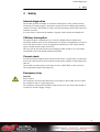
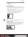
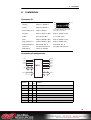
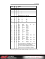
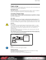
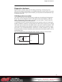
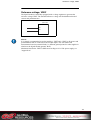
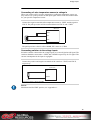
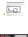
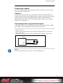
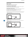
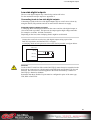
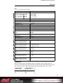
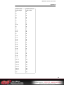
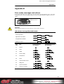
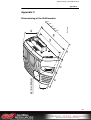
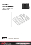
IQAN-MC2
Instruction book
Publ no HY33-8388-IB/UK
Edition 2013-07-30
Contents
1
Introduction . . . . . . . . . . . . . . . . . . . . . . . . . . . . . . . . . . . . . . . . . . . . . . . . . . . . 1
Warnings . . . . . . . . . . . . . . . . . . . . . . . . . . . . . . . . . . . . . . . . . . . . . . . . . . . . 1
Overview of relevant documentation . . . . . . . . . . . . . . . . . . . . . . . . . . . . . . . 2
2
Precautions . . . . . . . . . . . . . . . . . . . . . . . . . . . . . . . . . . . . . . . . . . . . . . . . . . . . 3
Read This . . . . . . . . . . . . . . . . . . . . . . . . . . . . . . . . . . . . . . . . . . . . . . . . . . . . 3
3
Product description . . . . . . . . . . . . . . . . . . . . . . . . . . . . . . . . . . . . . . . . . . . . . 5
IQAN-MC2 . . . . . . . . . . . . . . . . . . . . . . . . . . . . . . . . . . . . . . . . . . . . . . . . . . . 5
4
Safety . . . . . . . . . . . . . . . . . . . . . . . . . . . . . . . . . . . . . . . . . . . . . . . . . . . . . . . . . 8
Internal diagnostics . . . . . . . . . . . . . . . . . . . . . . . . . . . . . . . . . . . . . . . . . . . . 8
CAN-bus interruption . . . . . . . . . . . . . . . . . . . . . . . . . . . . . . . . . . . . . . . . . . . 8
Current check . . . . . . . . . . . . . . . . . . . . . . . . . . . . . . . . . . . . . . . . . . . . . . . . . 8
Emergency stop . . . . . . . . . . . . . . . . . . . . . . . . . . . . . . . . . . . . . . . . . . . . . . . 8
5
Mounting . . . . . . . . . . . . . . . . . . . . . . . . . . . . . . . . . . . . . . . . . . . . . . . . . . . . . . 9
Mounting the module . . . . . . . . . . . . . . . . . . . . . . . . . . . . . . . . . . . . . . . . . . . 9
6
Installation . . . . . . . . . . . . . . . . . . . . . . . . . . . . . . . . . . . . . . . . . . . . . . . . . . . . 10
Supply voltage . . . . . . . . . . . . . . . . . . . . . . . . . . . . . . . . . . . . . . . . . . . . . . . 12
Addressing/terminating . . . . . . . . . . . . . . . . . . . . . . . . . . . . . . . . . . . . . . . . 13
Diagnostic interfaces . . . . . . . . . . . . . . . . . . . . . . . . . . . . . . . . . . . . . . . . . . 14
Reference voltage, VREF . . . . . . . . . . . . . . . . . . . . . . . . . . . . . . . . . . . . . . 16
Voltage inputs . . . . . . . . . . . . . . . . . . . . . . . . . . . . . . . . . . . . . . . . . . . . . . . 17
Digital inputs . . . . . . . . . . . . . . . . . . . . . . . . . . . . . . . . . . . . . . . . . . . . . . . . . 20
Frequency inputs . . . . . . . . . . . . . . . . . . . . . . . . . . . . . . . . . . . . . . . . . . . . . 22
Proportional outputs . . . . . . . . . . . . . . . . . . . . . . . . . . . . . . . . . . . . . . . . . . . 23
Connecting loads to proportional outputs . . . . . . . . . . . . . . . . . . . . . . . . . . . 23
Digital outputs . . . . . . . . . . . . . . . . . . . . . . . . . . . . . . . . . . . . . . . . . . . . . . . 24
Low-side digital outputs . . . . . . . . . . . . . . . . . . . . . . . . . . . . . . . . . . . . . . . . 25
7
Start-up . . . . . . . . . . . . . . . . . . . . . . . . . . . . . . . . . . . . . . . . . . . . . . . . . . . . . . . 26
Start-up procedures . . . . . . . . . . . . . . . . . . . . . . . . . . . . . . . . . . . . . . . . . . . 26
8
System Diagnostics . . . . . . . . . . . . . . . . . . . . . . . . . . . . . . . . . . . . . . . . . . . . 27
Safe mode . . . . . . . . . . . . . . . . . . . . . . . . . . . . . . . . . . . . . . . . . . . . . . . . . . 28
Appendix A . . . . . . . . . . . . . . . . . . . . . . . . . . . . . . . . . . . . . . . . . . . . . . . . . . . 29
IQAN-MC2 Technical Overview . . . . . . . . . . . . . . . . . . . . . . . . . . . . . . . . . . 29
Appendix B . . . . . . . . . . . . . . . . . . . . . . . . . . . . . . . . . . . . . . . . . . . . . . . . . . . 34
Error codes, messages and actions . . . . . . . . . . . . . . . . . . . . . . . . . . . . . . . 34
Appendix C . . . . . . . . . . . . . . . . . . . . . . . . . . . . . . . . . . . . . . . . . . . . . . . . . . . 35
Dimensioning of the IQAN module . . . . . . . . . . . . . . . . . . . . . . . . . . . . . . . . 35
Instruction book, IQAN-MC2
ii
Warnings
1
1
Introduction
Introduction
These instructions are to be used as a reference tool for the vehicle manufacturer’s
design, production, and service personnel.
The user of these instructions should have basic knowledge in the handling of
electronic equipment.
Warnings
Sections marked with a symbol in the left margin, must be read and understood by
everyone using the system, carrying out service work, or making changes to hardware
and software.
The different symbols used in this manual are defined below.
WARNING
Sections labeled WARNING with a caution symbol in the left margin, indicate that a
hazardous situation exists. We use warnings, marked with the warning symbol, in two
ways.
• As a strong recommendation about work practices when using the product in the
machine (e.g. routines when updating an application). This use is common to the
term 'hazardous situation', that a person is exposed to a hazard.
• As a way of pointing out important information for the machine designer that in
some way relates to safety. This includes the design of the physical machine, and
also the application program being developed for the control system.
Not all document sections that contain information about safety are marked with a
warning symbol (there would be warnings everywhere). Failure to comply with the
recommendations can cause unintentional, and unexpected behavior of the control
system. This can potentially cause death, serious injury or property damage.
N OTICE
Sections labeled NOTICE with a notice symbol in the left margin, indicate there is
important information about the product. Ignoring this could result in less than optimal
performance, or damage to the product.
Contact the manufacturer if there is anything you are not sure about or if you have any
questions regarding the product and its handling or maintenance.
The term "manufacturer" refers to Parker Hannifin Corporation.
Instruction book, IQAN
1
Overview of relevant documentation
1
Introduction
Overview of relevant documentation
The following publications are relevant for users of this product.
The main documentation contains information that is not found elsewhere.
The additional documentation contains product information in a compact format, for
details on the information found in those documents, consult this manual.
Main
Documentation
Compact
Documentation
IQANdesign/
IQANrun
User Manuals
IQAN module
Instruction Book
HY33-8nnn-IB
IQAN module
Catalogue Datasheet
HY33-8nnn
Mounting and Maintenance
Instruction Book
HY33-8327-IB
IQAN module
Installation Sheet
HY33-8nnn-IS
IQAN module
Electrical Schematic
HY33-8nnn-ES
The IQAN module documentation system.
2
Instruction book, IQAN
Read This
2
2
Precautions
Precautions
Work on the hydraulics control electronics may only be carried out by trained
personnel who are well-acquainted with the control system, the machine and its safety
regulations.
WARNING
Make sure that you have sufficient knowledge before designing, modifiying or
servicing the control system.
Read the relevant sections of this document before conducting any work on the control
system.
WARNING
This product is not field repairable.
N OTICE
As much as possible of the welding work on the chassis should be done before the
installation of the system. If welding has to be done afterwards, the electrical
connections on the system must be disconnected from other equipment. The negative
cable must always be disconnected from the battery before disconnecting the positive
cable. The ground wire of the welder shall be positioned as close as possible to the
place of the welding. The cables on the welding unit shall never be placed near the
electrical wires of the control system.
Read This
Design of control system
WARNING
Risk of injury may be introduced by design of control system!
This product is designed to control hydraulic outputs. The control application must be
designed using basic safety principles so that unintentional movement is avoided.
The machine must be equipped with an emergency stop that stops all movement. Please
refer to section "Supply voltage".
Before you start
Read this document.
Read the IQANdesign software user manual section on 'application safety'.
3
Instruction book, IQAN
Read This
2
Precautions
Start-up, maintenance, and diagnostics
For all personnel carrying out installation, commissioning, maintenance or
troubleshooting.
WARNING
Work on the hydraulics control electronics may only be carried out by trained
personnel who are well-acquainted with the control system, the machine and its safety
regulations.
Before you start,
Read section "Start-up".
Additional information for service
Mounting and maintenance instruction book.
Additional information for diagnosing the system
Read section "System diagnostics", and see "Appendix B", in this document.
Use the IQANrun software user manual as a reference.
4
Instruction book, IQAN
IQAN-MC2
3
3
Product description
Product description
IQAN-MC2
The IQAN-MC2 is designed for controlling hydraulic systems in vehicles and
machinery, using 12/24 Vdc power supply.
IQAN-MC2 is a master unit capable of running applications created by IQANdesign.
The MC2 has local I/O for input/output use and has two CAN busses that support ICP
(IQAN CAN Protocol), SAE J1939 and Generic CAN.
By supporting SAE J1939 and Generic CAN the MC2 can act as a sub-master when
there is a need of higher performance in a sub-circuit or when there is an OEM supplied
overall machine master.
This product is designed for the outdoor environment and comes with an IP6K9K
protection for applications where high-pressure water and steam jet cleaning is used.
The IQAN-MC2 module.
I/O overview
+BAT
ADDR-H
-BAT
ADDR-L
+VREF
CAN-H
-VREF
CAN-L
MC2
USB
PORT 0
CAN-H
CAN-L
PORT 1
5
Instruction book, IQAN-MC2
IQAN-MC2
3
Product description
Inputs
The IQAN-MC2 module has five (5) voltage inputs VIN-A thru VIN-E for connection
of 0-5 Vdc signals. The inputs are multi-purpose and for flexibility may be configured
in other ways. The input pins VIN-A and VIN-E can be configured as on/off inputs for
switches or as frequency inputs for measuring frequency. Voltage inputs, on/off inputs
and frequency inputs share positions, see list.
(5) Voltage inputs VIN-A thru VIN-E
or
(5) Frequency inputs FIN-A thru FIN-E use positions VIN-A thru VIN-E.
or
(5) Digital inputs DIN-A thru DIN-E use positions VIN-A thru VIN-E.
Proportional outputs
The MC2 module has eight (8) double proportional outputs for controlling proportional
valves. These outputs can control eight bi-directional valve sections or eight single
solenoid devices (ie. proportional cartridge valves). The proportional outputs can be
used in two different modes. Either Current mode (current closed loop) or PWM mode
(voltage open loop) signals can be selected and the parameters configured using IQAN
software.
For flexibility these outputs may also be configured as up to eight (8) on/off outputs and
up to eight (8) on/off inputs or voltage inputs. Additional functionality for these
positions is as up to sixteen (16 ) low-side on/off outputs. The proportional outputs, on/
off outputs, on/off or voltage inputs and low-side on/off outputs share positions, see
below.
(8) double proportional outputs COUT-A thru COUT-H
or
(8) double proportional outputs PWMOUT-A thru PWMOUT-H
or
(8) on/off outputs DOUT-A thru DOUT-H.
Each pair of return pins may then be used as:
(2) low-side digital output switches (16) total, DOUT(LS)-I thru DOUT(LS)-X.
It is recommended to use one or more of DOUT-A thru DOUT-H as source if
used in this manner, for safety.
The pairs of return pins associated with DOUT-E thru DOUT-H may also be
used as:
(2) on/off inputs, (8) total, DIN-F thru DIN-M.
(2) voltage inputs, (8) total, VIN-F thru VIN-M.
In order to increase the performance of the proportional outputs when controlling
proportional valves, the dither frequency can be adjusted.
6
Instruction book, IQAN-MC2
IQAN-MC2
3
Product description
CAN related functions
The IQAN-MC2 uses a CAN-bus (CAN = Controller Area Network) to communicate
with IQAN expansion modules and other systems. The CAN-bus is a robust
communication protocol that is widely used and well proven within the automotive
industry.
The unit has two (2) CAN buses, CAN-A and CAN-B. The buses may be configured
using IQAN software to be ICP (ICP = IQAN CAN Protocol), SAE J1939 or Generic
user defined CAN protocol (e.g. CANopen).
Communication
The communication interfaces are used for uploading/downloading applications or
diagnostics and typically are connected to a computer.
CAN
The IQAN-MC2 has 2 CAN buses. Either of the CAN buses may be used for
communication and diagnostics. A CAN communication card is required to be installed
in your PC to use this feature.
USB
The IQAN-MC2 has a USB1.1 (device only) connection in connector C1, for
maximum voltage on USB pins, see Appendix A.
7
Instruction book, IQAN-MC2
Internal diagnostics
4
4
Safety
Safety
Internal diagnostics
The module performs a number of self-checks that improve safety. Checks include
monitoring of voltage supplies, checksums on memory and a watchdog that monitors
software execution. The module is using a real time operating system which supervises
software execution.
If a critical error is detected, the module is stopped, with CAN-bus and outputs off.
CAN-bus interruption
The IQAN modules communicate on a CAN-bus. Both the master module and
expansion modules check for any interruptions in CAN-bus communication. If an error
occurs the master will use zero or an application defined error value for the module
inputs, and the module outputs will be off.
The error will be presented on the master/display module, if there is one, and with a
related blink code on the IQAN module status LEDs.
Current check
For the proportional outputs when used in current mode, a current check is performed.
If an error is detected, this will be indicated on the master module, and the output will
shut off.
The module can detect open-circuit, short-circuit to +BAT/-BAT or short-circuit to
other proportional output and return pins.
Emergency stop
WARNING
Risk of injury!
The emergency stop must disconnect the power supply to the module; do not connect
the emergency stop as a signal input only.
The emergency stop must be installed so that the risk of reverse feed of the module is
avoided, see section "Supply voltage".
8
Instruction book, IQAN
Mounting the module
5
5
Mounting
Mounting
Mounting the module
The IQAN module should be mounted according to the following instructions:
• Locate the module eliminating the risk for the cabling to be folded, crushed or damaged in any way. Ensure the cabling cannot pull, twist or induce sideload on the connector.
• Locate the module so that severe physical impact is avoided, e.g impact from falling
objects or the module being used as a step.
• Locate the module so that air can circulat to eliminate excess heat. Ensure that no
external heat, e.g. from the engine or heater, is transferred to the module.
• Locate the module to protect it from high pressure washing or similar.
• Locate the module so that the cable connector is facing down .
• Locate the module so that the LEDs are visible.
Non approved placing.
N OTICE
The IQAN module must not be placed in any marine related or similar continuously
damp, salt-spray environment without external protection.
Assembling of the ID-Tag
The ID-Tag will be placed in the connector in order to address/ terminate the module.
For IQAN master modules, the use of an ID-tag is application dependant. All IQAN
expansion modules require an ID-tag, ref section "Addressing/terminating".
The ID-Tag will be mounted under the connector casing. Bend the ID-Tag’s wires
toward the opposite side of where the other wires enter the connector.
Assembling of the Id-Tag.
9
Instruction book, IQAN
6
6
Installation
Installation
Connector C1
Connector kit
Parker no. 5031063
Housing
Amp no. 1-963226-1
42
29
28
15
14
1
Casing
Amp no. 0-965643-1
Plane sealing, 42 p
Amp no. 963225-1
*= The connector contains two types
of terminals; MT (Micro Timer) and
JPT (Junior Power Timer).
Pin types*
Amp no. 963711-2 (MT)
Amp no. 929938-1 (JPT)
Cables
0,75-1,0 mm² (MT)
1,5-2,5 mm² (JPT)
Seals
Amp no. 963530-1 (MT)
Amp no. 828905-1 (JPT)
Plugs (empty pos.)
Amp no. 963531-1 (MT)
Amp no. 828922 (JPT)
IQAN crimping tool
references
Blue handle, pos. A
use blue extraction tool
Red handle, pos. B
use yellow extraction tool
IQAN tool kit
Parker no. 5031061
Connector pin assignments
+BAT
ADDR-H
-BAT
ADDR-L
+VREF
CAN-H
-VREF
CAN-L
MC2
USB
PORT 0
CAN-H
CAN-L
PORT 1
Symbol
Pin
No.
In
Out
Function
+BAT
28
-
Power supply
-BAT
15
-
Power supply
+RTC
6
-
Power supply for RTC.
+VREF
42
-
Voltage reference for external sensors. Sourcing +5V.
-VREF
29
-
Voltage reference for external sensors. Return (0V).
ADDR-H
1
-
IdTag interface. High side to address tag. Sourcing +5V.
ADDR-L
14
-
IdTag interface. Low side to address tag. Return signal.
10
Instruction book, IQAN-MC2
6
Symbol
Pin
No.
In
Out
Function
CAN-A-H
27
-
CAN high voltage bus line, will be HIGH in dominant state.
CAN-A-L
41
-
CAN low voltage bus line, will be LOW in dominant state.
CAN-B-H
26
-
CAN high voltage bus line, will be HIGH in dominant state.
CAN-B-L
40
-
CAN low voltage bus line, will be LOW in dominant state.
USB-D+
12
-
USB high voltage bus line.
USB shield and gnd connects to -VREF or -BAT.
USB-D-
13
-
USB low voltage bus line.
USB shield and gnd connects to -VREF or -BAT.
P0
P0.0
P0.1
P0.2
P0.3
P0.4
Installation
P0 is an 5pin input port with alternative functions.
20
21
34
35
7
I
I
I
I
I
P1
VIN
DIN
FIN
VIN-A
VIN-B
VIN-C
VIN-D
VIN-E
DIN-A
DIN-B
DIN-C
DIN-D
DIN-E
FIN-A
FIN-B
FIN-C
FIN-D
FIN-E
P1 is an 24pin input/output port with alternative functions.
COUT
PWMOUT
DOUT
VIN
DIN
P1.0
P1.1
P1.2
2
16
30
O
O/I
O/I
COUT-A
RET-A+
RET-A-
PWMOUT-A
RET-A+
RET-A-
DOUT-A
DOUT(LS)-I
DOUT(LS)-J
-
-
P1.3
P1.4
P1.5
3
17
31
O
O/I
O/I
COUT-B
RET-B+
RET-B-
PWMOUT-B
RET-B+
RET-B-
DOUT-B
DOUT(LS)-K
DOUT(LS)-L
-
-
P1.6
P1.7
P1.8
4
18
32
O
O/I
O/I
COUT-C
RET-C+
RET-C-
PWMOUT-C
RET-C+
RET-C-
DOUT-C
DOUT(LS)-M
DOUT(LS)-N
-
-
P1.9
P1.10
P1.11
5
19
33
O
O/I
O/I
COUT-D
RET-D+
RET-D-
PWMOUT-D
RET-D+
RET-D-
DOUT-D
DOUT(LS)-O
DOUT(LS)-P
-
-
P1.12
P1.13
P1.14
8
22
36
O
O/I
O/I
COUT-E
RET-E+
RET-E-
PWMOUT-E
RET-E+
RET-E-
DOUT-E
DOUT(LS)-Q
DOUT(LS)-R
VIN-F
VIN-G
DIN-F
DIN-G
P1.15
P1.16
P1.17
9
23
37
O
O/I
O/I
COUT-F
RET-F+
RET-F-
PWMOUT-F
RET-F+
RET-F-
DOUT-F
DOUT(LS)-S
DOUT(LS)-T
VIN-H
VIN-I
DIN-H
DIN-I
P1.18
P1.19
P1.20
10
24
38
O
O/I
O/I
COUT-G
RET-G+
RET-G-
PWMOUT-G
RET-G+
RET-G-
DOUT-G
DOUT(LS)-U
DOUT(LS)-V
VIN-J
VIN-K
DIN-J
DIN-K
P1.21
P1.22
P1.23
11
25
39
O
O/I
O/I
COUT-H
RET-H+
RET-H-
PWMOUT-H
RET-H+
RET-H-
DOUT-H
DOUT(LS)-W
DOUT(LS)-X
VIN-L
VIN-M
DIN-L
DIN-M
Note: If a COUT or PWMOUT block (COUT-x/PWMOUT-x, RET-x+, RET-x-)
is used, all three pins are configured as COUT (or PWMOUT).
Note: VIN-F to VIN-M (or DIN-F to DIN-M) can only be configured in pairs.
Each pair can only be either inputs (VIN, DIN), or outputs (DOUT-LS)
VIN-F to VIN-M (or DIN-F to DIN-M) are equipped with clamping diodes, risk
for ’backending’. See section "Connecting switches to digital inputs".
Shaded positions are Junior Power Timer pins. Unshaded positions are Micro Timer pins. See above for wire, seal, pin
number and crimping tool information. The IQAN tool kit is found in the ’IQAN accessories’ datasheet.
11
Instruction book, IQAN-MC2
Supply voltage
Supply voltage
Before any installation of the IQAN system can take place, make sure the ignition lock
is turned off and the battery is disconnected.
Emergency stop
Make sure an Emergency Stop disconnecting the power supply, is easily accessible at
any time. The figure below shows how to connect the emergency stop.
Connecting of Supply Voltage
The supply voltage, should be within the operating interval, see Appendix A. Connect
the supply voltage to +BAT and -BAT. Protect the module by using a fuse. For requisite
fuse level, see Appendix A.
RTC supply
IQAN master modules have a clock that is used for date/time stamping when logging
data. The real time clock, +RTC, requires a separate positive power connection.
Connect the supply voltage to +RTC through a 1.5K ohm resistor. The resistor should
be as close to the battery as possible for safety. Expansion modules do not have +RTC.
WARNING
Risk of injury!
To reduce the risk for uncontrolled supply of an IQAN master module, i.e., a short
circuit between the +RTC cable and +BAT, a resistor must be connected between the
battery and the +RTC input. This is important as this line is not controlled by an
emergency stop.
The resistor should be placed close to the battery, as the ’protected’ part is the cable
between the resistor and the unit.
This will prevent the +RTC wire from powering up the unit if shorted to +BAT. The
same possibility exists from a short to CRET wires when they are used as digital inputs;
refer to section "DIN that share pin with RET".
IQAN module
Emergency Stop
Fuse
*
+BAT
+RTC (if master unit)
1.5 k
-BAT
+
-
* Symbol for disconnecting
switch for battery, ignition
lock and other fuses.
Connecting the emergency stop and voltage supply.
N OTICE
Do not use the chassis as the negative terminal.
Polarity reversal
The module is protected against power supply polarity reversal and over-voltage,
provided an external fuse is being used.
If this fuse is not used, polarity reversal can damage the unit.
12
Instruction book, IQAN
Addressing/terminating
Addressing/terminating
IQAN-MC2 use of an ID-Tag
In IQANdesign 3.0 and higher software, more than one IQAN master module can be
used together in a multi-master system. The master modules are each given a unique
address by using an ID-Tag. The value of the ID-Tag identifies the master and will
enable a single project application to be loaded into more than one master module over
the CAN bus. The functionality needed for each master is loaded based on the ID-tag
address. By default, if no ID-tag is installed, the MC2 will be address 0.
Identification of an IQAN-MC2 by address
For normal operation of an IQAN-MC2 in a single master system, the ID-Tag is not
used. It is only needed when the IQAN-MC2 is used in a multi-master system, and an
address other than ’0’ is needed. The connection of an ID-Tag between ADDR-H and
ADDR-L will assign an address to the IQAN-MC2 master module. The desired
functionality based on address is built into the project file using IQANdesign software.
For more information, please refer to the IQANdesign user manual.
It is the combination of address and type that gives each master module a unique
identification. The maximum number of MC2 addresses is 8, denoted as addresses 0, 1,
2, 3, 4, 5, 6, 7 respectively.
In order to assign any IQAN-MC2 a unique address other than ’0’, an ID-Tag will have
to be connected to the positions ADDR-H and ADDR-L.
IQAN-MC2
ADDR-H
ADDR-L
ID-Tag
Connecting of Id-Tag.
Terminating
To eliminate interference in the communications through the CAN bus, the CAN bus
must be terminated. By default, the MC2 is terminated internally on all of its CAN
buses. When an IQANdesign application is loaded, it can set individual buses to be
non-terminated.
To give an IQAN-MC2 a unique address, you may use an addressing ID-tag, or an IDtag having a combined address and terminating function. The ’T’ values of ID-tags are
ignored, i.e. an ID-tag 3T is equivalent to ID-tag 3.
If the module is located at the end of the CAN-bus, then leave the bus default
terminated in the MC2.
N OTICE
The CAN-bus should not be terminated at the MC2 using an external regular
terminating resistor, due to the fact that terminating is made from within the MC2
module by default.
13
Instruction book, IQAN- MC2
Diagnostic interfaces
Diagnostic interfaces
IQAN software includes many tools for tuning, measuring, accessing logs and
otherwise checking the performance or troubleshooting your control system. To use the
diagnostic tools with an IQAN master module you may choose between different ways
to connect to the unit.
CAN diagnostics connection
One of the CAN buses of the IQAN master module may be dedicated for diagnostics.
Reserving a bus for diagnostics ensures that signals are not interrupted by other bus
traffic. A high-speed CAN interface is needed to use this feature. Contact Parker for
information about supported CAN interfaces.
A termination resistor is usually required at the CAN interface on the PC. Parker part
number 5030082 or 5030182, or an equivalent 120 ohm resistor may be used. A flying
lead cable may be connected to the IQAN master to provide a connector interface. The
connection from IQAN master module to diagnostic CAN interface can then be made
quite easily. It is recommended that the connector be a sealed, automotive type. When
not being used this connector should be protected from the environment with a cover or
mating blank plug.
The recommended wiring to the IQAN master module connector is shown below.
IQAN master
CAN-X-H
Customer
provided
connector
120 ohm
CAN-X-L
Connecting for CAN communication.
14
Instruction book, IQAN
USB connection
This IQAN master module has an USB interface for communicating with the
programming software, IQANdesign and for diagnostics. A flying lead cable, 5030124
may be connected to the master module to provide an USB type B connector interface.
The connection from the module to PC can be made with a standard USB Type A male
to Type B male cable.
Connection of Parker cable 5030124 is shown below.
IQAN master
-VREF
DATADATA+
USB type B port
Connecting for USB communication.
N OTICE
It is recommended that the two data wires, DATA+ and DATA-, be a twisted pair, 15
twists/meter. Use -VREF for the ground connection as shown.
USB and "ground loops" (differences in ground potential)
When systems consisting of machines, modules, computers and other devices with
different ground potentials are connected by a USB cable, a ground loop may be
created. The grounds may only differ by a few millivolts, or by much more. This can be
significant when compared to the low level voltage signals that are used in USB data
transmission.
N OTICE
Protect the PC and unit from damage due to ground loops and surges!
Ground loops can cause problems in communicating and in extreme cases the amount
of current flow can damage the USB transceiver in the PC or the module.
A recommended way to prevent ground loops is to ensure that your system includes
isolation. Isolation protects your PC from damage and preserves the integrity of your
data by physically separating the electrical connections between the PC and the unit.
Good: Using a battery-powered laptop can prevent the formation of accidental ground
loops and short circuits. This protection only holds true, however, as long as the laptop
is not also connected to self-powered devices such as printers.
Better: Isolation can be provided by adding an isolated USB hub between the PC and
the unit.
Best: Use a CAN-USB interface with galvanic isolation and communicate with unit via
CAN bus. This setup is used in the automotive industry for diagnostics.
15
Instruction book, IQAN
Reference voltage, VREF
Reference voltage, VREF
The IQAN module is internally equipped with a voltage regulator to generate the
reference voltage VREF. The standard reference voltage will feed different kinds of
sensors and potentiometers.
IQAN module
+VREF
-VREF
VREF positions.
N OTICE
It is strongly recommended to use the module’s -VREF and +VREF to all sensors and
potentiometers that are connected to the module inputs. This will reduce bad
measurement based on potential fault (i.e. different ground points for other supplies in
relation to the IQAN module ground, -BAT).
Maximum load for the VREF is different according to 12/24 Vdc power supply, see
"Appendix A".
16
Instruction book, IQAN
Voltage inputs
Voltage inputs
Connecting sensors to the voltage inputs
The sensor signal range must be 0-5 Vdc. To detect signal errors such as short circuits
or interruptions the active signal range be within 0.5-4.5 Vdc.
[V]
5
Error detection range
Active signal range
Error detection range
0
t
Active signal range.
The current consumption related to the voltage input is negligible.
The positive terminal of the sensor is connected to the +VREF position and the
corresponding negative terminal to the -VREF position. The sensor signal is connected
to appropriate VIN position.
EXAMPLE
Connect the positive and negative terminals of the position sensor to +VREF,
and -VREF, respectively. Then connect the sensor signal to VIN-X.
IQAN module
+VREF
VIN-X
-VREF
Position Sensor
Connecting VREF and sensor signal VIN-X.
N OTICE
The negative terminal of the sensor must not be connected to the chassis.
Maximum load for VREF position: see Appendix A.
Connecting other 3 wire sensors
The same type of connection shown for potentiometers is used for other 3 wire sensors
supplied with power from the regulated 5VDC supply, VREF. This includes active
temperature sensor IQAN-ST, pressure sensor IQAN-SP and Hall-effect levers IQANLST or IQAN-LSL.
17
Instruction book, IQAN
Voltage inputs
Connecting a 2-wire temperature sensor to voltage in
When you connect a PTC (positive temperature coefficient) temperature sensor you
may need to use a pull up resistor on the input signal. Please check the technical data
for your specific temperature sensor.
EXAMPLE
Connect the negative terminal of the temperature sensor to -VREF, and the signal to
VIN-X. The pull up resistor will be connected between VIN-X, and +VREF.
IQAN module
+VREF
pull up
VIN-X
-VREF
Sensor
Connecting -VREF and temperature sensor signal VIN-X.
The pull up resistor value for a R25=2000Ω, PTC sensor is 4,7 KΩ.
Connecting switches to the voltage inputs
Switches could be connected to the voltage inputs, to create a digital on/off signal. The
switches should be connected to +VREF and VIN/DIN respectively for 5V signal. The
current consumption for the input is negligible.
EXAMPLE
Connect the positive and negative terminals of the switch to +VREF, and VIN-X,
respectively.
IQAN module
+VREF
VIN/DIN-X
switch
Connecting a switch to VIN-X and VREF.
N OTICE
Maximum load for VREF position, see "Appendix A".
18
Instruction book, IQAN
Voltage inputs
Connecting switches to the voltage inputs
It is recommended to connect system voltage +BAT to the input through a switch in
order to reserve 5Vdc VREF for sensors and potentiometers.
EXAMPLE
Connect the positive and negative terminals of the switch to supply or the unit’s
+BAT, and DIN-X, respectively.
+BAT
IQAN module
DIN-X
switch
Connecting a switch to DIN-X and +BAT.
19
Instruction book, IQAN
Digital inputs
Digital inputs
DIN that share pins with VIN
These digital inputs share pins with the module voltage inputs and have high
impedance characteristics. The preceding switch examples apply to these inputs.
DIN that share pins with CRET
These digital inputs share pins with the return pins of the proportional output channels,
e.g. CRET and PWMRET. These pins have an internal power clamping diode. If used
as inputs they must be connected in a way that prevents ’backending’, that is, supplying
power to the module from a source other than its power pin (+BAT).
Carefully read the following section for more information.
Connecting switches to the digital inputs
When connecting switches to the digital inputs, DIN, that share pins with CRET, extra
precautions should be taken.
WARNING
The DIN that share pins with the CRET positions of the proportional outputs have a
possibility of ’backending’ the IQAN module when using those pins as digital inputs.
The internal circuitry has power clamping diodes between CRET pins and the internal
power supply. This arrangement creates a risk of inadvertently supplying power to the
unit.
You can safely connect using +VREF for the supply, as shown in the preceding
"Connecting switches to the voltage inputs" example.
If you would like to preserve +VREF for sensors and joysticks, then there are two
additional methods:
1 The switches could be powered by one of the module’s DOUT pins.
EXAMPLE
Connect the supply of the switch to DOUT-X, and the signal to DIN-X , respectively.
IQAN module
DOUT-X
DIN-X
switch
Connecting a switch to DOUT-X and DIN-X.
20
Instruction book, IQAN
Digital inputs
2 The switch supply could be connected through a high impedance resistor.
EXAMPLE
Connect the supply of the switch to +BAT through a high impedance resistor, and
the signal to DIN-X , respectively.
+BAT
IQAN module
Resistor
DIN-X, (shares RET pin)
Switch
Connecting a switch to DIN-X and supply through a resistor.
WARNING
Do not exceed 35Kohm for 12 Vdc systems and 50Kohm for 24 Vdc systems!
The DIN signal will not be detected by the module.
Remember that these flexible I/O pins must be configured in pairs of the same type,
VIN, DIN or DOUT-LS.
21
Instruction book, IQAN
Frequency inputs
Frequency inputs
Connecting sensors to the frequency inputs
Frequency inputs can operate in 2 modes. Speed which is frequency and position which
is a pulse count. For the frequency ranges and trigger levels, see Appendix A.
Simple frequency sensor
The positive terminal of the frequency sensor is connected to the +VREF and the
negative terminal to the -VREF respectively. The sensor signal is
connected to the FIN position.
If the current consumption for the sensor exeeds the maximum load for the VREF, the
sensor could be connected to the +BAT/-BAT positions.
EXAMPLE
Connect the positive and negative terminals of the frequency sensor to +VREF,
and -VREF, respectively. Then connect the sensor signal to FIN-X.
IQAN module
+VREF
OR
FIN-X
-VREF
Frequency sensor
Connecting of frequency sensor.
N OTICE
The negative terminal of the sensor must not be connected to the chassis.
Maximum load for VREF position, see Appendix A.
22
Instruction book, IQAN
Proportional outputs
Proportional outputs
The current /PWM outputs control proportional valves and devices. For the current
range and loads, see Appendix A.
Frequency
To obtain the best performance from proportional valves the controller produces a
PWM current mode (closed loop) output signal or a PWM voltage (open loop) output
signal. The type of output is selectable in IQAN software. The module has an
adjustable frequency which can be changed using IQAN software. For the possible
frequencies, see Appendix A.
Connecting loads to proportional outputs
Connecting a load, e.g. one proportional valve section, to the current mode or PWM
mode outputs is done by using the COUT/CRET paired positions.
EXAMPLE
Positive direction:
Connect the proportional valve to the COUT-X, and the CRET-X+, respectively.
Negative direction:
Connect the proportional valve to the COUT-X, and the CRET-X-, respectively.
IQAN module
COUT-X
CRET-X+
CRET-X-
Directional Valve
Connecting a load to a proportional output.
N OTICE
DO NOT install diodes across coils for Current or PWM modes!
23
Instruction book, IQAN
Digital outputs
Digital outputs
The digital outputs control relays and on/off valves.
For the maximum load per output see Appendix A.
Connecting loads to digital outputs
Connecting of loads to the digital outputs such as on/off valves is done by using the
DOUT positions and the negative battery terminal as ground.
Protection against voltage transients
A clamping diode must be placed between the digital output and ground, as close to the
load as possible. This protects the output against high voltage transients.
For example, use diode: 1N5408 (3A/1000V).
Depending on the load, other clamping diodes might be used instead.
EXAMPLE
Connect the on/off valve to the digital output using the DOUT-X, and the negative
battery terminal as ground.
A clamping diode must be placed as close to the load as possible
IQAN module
DOUT-X
d1
Connecting a load to the digital output.
N OTICE
If the load is controlled in parallel with another system, the digital output must be
protected with a diode.
IQAN module
DOUT-X
+BAT
d2
d1
Digital output protected with a diode.
24
Instruction book, IQAN
Low-side digital outputs
Low-side digital outputs
The low-side digital outputs may control relays and on/off valves.
For the maximum load per output see Appendix A.
Connecting loads to low-side digital outputs
Connecting of loads to the low-side digital outputs such as on/off valves is done by
using the DOUT(LS) positions and one or more DOUT channels as supply.
Protection against voltage transients
A clamping diode must be placed between the source and low-side digital output, as
close to the load as possible. This protects the output against high voltage transients.
For example, use diode: 1N5408 (3A/1000V).
Depending on the load, other clamping diodes might be used instead.
EXAMPLE
Connect the on/off valves to the low-side digital outputs using a pair of the
DOUT(LS) positions, and the DOUT-X, as supply.
A clamping diode must be placed as close to the load as possible, see figure below.
IQAN module
DOUT-X
d1
DOUT(LS)
d2
DOUT(LS)
Connecting loads to the low-side digital outputs.
WARNING
Loads on DOUT with Low-Side switch (DOUT[LS]) must always be controlled on the
high-side by connection to a digital output with High-Side switch (DOUT-X) for safe
function. The total sum of current supplied to the loads controlled by a number of
DOUT[LS] is limited to 2000mA.
Remember that these flexible I/O pins must be configured in pairs of the same type,
VIN, DIN or DOUT-LS.
25
Instruction book, IQAN
Start-up procedures
7
7
Start-up
Start-up
Start-up procedures
This chapter contains instructions for action to be taken in connection with the initial
start.
WARNING
Risk of injury!
If the control system is not fitted properly, the machine could move uncontrollably. The
machine’s engine shall not be started before the control system is completely fitted and
its signals are verified.
Starting the control system
Start the control system as follows:
• Prior to start, all modules and cables are to be fitted correctly.
• Check fuses, i.e. make sure that the supply voltage to the modules is equipped with
the correct fuse.
• Make sure that connections for supply voltage and return lines are correct in the
cable’s conductor joint.
• Make sure an emergency stop is installed.
The emergency stop should disconnect the supply voltage to all modules. Alternatively, the emergency stop may also shut off the diesel engine or a dump valve, and
with that, depressurize the hydraulic system.
Prepare for system start
WARNING
Make sure no one is in dangerous proximity to the vehicle to avoid
injuries when it starts.
Prepare for the initial system start as follows:
•
•
•
•
The engine for the hydraulic system’s pump shall be in off position.
Make sure that all connectors are properly connected.
Turn on the control system.
Make sure that voltage is being supplied to all modules; the power/status diode shall
be illuminated on all modules. Also, make sure that the master is in contact with all
modules by reading the master’s display.
• Make sure the emergency stop is functioning properly.
Start the system
Start the system as follows:
• Start the engine for the hydraulic system’s pump, assuming that the above mentioned inspections have been carried out and shown correct values.
Calibrate and adjust input and output signals according to the instructions related to the
master menu system and check each and every output function carefully.
26
Instruction book, IQAN
8
8
System Diagnostics
System Diagnostics
The yellow blinking LED on the top of the module indicates normal status. If there is
an error detected, the IQAN module will indicate error status through the red blinking
LED.
This gives an immediate diagnosis as to the nature of the error that has occurred.
Yellow/ red, status LED
Green, power on
The location of the LED indicators on the IQAN module.
The green LED indicates power on. The yellow/red LED, will be blinking red when an
error has been detected. To get further information about the error messages, see
Appendix B.
27
Instruction book, IQAN
Safe mode
Safe mode
If the ADDR_L voltage > 3.00V (ADDR_L pin shorted to ADDR_H) is detected when
the module starts (during power up) the application will not be loaded. This is a special
start-up mode that is used for master modules and puts the unit in a safe state without
starting any application.
When ’safe mode’ is desired, a jumper is put across pins 1 and 14, in place of an IDTag.
28
Instruction book, IQAN
IQAN-MC2 Technical Overview
Appendix A
Appendix A
IQAN-MC2 Technical Overview
Absolute Maximum Ratingsa
Limit values
Parameter
Unit
min.
typ.
Remark
max.
Ambient temperature, TA
Storage temperature TST
– 40
– 40
+70
+100
°C
Voltage supply on +BAT
6
36
V
Voltage on any pin with
respect to -BAT
36
V
Power driver load
20
A
Reverse polarity protected with 20A fuse.
a.The “Absolute Maximum Ratings” table lists the maximum limits to which the device can be subjected without damage. This doesn´t
imply that the device will function at these extreme conditions, only that, when these conditions are removed and the device operated within the “Recommended Operating Conditions”, it will still be functional and its useful life wonít have been shortened.
Environmental ratings
Parameter
EMC
Radiated emission
Conducted emission
Conducted susceptability
Radiated susceptability
Conducted transients susceptability
Remark
ISO 13766:2010/ISO 14982:2009
EN 55025:2003, 0.15-108 MHz
ISO 11452-2:1995, 20-1000 MHz
ISO 11452-4:2001, 1-200 MHz
ISO 7637-3:2007, Level 3
ISO 7637-2:2004, Pulse1,2a,2b,3a,3b,4,Level 3,Pulse 5,Level 1
ESD
Operation
Handling
ISO 10605:2001, 8 kV contact, 15 kV air
ISO 10605:2001, 4 kV contact
Mechanical environment
Random vibration
Shock
IEC 60068-2-64:2008 Fh, 15-250 Hz, 9.7 grams, 3x10 hours
IEC 60068-2-27:2008 Ea, 40 g. 6 ms, 1000*6 directions
Climate environment
Enclosure, water and dust protection
Enclosure, water and dust protection
Salt mist
Damp heat, cyclic
Damp heat, steady state
Heat, operation
Cold
Change of temperature
IEC 600529:2001, IP65
DIN 40050 Part 9:1993, IP6K9K
IEC 68-2-52:1996 Kb, 72 hours
IEC 60068-2-30:2005 Db, +55°C, 95% RH, 6 cycles
IEC 60068-2-78:2001 Cab, +40°C, 93% RH, 21 days
IEC 60068-2-2:2007 Bb, 70°C, 72 hours
IEC 60068-2-1:1993 Ab, -40°C, 16 hours
IEC 60068-2-14:1984 Nb, -30°C to +55°C, 10x8 hours
System
TA = +25 °C (unless otherwise specified)
Parameter
Remark
Ambient temperature, TROC
-40 to 70 °C
Voltage supply, VBAT
9 to 32 V
Current supply
VBAT =14V
VBAT =28V
typical 200 mA
typical 160mA
29
Instruction book, IQAN-MC2
IQAN-MC2 Technical Overview
Appendix A
System
TA = +25 °C (unless otherwise specified)
Parameter
Current supply RTC
+RTC =14V
+RTC =28V
Remark
typical 4 mA
typical 8 mA
Start-up delay
typical 600 ms with small application
System cycle time
3 to 100 ms
Application flash memory
832 kB
Application RAM memory
832 kB
Data log memory
typical 40,000 records
CAN
CAN specification
CAN 2.0A, CAN 2.0B
CAN speed
125 to 500 kbits
Protection
SCB, SCG
USB
USB device
USB 1.1 full speed
VREF sensor supply
Parameter
Remark
Output voltage
5 V ±50 mV, -40 to 70 °C
Output voltage temperature drift
0.25 mV/°C, -40 to 70 °C
Maximum load current
150 mA
Protection
overload, SCB, SCG
Diagnostics
under/over voltage
Under/over voltage threshold
±150 mV from nominal value
I/O
TA = +25 °C (unless otherwise specified)
Parameter
Remark
VIN (Voltage input)
Full scale
5000 mV ±100 mV
Resolution
12 bits (1.22 mV)
Input impedance
36 Kohm pull-down in parallel with 10 nF
Accuracy
with external sensor supply
with VREF sensor supply
±(0.8 % + 5 mV), -40 to 70 °C
±(0.2 % + 5 mV), -40 to 70 °C
Sample rate
same as system cycle time TSC
Protection
SCB, SCG
Diagnostics
Defined in application
30
Instruction book, IQAN-MC2
IQAN-MC2 Technical Overview
Appendix A
I/O
TA = +25 °C (unless otherwise specified)
Parameter
Remark
DIN (On/off input)
Input signal low
<1 V
Input signal high
>4 V
Input hysteresis
typ. 1 V
Input impedance
36 Kohm pull-down in parallel with 10 nF
Sample rate
same as system cycle time TSC
Diagnostics
Defined in application
FIN (Frequency input)/DFIN (Directional Frequency Input)
Input signal low
<1 V
Input signal high
>4 V
Input hysteresis
>0.3 V
Input impedance
36 Kohm pull-down in parallel with 10 nF
Frequency range
FIN
DFIN
1 to 20,000 Hz (>20 Hz in Fast response)
1 to 20,000 Hz (>20 Hz in Fast response)
Minimum pulse width
10 us for 5 V signal
Step response
400 ms, 10% to 90% step
Diagnostics
defined in application
PCNT (Pulse Count)/DPCNT (Directional Pulse Count)
Input signal low
<1 V
Input signal high
>4 V
Input hysteresis
>0.3 V
Input impedance
36 Kohm pull-down in parallel with 10 nF
Frequency range
PCNT
DPCNT
1 to 20,000 Hz
1 to 20,000 Hz
Minimum pulse width
10 us for 5 V signal
Diagnostics
defined in application
COUT (current closed-loop mode) power driver
COUT range
Low
High
100 mA
2000 mA
COUT resolution
0.1 mA
Power driver voltage drop
750 mA
1500 mA
typ. 0.45 V @ saturation
typ. 0.90 V @ saturation
Maximum COUT saturation
>50% of commanded output
Absolute accuracy
±(2 % + 15 mA) , -40 to 70 °C
Dither frequency, FDITH
see table
Supply rejection
±2 mA, VBAT change 9 to 18V or 18 to 32V
Load rejection
±2 mA, load change ±50 %
31
Instruction book, IQAN-MC2
IQAN-MC2 Technical Overview
Appendix A
I/O
TA = +25 °C (unless otherwise specified)
Parameter
Remark
Maximum load
VBAT = 14V and FDITH > 200 Hz
VBAT = 14V and FDITH < 167 Hz
VBAT = 28V and FDITH > 200 Hz
VBAT = 28V and FDITH < 167 Hz
5 ohm + 10 mH
5 ohm + 20 mH
10 ohm + 30 mH
20 ohm + 60 mH
Protection
overload, SCB, SCG
Diagnostics
open load, overload, saturation
PWMOUT (voltage open-loop mode) power driver
PWMOUT range
0% to 95%
PWMOUT resolution
0.1 %
Dither frequency, FDITH
see table
Power driver voltage drop
typ. 0.9 V @ 1.5 A load
Maximum load
2A
Maximum allowable load inductance
1.0 A
1.5 A
500 mH
200 mH
Protection
overload, SCB, SCG
Diagnostics
none
Overload threshold
typ. 2.5 A
DOUT (on/off output) power driver
Maximum load
DOUT-A to DOUT-H (high side)
DOUT-I to DOUT-X (low side)
2A
2A
Power driver voltage drop
DOUT-A to DOUT-H (high side)
DOUT-I to DOUT-X (low side)
typ. 0.3V @ 1.5 A load
typ. 0.6V @ 1.5 A load
Leakage current in off-state
DOUT-A to DOUT-H (high side)
DOUT-I to DOUT-X (low side)
< 100 uA
typ. 0.1 mA
Maximum allowable load inductance
1.0 A
1.5 A
500 mH
200 mH
Protection
Overload threshold (high side)
Overload threshold (low side)
typ. 2.5 A
typ. 5 A
Diagnostics
DOUT-A to DOUT-H (high side)
DOUT-I to DOUT-X (low side)
none
none
Frequency
The table below shows the PWM frequency possibilities. Any frequency may be
entered in your application and is translated according to this table. The bold values are
the actual frequencies in Hz output by the module for proportional valve control.
Frequency (Hz)
entered in appl.
Frequency (Hz) output by module
25
25
26
26
32
Instruction book, IQAN-MC2
IQAN-MC2 Technical Overview
Appendix A
Frequency (Hz)
entered in appl.
Frequency (Hz) output by module
27
27
28
28
29
29
30
30
31
31
32
32
33
33
34-35
34
36
36
37
37
38-39
38
40-41
40
42
42
43-44
43
45-47
45
48-49
48
50-52
50
53-55
53
56-58
56
59-62
59
63-66
63
67-70
67
71-76
71
77-82
77
83-90
83
91-99
91
100-110
100
111-124
111
125-142
125
143-166
143
167-199
167
200-249
200
250-332
250
333+
333
33
Instruction book, IQAN-MC2
Error codes, messages and actions
Appendix B
Appendix B
Error codes, messages and actions
If one of the following error is detected, a message will be presented with an error code on the
module. In some cases, the module will turn off or at least shut down the outputs, to increase
safety.
Yellow/ red, status LED
Green, power on
The location of the LED indicators on the IQAN-MC2 module.
WARNING
Don’t use the machine if an error message or error code is activated.
LED indicator showing different MC2 modes
Status
Flash (yellow)
Normal operation
Application not loaded
No application available
Waiting for restart
Error
code
Error
1:1
Output
1:2
Input
1:3
VREF
2:1
Power supply
2:2
Temperature
2:3
Clock
3:1
CAN error/No contact
3:2
IDtag error
3:3
System mismatch
4:1
Internal error/OSE
Primary Flash (red)
Error category
Secondary Flash (yellow)
Error description
34
Instruction book, IQAN-MC2
Dimensioning of the IQAN module
Appendix C
Appendix C
67
32
7 mm/M6(x2)
52
75
142
164
60
Unit = mm
Dimensioning of the IQAN module
35
Instruction book, IQAN
Publ no HY33-8388-IB/UK
Edition 2013-07-30
Parker Hannifin
Electronic Controls Division
SE-435 35 Mölnlycke
Sweden
Tel +46 31 750 44 00
Fax +46 31 750 44 21
www.parker.com
For the latest information visit our website www.iqan.com
Parker Hannifin
Electronic Controls Division
1651 N. Main Street
Morton, IL 61550
USA
Tel +1 309 263 7788
Fax +1 309 266 6674
Information in this instructionbook is subject to change without notice