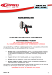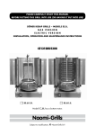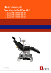
1
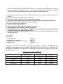
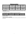
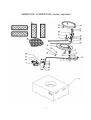
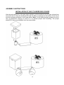
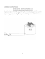
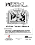
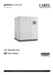
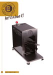
Happy Cocooning
COCOON TABLES
ASSEMBLY INSTRUCTIONS AND SAFETY GUIDE
U
10BU
SRRSO65xx/I2+ & SRRSO40xx/I2+ SERIES
SRS6510/I2+ & SRS4010/I2+
SRS6504/I2+ & SRS4004/I2+
SRR6501/I2+ & SRR4001/I2+
0063/11
SRRSO65xx/I2+ Σ QN= 19 kW, 1383 g/h I3+(28-30/37), I3 B/P(30), I3 B/P(50), I2L & I2H/I2E/I2E+
SRRSO40xx/I2+ Σ QN= 12 kW, 874 g/h I3+(28-30/37), I3 B/P(30) & I3 B/P(50) & I2L
SRRSO40xx/I2+ Σ QN= 13 kW, 747 g/h I2H/I2E/I2E+
BE, CY, CZ, EE, GR, IT, IE, PT, ES, LU, GB, FR, IS, LT, PT, SK, CH: Cat. I3+ Butane(G30)=28~30 mbar,
Propane(G31)=37 mbar, Injector-SRRSO65xx:2.2 mm SRRSO40xx:1.65mm.
CY, CZ, DK, EE, FI, GR, LV, LT, LU, MT, NL, NO, SK, SI, SE, TR, HU: Cat. I3 B/P(30)=Butane and Propane
mixtures at 30mbar, Injector-SRRSO65xx:2.2 mm SRRSO40xx:1.65mm.
AT, DE, SK, CH: Cat. I3 B/P(50)=Butane and Propane mixtures at 50mbar, Injector-SRRSO65xx:1.9mm
SRRSO40xx:1.45mm.
AT, BE, CH, CZ, DE, DK, EE, ES, FI, FR, GB, GR, HU, IE, IT, LT, LU, LV, NL, NO, PL, PT, RO, SE, SI, SK: Cat. I2L
Natural Gas(G25) at 25mbar, Injector- SRRSO65xxI2+: 4.1mm SRRSO40xxI2+: 3.0mm; I2H/I2ENatural Gas(G20)
at 20mbar, and I2E+ Natural Gas(G20) at 20mbar, Natural gas(G25) at 25mbar; Injector- SRRSO65xxI2+: 3.65mm
SRRSO40xxI2+: 3.0mm
“ Only nationally approved hose and regulator corresponding to the appliance category and pressure must be used ”
24B
This manual is for: AT, CH, DE
PIN NO.: 0063BT7387
25B
FOR OUTDOOR USE ONLY
26B
Read the instructions before using the appliance
32B
Warning: Accessible parts may be very hot, keep young children away.
1B
ASSEMBLY AND USER INSTRUCTIONS
11B
FOR
OUTDOOR GAS FIRE PITS
12B
USING LIQUEFIED PETROLEUM GAS
Your new Cocoon Table SRRSO65xx/I2+ & SRRSO40xx/I2+ is made from the highest quality
materials, and produced under strict manufacturing controls.
Please read the Instructions for assembly before commencing, and follow the instructions for
use carefully. We congratulate you on your decision to buy this outdoor gas grill and wish you
great fun when warming with it.
PLEASE READ THESE SAFETY INSTRUCTIONS
IN FULL BEFORE COMMENCING ASSEMBLY.
Important Safety instructions
The fire pit is safe and easy to use. The following rules must be followed.
1. Ensure that the unit has been assembled correctly according to the instructions.
2. Never loosen, or allow the gas connection to become loose. Should this happen, immediately
ensure that the gas is turned off, and then re-check the security of the connection.
3. The appliance shall be kept away from flammable materials.
4. Read the Users instruction, Sections, and instructions written on the fire pits, refer to them
whenever necessary.
5. Never leave the fire pit unattended while using.
6. In the event of a gas leak, turn off gas supply at the LPG cylinder or the main shut off valve
of city network gas.
7. Keep children well clear while fire pit is in use and after use until it has cooled.
8. Keep warming area clear of combustible materials and/or liquids.
9. Never obstruct free flow of air to the fire pit, or alter/adapt the fire pit to suit any other
situation.
10. SRRSO65xx & SRRSO40xx: A hose conforming to the national standard must be connected
at one end to the LPG regulator and at the other to the fire pit nipple using hose clips. The
hose length is 2.5m. For the hose exposed, please be sure to use (a) rubber/PVC layer(s) to
cover on it to prevent people from stumbling. The proper rubber/PVC layers are available
from the same dealer.
SRRSO65xxI2+ & SRRSO40xxI2+: A hose conforming to the national standard must be
connected at one end to the main shut off valve of city network gas and at the other to the
1
fire pit inlet with a national standard NG connector. For the hose exposed, please be sure to
use (a) rubber/PVC layer(s) to cover on it to prevent people from stumbling. The proper
rubber/PVC layers are available from the same dealer or qualified installer.
11. Lead the hose away from the fire pit without twisting it. Do not let the hose touch the hot
surface.
12. Never change the air valve settings of the burner.
13. Every time the gas connection is reconnected do a leak test.
14. That parts sealed by the manufacturer or the agent must not be altered by the user.
15. Any modification of this gas fire pit may be dangerous.
16. Do not move this fire pit during use.
17. Turn off the gas supply after use.
18. Do not touch the logs or lava rocks until they cool down.
19. This appliance is intended for warming purposes.
20. This appliance has a naked flame, a suitable guard should be used for the protection
of young children, the elderly and the infirm.
21. When first use, preheat the lava rocks for 15 minutes to burn out the impurities and air in the
natural lava rocks.
Contents
13B
1. Technical Data
2. Instructions for assembly
3. Installation and operation instructions
4. Maintenance
Page 2-3
Page 4-7
Page 8-11
Page12-16
14B
15B
16B
17B
18B
19B
20B
21B
The gas fire pits are I3+(28-30/37), I3 B/P(30) ,I3 B/P(50), I2L(G25) & I2H/I2E/I2E+(G20)
appliances, designed to operate on Butane at 28/30mbar, Propane 37mbar, B/P 30/50mbar, I2L
at 25mbar & I2H/I2E/I2E+ at 20mbar. Gas consumption, pressures and injectors orifices sizes
are shown below:
33BU
SRRSO65xx/I2+ GAS FIRE PITS
Injector Orifice
Heat Input(Hs)
34B
I3+(28-30/37), I3B/P(30)
2.2mm
37B
I3 B/P(50)
39B
1.9mm
19 kW
42B
I2L
43B
4.1mm
45B
I2H/I2E/I2E+
19 kW
38B
41B
49B
35B
19 kW
46B
47B
3.65mm
19 kW
50B
51B
2
36B
Gas Rate
1383 g/h
40B
1383 g/h
44B
2.1m3/h
48B
1.8m3/h
52B
53BU
SRRSO40xx/I2+ GAS FIRE PITS
Injector Orifice
Heat Input(Hs)
54B
I3+(28-30/37), I3B/P(30)
57B
I3 B/P(50)
61B
I2L
65B
I2H/I2E/I2E+
69B
55B
1.65mm
12 kW
58B
59B
1.45mm
12 kW
62B
63B
3.0mm
12 kW
66B
67B
3.0mm
13 kW
70B
71B
56B
Gas Rate
874 g/h
60B
874 g/h
64B
1.3m3/h
68B
1.2m3/h
72B
LP Gas Regulator
A gas regulator confirming to the national standard must be fitted to the gas cylinder to provide
the appropriate gas pressure.
The supply pressure of the LPG regulator must comply with the table blow:
I3B/P(30)
I3B/P(50)
I3+
LPG
LPG
Butane
Propane
28~30mbar
50mbar
28~30mbar
37mbar
Do Not use this appliance with an adjustable regulator. We suggest use this appliance with LP
gas cylinder of 10KG.
22B
2 Instructions for assembly
Read these instructions through carefully before commencing assembly, and then follow them
step-by-step.
23B
3
SRRSO65xx/I2+ & SRRSO40xx/I2+ series- parts list
No.
Description
Q’TY
No.
Description
Q’TY
01 Knob
1
21 Aluminum tube
1
02 Valve
1
22 Thermocouple
1
03 SS flexible tube
1
23 Pulse battery box
1
04 Injector fitting
1
24 Pipe clamp
1
05 Prop plank
1
25 Inlet fitting
1
06 Fix plank, Burner plate
3
26 Nut, Inlet fitting
1
07 Igniter needle
1
27 Igniter box
1
08 Burner plate
1
28 Lava rock,
1
09 Fix plank, Burner head, top
2
29 Log set
4
10 Pilot Igniter
1
30 Nut M8
6
11 Burner head
1
31 Screw M8F40
1
12 Fix plank, Burner head, bottom
1
32 Nut M6
2
13 Windpipe
1
33 Screw M5F20
6
14 Windscreen
1
34 Nut M5
6
15
3
35 Washer
4
16 Nut, Pilot Igniter
1
36 Screw M4F08
6
17 Washer
1
37 Control panel
1
18 Spring
1
38 Pit body
1
19 Support plank
1
39 Gas Inlet fitting
1
20 Contactor
1
Support tube, Burner plate, bottom
4.5KG, 6KG
Note: The part No. 39 is for SRRSO65xxI2+ and SRRSO40xxI2+ series only.
4
SRS6510/I2+ & SRS4010/I2+ series- exploded
5
SRS6504/I2+ & SRS4004/I2+ series- exploded
6
SRR6501/I2+ & SRR4001/I2+ series- exploded
27B
28B
29B
7
ASSEMBLY INSTRUCTIONS
U
GAS HOSE CONNECTIONS
Two adults will be needed, to assist each other with assembly.
SRRSO65xx & SRRSO40xx: Upraise the fire pit and attach the hose to the manifold inlet nipple
and tighten hose clip, or secure the hose to the manifold inlet fitting as shown in FIG.01 &
FIG.02 below.
SRRSO65xxI2+ & SRRSO40xxI2+: Upraise the fire pit and attach the hose to the manifold inlet
fitting with a national standard NG connector and secure the hose to the manifold inlet fitting as
shown in FIG.03 below. NOTE: Installation and service must be performed by a qualified
installer, service agency or your gas provider.
FIG.01
FIG.02
FIG.03
8
ASSEMBLY INSTRUCTIONS
U
INSTALLATION OF LAVA ROCKS AND LOGS
Unpack and put the lava rocks on ground. Pick up the solid lava rocks then layer them in level
across the burner plate. Bring it up to a level that is just over top of the burner by about 1”. Do
not completely cover burner element or block the igniter box with lava rock. Next, install the
imitation fire logs. These should be laid in as shown in the image below. Start by laying one log
in the centre of the unit. This log should be perpendicular to the igniter box and lay on top of the
centre support bracket. Lay the other logs, (quantity may vary by unit type), in a teepee
configuration over the first log. It is important that the logs not lay directly on top of the burner.
By blocking the burner it will impact air flow and will cause the unit to be difficult to ignite or will
impact how the flame comes through and burns. Once all the logs are in place as shown you
can begin next steps. NOTE: Be sure unit is cool before touching any of the components. NOTE:
When first use, preheat the lava rocks for 15 minutes to burn out the impurities and air in the
natural lava rocks.
9
30B
ASSEMBLY INSTRUCTIONS
INSTALLATION OF GAS CYLINDER ENCLOSURE
73BU
After the well connection to the gas supply cylinder, put the enclosure onto the gas cylinder then
cover with the lid. Align the hose pipe through the holes of passages at the bottom of the fire pit
and the enclosure as shown in the image below. Note: For the hose exposed, please be sure to
use (a) rubber/PVC layer(s) to cover on it to prevent people from stumbling. The proper
rubber/PVC layers are available from the same dealer.
10
31B
ASSEMBLY INSTRUCTIONS
74BU
INSTALLATION OF CITY NETWORK GAS
Upraise the fire pit and attach the manifold inlet fitting with the national standard NG connector
supplied. Connection of the NG supply to the appliance inlet should be made by a qualified
installer. Note: For the hose exposed, please be sure to use (a) rubber/PVC layer(s) to cover on
it to prevent people from stumbling. The proper rubber/PVC layers are available from the same
dealer or qualified installer.
11
NOTICE TO INSTALLER; THESE INSTRUCTIONS MUST BE CONVEYED TO AND REMAIN
WITH THE HOMEOWNER
Outdoor Gas Fire Pits
INSTALLATION AND OPERATION INSTRUCTIONS FOR OUTDOOR GAS FIRE PITS
WARNING: If the information in these instructions is not followed exactly, a fire or explosion may
result causing property damage, personal injury or loss of life.
Do not store or use gasoline or other flammable vapors and liquids in the vicinity of this or any
other appliance.
WHAT TO DO IF YOU CAN SMELL GAS FUMES:
Do not try to light any appliance.
Do not touch any electrical switches.
Do not use any phone, (including cellular phones)
Immediately call your gas supplier from a neighbor’s phone. Follow the gas supplier’s
instructions.
If you cannot reach your gas supplier, call the fire department.
Installation and service must be performed by a qualified installer, service agency or your gas
provider.
WARNING
WARNING: Improper installation, adjustment, alteration, service, or maintenance can cause
injury or property damage. Read the installation, operating and maintenance instructions
thoroughly before installing or servicing this equipment.
WARNING
WARNING: FOR OUTDOOR USE ONLY.
2B
WARNING
DO NOT LEAVE ANY OUTDOOR GAS APPLIANCE UNATTENDED WHEN IN USE OR
HOOKED UP TO A FUEL SUPPLY
3B
WARNING
DISCONNECT WHEN NOT IN USE AND KEEP OUT OF REACH OF CHILDREN
4B
GENERAL INFORMATION
WARNING
This appliance shall be used ONLY outdoors in a well- ventilated space and shall NOT be used
inside a building, garage, or any other enclosed area.
5B
WARNING
This appliance is not approved as a cooking device and should not be used as such.
6B
WARNING
THIS UNIT IS NOT FOR USE WITH SOLID FUELS.
7B
WARNING
Cylinders must be stored outdoors in a well-ventilated area out of reach of children.
Disconnected cylinders must not be stored in a building, garage or any other enclosed area.
8B
12
WARNING
Storage of this appliance indoors is permissible only if it has been disconnected from its fuel
supply
9B
Always keep the appliance area clear and free from combustible materials, gasoline, and other
flammable vapors and liquids.
Installation and repair should be done by a qualified service person. The appliance should be
inspected before use and at least annually by a qualified service person. More frequent
cleaning may be required as necessary. It is imperative the control compartment, burner and
circulation air passageways of the appliance be kept clean and free.
If it is evident there is excessive abrasion or wear of any of the components, if the fuel supply
hose is cut or cracked, it must be replaced prior to the appliance being put into operation.
Children and adults should be alerted to the hazards of high surface temperatures and
should stay away to avoid burns or clothing ignition.
Young children should be carefully supervised when they are in the area of the appliance.
Clothing or other flammable materials should not be hung from the appliance, or placed on or
near the appliance.
Any guard or other protective device removed for servicing the appliance must be replaced
prior to operating the appliance.
Inspect the fuel supply connection and all gas tubes for signs of leakage before each use of
the appliance.
The pressure regulator and hose assembly supplied with LP models must be used.
Replacement pressure regulator and hose assemblies must be those specified in this manual.
To connect the gas bottle to the unit:
Appropriate Regulators are available from the same dealers, for fitting to the hose supplied with
this unit.
.
Ensure that all connecting threads and surfaces are undamaged, clean and free
from oil dirt. When fitting the hose make sure that it is free from twisting, kinks or sharp bends.
Do not allow the hose to touch any hot surface or sharp edges.
2. Attach the regulator to the gas cylinder. Refer to the instructions supplied with the regulator
for details regarding fitting.
3. Test for gas leaks. Do a leak test each time the cylinder is installed, whether or not it has
been filled. Check all other joints and gas tubes at least once a year.
lf the hose shows deterioration or damage, leak test the entire outer surface, while under
pressure. Replace at first sign of leak or age cracking.
Remember to turn the cylinder valve OFF before removing the hose.
To connect the city network gas to the unit:
1. Attach the hose to the manifold inlet fitting with a national standard NG connector and secure
the hose to the manifold inlet fitting.
Ensure that all connecting threads and surfaces are undamaged and clean. When fitting the
13
hose make sure that it is free from twisting, kinks or sharp bends. Protect the hose from any
sharp edges.
2. Attach one end of the hose to the main shut off valve of city network gas.
3. Do a leak test each time when the gas connection is reconnected. lf the hose shows
deterioration or damage, leak test the entire outer surface.
Remember to turn the city network gas OFF before removing the hose.
Testing for Leaks
1. Ensure knob is OFF and open the cylinder valve.
2. Use a solution of half detergent and half water for leak testing. Brush
solution on each connection and check for bubbles.
3. lf a leak is present, turn off the gas supply and tighten the loose joint.
4. lf leak persists contact an authorized agent.
INSTALLATION
The gas cylinder enclosure, log set and crushed lava rock are shipped together on applicable
models. Remove the log set and un-pack all components. Check for damage caused by freight /
transport. DO NOT install damaged components. The logs are fragile use care when handling.
Place the fire pit on a level/secure surface in a desired location. The location must be adjacent
to the gas supply cylinder.
After the well connection to the gas supply cylinder, put the enclosure onto the gas cylinder then
cover with the lid.
NOTE: Minimum clearances: 1 meter to combustible construction must be maintained.
You must have clear and easy access to the on/off valve AFTER the appliance is installed and
connected to the gas supply in order to safely turn of the burner.
THE ON/OFF VALVE IS USED TO TURN THE BURNER ON AND OFF.
1. Cylinder should be positioned on a flat level surface near the fire pit, but within the predescribed safe distance 1 meter away.
2. Make sure the tank valve is in its full off position.
3. Never attempt to use damaged or plugged equipment. See your local LP Gas Dealer for
repairs.
4. Connect and tighten the end to the gas regulator with the clip.
5. When connecting regulator assembly to the tank valve, hand tighten it to a positive stop.
6. Locate the hose out of the pathways where people may trip over it or in areas where the
hose may be subjected to accidental damage.
7. Open tank valve fully. Turn the on/off valve at the unit to the ‘off’ position to pressurize the
hose assembly. Use a soapy water solution to check all the connections between the gas
tank connection and the ball valve at the back of the control panel for leaks before attempting
to light the appliance. If a leak is found, turn the tank valve off and do not use the appliance
until repairs can be made. Note that the unit must be turned upside-down to perform this
examination. It is also important to remove battery from igniter before performing any leak
testing by unscrewing the push-button knob at the control panel. Perform leak test in a well
ventilated area outside and where no source of spark can occur.
8. If everything is secure and leak free to this point you are ready to light your fire pit. Read
OPERATION instructions.
14
OPERATION
Upon completing the gas line connection, a small amount of air will be in the lines. When the first
lighting the burner, it will take a few seconds for the lines to purge themselves of this air.
Once the purging is complete, the burner will light and operate as indicated in the instruction
manual. Subsequent lighting of the appliance will not require such a purging unless the gas
supply has been disconnected.
WARNING: Read and follow the safety and lighting instruction page in this manual and on the
labels on the appliance.
BY NOT FOLLOWING INSTRUCTIONS, A FIRE/ EXPLOSION MAY RESULT. YOU MAY BE
SERIOUSLY INJURED.
BASIC SET UP
Once the fire pit is in position, level and safely hooked up to the proper fuel supply, it is now time
to install the crushed lava rock. This is also an essential part of the overall set-up as it will impact
the way the unit burns if not properly installed.
Layer the lava rock in level across the burner plate. Bring it up to a level that is just over top of
the burner by about 1”. Do not completely cover burner element or block the igniter box with lava
rock. Next, install the imitation fire logs. These should be laid in as shown in the image above.
Start by laying one log in the centre of the unit. This log should be perpendicular to the igniter
box and lay on top of the centre support bracket. Lay the other logs, (quantity may vary by unit
type), in a teepee configuration over the first log. It is important that the logs not lay directly on
top of the burner. By blocking the burner it will impact air flow and will cause the unit to be
difficult to ignite or will impact how the flame comes through and burns. Once all the logs are in
place as shown you can begin next steps. NOTE: Be sure unit is cool before touching any of the
components.
FOR YOUR SAFTY READ BEFORE LIGHTING
A. Before operating smell all around the appliance area for gas odors and next to the floor
because some gases are heavier then air and will settle on the floor.
B. Use only your hand to turn the manual gas control valve. Never use tools. If the valve will not
turn by hand, do not try to repair it. Call a qualified service technician. Force or attempted
repair may result in a fire or explosion,
C. Do not use this appliance if any part has been under water. Immediately call a qualified
service technician to water.
WHAT TO DO IF YOU SMELL GAS
Do not try to light any appliance.
Do not touch any electric switch; do not use any phone in your building.
Immediately call your gas supplier’ from a neighbors phone. Follow the gas supplier’s
instructions.
If you cannot reach your gas supplier, call the fire department.
LIGHTING INSTRUCTIONS
1. Remove protective storage cover and locate the manual gas control valve and igniter button
on the fire pit.
2. Make sure fuel supply is properly connected and turned on at the source / tank.
15
3. Depress igniter button until you hear it sparking. You will hear a small popping noise. If you
do not hear the igniter sparking you may need to replace the battery. Replace with a
standard AAA battery, directly behind the rubber push button knob, (unscrew knob to access
battery). Keep igniter button pushed in while pushing then turning the fuel flow valve to the
ON/Low flow position at the fire pit. The jet pilot fire should light the burner within 15 seconds;
after the burner lit, release the igniter button but still keep pushing the fuel flow valve for 20
seconds to allow the thermocouple to function. After the 20 seconds, release the fuel flow
valve; if the burner keeps lit, you can adjust the flame to HI. However, if the flame extincts
after the fuel flow valve released, Re-try or go to trouble-shooting and start from Step-1 again.
TO TURN OFF GAS
Turn the ON/OFF valve to the off position at the unit, then turn the valve on the LP tank, or the
main shut off valve of natural gas system, to the OFF position.
MAINTENANCE
1. The appliance should be inspected before initial use and inspected and cleaned at least
annually by a qualified service person.
2. Tampering is DANGEROUS and voids all warranties. Any component that is found to be
faulty, must be replaced with an approved component.
3. To obtain proper operation, it is imperative that the burner flame characteristics are constant,
not lifting or floating. For a clean burn the unit is designed to run at full flow. If not operating
at full fuel flow black smoke may start to occur. Always operate at full fuel flow to burn clean
and prevent smoke. Dirty logs can be easily cleaned off with water and light soap.
4. Periodically remove the logs and examine the burner and its components. If dirty, clean with
a soft brush and soapy water solution. Also examine the area around the burner. Any dirt or
foreign material, such as spider webs or nests in this area should be removed. This will
ensure long life, safe and trouble free operation.
5. Periodically check the hose connecting the LP gas cylinder to ensure it is not cracked or
damaged in any way.
NOTE: Carbon (soot) may built up on the surface of the logs over time or with extended use.
This is more likely to occur when using LP gas. The soot should be cleaned off the surfaces of
the imitation logs periodically to prevent excessive build up. To clean the logs, be sure the fire is
out, the gas supply is turned off and the logs are cool to the touch. The soot can then be
brushed of with a dry bristle brush or cloth. Take care while cleaning the logs as they can
become damaged if mishandled. Care should be taken to dispose of the soot and the cleaning
materials properly. Keep away from clothing and outdoor furniture.
During the cold winter months or in colder climates, it is recommended to disconnect the fire pit
and store it in a cool dry place. Do not store the LP gas tank inside. For the balance of the year,
protect and cover your fire pit from the rain, freezing rain or heavy snow by using the custom
cover than comes with the kit. Before installing the cover make sure the unit is shut off, that the
gas lines are disconnected and that the unit has had sufficient time to cool. Install the cover and
use the tie-down straps to secure it tightly to the unit to prevent the wind from blowing it off.
Produced on behalf of:
HAPPY COCOONING B.V.
Provinciënbaan 1
5121 DK Rijen
16
The Netherlands
Tel: +31 (0) 161 750270
Fax: +31 (0) 161 750375
17