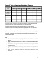
1
HDAVS IR Motorized Vari-focal Vandal-proof Dome Camera User’s Manual Version 1.0.1 Table of Contents 1 General Introduction .................................................................................................................. 6 1.1 Overview ........................................................................................................................ 6 1.2 Features ......................................................................................................................... 6 1.3 Functions ....................................................................................................................... 6 2 Framework and Dimensions ..................................................................................................... 8 3 Installation ................................................................................................................................... 9 4 Menu........................................................................................................................................... 12 4.1 HDAVS Series DVR Settings ................................................................................... 12 4.2 Note .............................................................................................................................. 13 Appendix Toxic or Hazardous Materials or Elements ............................................................... 14 Welcome 1 Thank you for purchasing our HDAVS camera! This user’s manual is designed to be a reference tool for your system. Please read the following safeguard and warnings carefully before you use this series product! Please keep this user’s manual well for future reference! Important Safeguards and Warnings 1.Electrical safety 2 All installation and operation here should conform to your local electrical safety codes. The power shall conform to the requirement in the SELV (Safety Extra Low Voltage) and the Limited power source is rated 12V DC in the IEC60950-1. We assume no liability or responsibility for all the fires or electrical shock caused by improper handling or installation. 2.Transportation security Heavy stress, violent vibration or water splash are not allowed during transportation, storage and installation. 3.Installation Do not apply power to the camera before completing installation. Please install the proper power cut-off device during the installation connection. Always follow the instruction guide the manufacturer recommended. If this product is installed in the ceiling, please make sure the installation position can sustain the min 50N. 4.Qualified engineers needed All the examination and repair work should be done by the qualified service engineers. We are not liable for any problems caused by unauthorized modifications or attempted repair. 5.Environment This series HDAVS camera should be installed in a cool, dry place away from direct sunlight or strong light, inflammable, explosive substances and etc. This series camera shall work on the specified working temperature. Please keep it away from the electromagnetic radiation object and environment. Please make sure the CMOS component is out of the radiation of the laser beam device. Otherwise it may result in CMOS optical component damage. Please keep the sound ventilation. Do not allow the water and other liquid falling into the camera. 6. Accessories Be sure to use all the accessories recommended by manufacturer. Before installation, please open the package and check all the components are included. Contact your local retailer ASAP if something is broken in your package. 7. Daily Maintenance Please shut down the device and then unplug the power cable before you begin daily maintenance work. Use the dry soft cloth to clean the device. If there is too much dust, please use the water to dilute the mild detergent first and then use it to clean the device. Finally use the dry cloth to clean the device. 3 Please put the dustproof cap to protect the CMOS component when you do not use the camera. 4 Applicable model This manual can be applied to following model: AVS-D2218Z 5 1 General Introduction 1.1 Overview This series megapixel HD camera conforms to the HDAVS standard. It supports video signal high-speed long distance transmission without any delay. It can be controlled by the DVR conforming to the HDAVS. 1.2 Features High-performance CMOS image sensor, megapixel definition. Default motorized vari-focal lens, adopt auto focus technology, support coaxial cable to control lens zoom and focus. Support HD video and control signal coaxial transmission. Support 75-3 coaxial cable transmission without any loss. 720P series transmission distance over 500m, 1080P series transmission distance over 300m. High speed, long distance real-time transmission. Support HDAVS HD and analog SD switch output. 720P series support 720P@25, 720P@30, 720P@50, 720P@60. 1080P series support 1080P@25, 1080P@30, 720P@25, 720P@30, 720P@50, 720P@60. Support high performance 3D noise reduction (denoise), excellent performance in low illumination Support ICR switch to realize surveillance both in the daytime and at night. Support OSD (on-screen display), suitable for user self-defined setup. Support DC12V power supplying. IP66, IK10 compliance. Support intelligent IR function, max IR distance 30m. 1.3 Functions HDAVS Specification HDAVS(High Definition Composite Video Interface) is an over-coaxial –cable HD video transmission standard. The technology renders two HD video formats by progressive scanning. Auto Focus Technology Detect the location of main screen by the camera auto focus algorithm, and auto adjust focus motor according to the current focus situation, which would realize zoom control the entire auto focus. The image stays clear during the process of zooming. OSD User-friendly on-screen display for you to select the different functions. ICR The IR cut removal is to filter the IR light in the daytime and then auto switch to the general fitter at night. This function allows the camera to output the high sensitivity and clear video. 6 Smart IR technology The sensor controls the IR light on/off via the combination work of the hardware and software, which realizes the automatically IR light compensation according to the environment illumination. 3D NR Comparing with the general 2D denoise function, the 3D denoise function can not only denoise the brightness of the video separation signal and saturation signal, it can also denoise the original data from CCD. It greatly enhances noise reduction performance and guarantees clear and bright video. 7 2 Framework and Dimensions Please refer to the following figures for dimension information. The unit is mm. See Figure 2-1 to Figure 2-3. Figure 2-1 Figure 2-2 When the standard definition/high definition switch control cable is short circuit, system outputs standard definition video. Otherwise, when the circuit is open, system outputs the high definition video. Figure 2-3 8 3 Installation Important Before the installation, please make sure the installation surface can sustain at least 3X weight of the bracket and the camera. The dome camera usually uses the ceiling installation. It can be installed on the ceiling or the wall. Please refer to Figure 3-1 for installation hole site. For side exit cable installation, please make sure the side exit cable direction is the same as shown in the installation position map. Before you secure the screws on the pedestal, please put the cable through the cable exit of the pedestal. Before you complete the installation and debug, do not remove the electrostatic film. After you remove the film, do not touch the enclosure in case there is any scratch. Figure 3-1 9 Figure 3-2 Step 1 Take the installation position map from the accessories bag and then put it on the surface of the ceiling or the wall according to the cable exit position. Dig three holes according to the installation position map and then take three expansion bolts from the accessories bag and put them to the holes you just dug. Step 2 Use inner hex wrench to remove the three case locking screws and then remove the dome enclosure. Step 3 Adjust the pedestal position according to the cable exit mode (ceiling/side). Pull the cable through the cable side exit at the installation surface and the pedestal (Please skip this step if you want to use ceiling exit mode). Line up the screw holes at the bottom of the pedestal to the expansion bolts in the installation surface. Put three self-tapping screws to expansion bolts and then secure firmly. Now the pedestal is on the installation surface. Step 4 Connect the video output port of the device cable to the HDAVS DVR, and connect the power port of the device cable to the power. After the image is shown on the HDAVS DVR, control the interface by HDAVS series DVR PTZ, adjust lens zoom by using coaxial control, and the camera will auto focus to the best position. 10 Step 5 Use three case locking screws to secure the dome housing on the pedestal. Now you have completed the device installation and cable connection. , You can use the terminal encode devices to view the monitor video. 11 4 Menu 4.1 HDAVS Series DVR Settings Note The following operation and interfaces for reference only. Please refer to the HDAVS series DVR user’s manual for detailed information. After connected the camera to the HDAVS series DVR, from Main Menu->Setting->System>PTZ, you need to set control mode as HDAVS and the protocol as DH-SD1. Click Save button to save current setup. See Figure 4-1. Figure 4-1 On the preview interface, right click mouse and then select PTZ; you can see an interface shown as below. See Figure 4-2. Figure 4-2 Click Iris “+” to open menu or confirm current operation. 12 Click Iris “-” to realize auto focus. Click up/down button to view all the items on the left pane of the following list. Click left/right button to set the corresponding values on the right pane of the following list. If there is “ ”, click confirm button to go to the 2nd menu. Repeat the previous steps to set detailed value. Click Return button to go back to the previous menu interface. Click Zoom “+” to zoom in and click Zoom “-” to zoom out. 4.2 Note Parameter Function Brightness It is to adjust monitor window bright. The value ranges from 0 to 100. The default value is 50. The larger the number is, the bright the video is. When you input the value here, the bright section and the dark section of the video will be adjusted accordingly. You can use this function when the whole video is too dark or too bright. Please note the video may become hazy if the value is too high. The recommended value ranges from 40 to 60. Contrast It is to adjust monitor window contrast. The value ranges from 0 to 100. The default value is 50. The larger the number is, the higher the contrast is. You can use this function when the whole video bright is OK but the contrast is not proper. Please note the video may become hazy if the value is too low. If this value is too high, the dark section may lack brightness while the bright section may over exposure .The recommended value ranges from 40 to 60. Saturation It is to adjust monitor window saturation. The value ranges from 0 to 100. The default value is 50. The larger the number, the strong the color is. This value has no effect on the general brightness of the whole video. The video color may become too strong if the value is too high. For the grey part of the video, the distortion may occur if the white balance is not accurate. Please note the video may not be attractive if the value is too low. The recommended value ranges from 40 to 60. Sharpness The value here is to adjust the edge of the video. The value ranges from 0 to 100. The larger the value is, the clear the edge is and vice versa. Please note there is noise if the value here is too high. The default value is 50 and the recommended value ranges from 40 to 60. 3DNR It is to reduce video noise. The larger the number is, the lower the noise is. The details of the video may disappear if the value here is too large. Anti-flicker Outdoor: In this mode, you can switch exposure mode to get the effect under the corresponding exposure mode. 50Hz: When the current is 50Hz, system can auto adjust the exposure according to the environment brightness in case there is any strip. 60Hz: When the current is 60Hz, system can auto adjust the exposure according to the environment brightness in case there is any strip. 13 Appendix Toxic or Hazardous Materials or Elements Toxic or Hazardous Materials or Elements Component Name Pb Hg Cd Cr VI PBB PBDE Circuit Board Component ○ ○ ○ ○ ○ ○ Device Construction Material ○ ○ ○ ○ ○ ○ Wire and Cable ○ ○ ○ ○ ○ ○ Packing Components Accessories ○ ○ ○ ○ ○ ○ ○ ○ ○ ○ ○ ○ O: Indicates that the concentration of the hazardous substance in all homogeneous materials in the parts is below the relevant threshold of the SJ/T11363-2006 standard. X: Indicates that the concentration of the hazardous substance of at least one of all homogeneous materials in the parts is above the relevant threshold of the SJ/T11363-2006 standard. During the environmental-friendly use period (EFUP) period, the toxic or hazardous substance or elements contained in products will not leak or mutate so that the use of these (substances or elements) will not result in any severe environmental pollution, any bodily injury or damage to any assets. The consumer is not authorized to process such kind of substances or elements, please return to the corresponding local authorities to process according to your local government statutes. Note This manual is for reference only. Slight difference may be found in the user interface. All the designs and software here are subject to change without prior written notice. All trademarks and registered trademarks mentioned are the properties of their respective owners. If there is any uncertainty or controversy, please refer to the final explanation of us. Please visit our website or contact your local service engineer for more information. 14