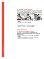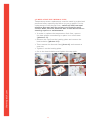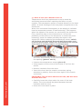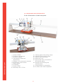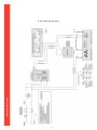
1
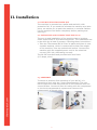
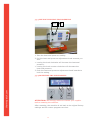
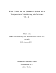
thermopatch.com
NL-26 User manual
Mar 2013
ENG
Copyrights
© 2012, Thermopatch bv, Almere, The Netherlands. No part of
this publication may be reproduced by any means without the
prior written permission of Thermopatch bv, The Netherlands.
thermopatch.com
Thermopatch and the Thermopatch logo, Thermoseal and
Thermocrest are registered trademarks of Thermopatch.
2
Preface
Congratulations and welcome to the ever growing number of
Thermopatch users.You have acquired a machine which has
been manufactured by Thermopatch with the greatest possible
care. We are confident that you will be enjoying the use of this
machine for a long time.
Please take note of the contents of this manual to familiarize
you with the workings and safety aspects of the machine.
This manual was written for the benefit of all users and
technicians who install and maintain the machine.
thermopatch.com
You will find information on operating, safety and maintenance
as well as spare parts and supplies.
3
Table of Contents
Preface
3
EC-Declaration of Conformity
5
I. Introduction
6
1.1
What did you receive?
6
1.2
Your supplier
6
1.3
Specifications of the Thermoseal NL-26
6
1.4
Safety
8
1.5
Conditions of warranty and product liability
8
II. Installation
9
2.1
Instruction for handling
9
2.2
Installing and connecting the NL-26
9
2.3
Assembly
9
III. Operating the NL-26
thermopatch.com
VI. 10
3.1Starting up
10
3.2Functionality
10
3.3 Safety
10
3.4 The Display and operating panel
12
3.5 Settings
13
3.5.1 TEMPERATURE AND TIME
13
3.5.2 Other settings
14
3.5.3 HEAT SEAL MACHINEURE
17
3.5.4 RESETTING THE ELECTRONICS
17
3.6 ERROR MESSAGES
18
3.7 TURNING THE HEATING PLATE
19
3.8 RAISING AND LOWERING THE HEATING PLATE
19
Maintenance
20
4.1 DAILY MAINTENANCE
20
4.2 REPLACING THE FUSES
21
4.3 REPLACING THE MAIN FUSE
21
4.4 REPLACING THE POWER SUPPLY
22
4.5 REPLACE THE FUSE IN THE POWER SUPPLY
23
4.6 REPLACING THE ELECTRONICS
24
4.7 REPLACING THE OPERATING PANEL
24
4.8 REPLACING THE THERMAL FUSE
25
4.9 REPLACING THE THERMO COUPLE
26
4.9.1 TROUBLESHOOTING TABLE
4.10 DIAGRAMS AND SCHEMATICS
27
28
4.10.1 ILLUSTRATION OF THE HEAT PRESS
28
4.10.2 WIRING DIAGRAM
29
4.10.3 PNEUMATICS DIAGRAM
30
4
EC-Declaration of Conformity
We,
Thermopatch B.V.
Draaibrugweg 14
1332 Almere
The Netherlands
Herewith declare, on our own responsibility, that the
machinery: Thermopatch Thermoseal NL-26, which this
declaration refers to, is in accordance with the conditions
of the following Directive(s):
2006/42/EG 2004/108/EG (Machinery directive)
(EMC directive)
The Netherlands, Almere, 01-01-2013
thermopatch.com
Jan Bausch,
Director
5
I. Introduction
1.1 What did you receive?
The Thermoseal NL-26 is supplied in two seperate items, a
bridge and a press head, mounted on a pallet. The following
items are included:
• Thermoseal NL-26 heatsealmachine
• Power cord
• 6 mm air tubing
• CD with manual
• CE declaration of conformity
If one or more of above are missing, please contact your
Thermopatch supplier.
1.2 Your supplier
Please look at our website to find your supplier,
www.thermopatch.com.
E-mail: [email protected]
1.3 Specifications of the Thermoseal NL-26
The pneumatic machine NL-26 is practical and universally
applicable. It can be used to apply patches, textile emblems,
heat seal transfers, in short all Thermopatch heat seal products
for marking and mending of textiles and technical fibres.
thermopatch.com
The Thermoseal NL-26 has been manufactured in accordance
with the European guideline for Machines, 2006/40/EC and the
EMC guideline 2004/108/EC. This is declared with a general
declaration of conformity (CE declaration) added to this manual
and uniquely serial number based to this machine.
6
Specifications
Power consumption
1000 Watt/230 Volt
Power supply
230 Volt
Temperature adjustable to maximal
0 – 230°C
Safety temperature set to maximal
270°C
Height
63 cm
Width
181 cm
Depth
63 cm
Nett weight press head
20 kg
Nett weight of the guideway
115 kg
Sealing pad, size
220 x 320 mm
Fuses
1 x 10A
A-weighted noise level
< 70 dB (A)
Pre-pressure
6 bar
Sealing pressure
4-6 bar
Safety settings (max)
6 bar
Compressed air usage (per cycle)
± 0.7 litre
Sealing times, adjustable from – to
1 – 60 minutes
Attention!
thermopatch.com
To obtain the required sealing pressure, the NL-26 has to be connected to a
compressor with a working pressure of 6 bars. The air has to be clean and dry.
7
1.4 Safety
At normal usage, no problems are to be expected. Regardless
that, we state underneath a few points of advice, which will
limit existing risks to a minimum.
Operation of the machine has to be performed by trained
personnel only. Please ensure that all trained personnel have
familiarized themselves with the contents of this manual.
• Unplug the machine from the wall socket whenever you are
maintaining or cleaning the machine.
• Make sure there is enough working space around the
machine. Although the heat radiation of the heat seal
machine is very low, it is still necessary to have enough
room for cooling down. Extensions and connections must
not get snagged.
• Ensure enough space around the machine to perform
the operation without any hindrance from surrounding
activities.
• Take care to avoid contact with the press arm and the
heating element.
• Pull the fabric tightly over the worktop.
During heat sealing activities strong smelling vapours can
be released from the textile. Thermopatch advises to ensure
that proper ventilation is available on the workplace.
1.5 Conditions of warranty and product liability
thermopatch.com
Thermopatch points to its warranty and product liability
conditions as laid down in our sales conditions. These are
available at your Thermopatch supplier.
8
II. Installation
2.1 Instruction for handling
The machine is mounted on a pallet and sealed in with
protective foil. If you need the relocate the machine at a later
point, we advise you to pack the machine in a similar fashion.
Let the machine cool down completely before packing and
moving it.
2.2 Installing and connecting the NL-26
The set-up and installation of the machine has to be done
under supervision of an authorized person. The installation has
to be done by at least 2 persons, following these instructions:
•Take the Thermoseal NL-26 from its pallet and place it onto
a stable worktop, which is constructed to bear the weight
of the machine, near an earthed wall socket. Connect the
machine with the supplied power cord to the electrical
current (230 Volt, alternating current).
The NL-26 is earthed and provided with two fuses
(6.3 Amps, slow).
2.3 Assembly
thermopatch.com
To ensure a problem-free operating of your NL-26, it is
essential to work with dry, clean compressed air. The user
has to make sure that the pressure on the machine does not
exceed 6 Bars. Connect 6 bars air tubing with the compressor
or the local compressed air system and connect this
subsequently to the air inlet.
9
III. Operating the NL-26
3.1 Starting up
After a correct installation of the heat seal machine, it is
important to ensure that it works properly, has not been
damaged and has no safety defects.
•If any damages or defects are found, contact your supplier
immediately.
You can start operating the NL-26 as soon as it is connected
to the electricity mains.
• Set the air pressure.
•Take note of the conditions and working instructions as
stated in chapter 2.
•Switch on the NL-26 by heat sealing the green on–off
(I-0) switch, which is placed on the right hand side of the
machine, to “on (I)”.
• Wait until the set temperature has been reached.
3.2 Functionality
Before the first start up make sure that the power outlet is in
the right condition and that the grounding is connected to the
power outlet. Connect the machine to the compressed air, the
pressure must not exceed 6 bar. The machine also has to be
open while heating up. The machine can be turned on with the
green on-off switch (7). If the green switch glows the machine
heats up to the adjusted temperature.
Start the machine with the both green buttons START. The heat
platen lowers itself down and presses against the lower platen.
After the heat sealing process finishes, the machine opens
automatically. When the machine is not used, switch it off and
unplug the power cord from the wall socket.
3.3 Safety
The NL-26 heat seal machine is equipped with different safety
features, to warrant a safe usage.
thermopatch.com
Main fuse 10A
The main fuse 10A is placed on the back of the machine.
In case of overcharge, the main fuse prevents the heat
machine from getting damaged.
Once the fuse was activated, it has to be replaced. The
instruction for replacing the main fuse can be found in
chapter 4.4.
10
Fuse 1,6A
This fuse is placed in the 12VAC power supply in the upper
part of the heat machine. It saves the 12VAC circuit of an
overcharge. Once the fuse was activated, it has to be replaced.
The instruction for the exchange you can see in chapter 4.6.
Thermal fuse
The thermal fuse is placed directly on the heating plate and
it stops the power supply if the temperature exceeds 260°C.
If this fuse is activated, the temperature sinks down to 90°C.
After that the power supply gets activated again and the
temperature of the heating plate rises and you can work with
the machine again. Certainly you need to install a new thermal
fuse within the next days. The instruction for the replacement
of the thermal fuse can be found in chapter 4.9.
Safety valve
In the pressure pipe inside the machine a safety valve is
fitted which is automatically activated when the pressure
exceeds 6 bar.
Automatic switch-off
If the heat seal machine is not opened within 10 seconds
after the heat sealing cycle, the heating element switches off
automatically, to prevent the risk of burning or fire.
Bi-manual control
Both green push bottons need to be heat seal machined
simultaneously in order to start the sealing cycle.
Emergency stop button
An emergency stop button is fitted to shut down the machine
immediately after activation.
Touch bar
thermopatch.com
The heat seal machine head is provided with a safety touch bar
which shuts the machine down when it is touched or meets an
obstruction during the heat sealing cycle.
11
3.4 The Display and operating panel
1
2
3
5
4
1. Current temperature of the heating plate
2.Energy consumption
3.Indicator sign heating plate
4. Program number
5.Sealing time
thermopatch.com
setup
12
3.5 Settings
3.5.1 TEMPERATURE AND TIME
1. Push button ‘setup’ for 5 seconds. The display will show:
Temperature.
2.Set the required temperature by pushing the + or –
button on the operating panel.
3. Push the ‘setup’ button again.
The display will show: Timer
thermopatch.com
4.Set the heat sealing time by pushing the + or – button
on the operating panel.
5. Push the ‘setup’ button again.
13
3.5.2 Other settings
The display shows: Counter
6. With the + or – buttons on the operating panel you can
switch the counter On/Off.
7. After switching on the counter it counts the number of
heat sealing cycles.
•
To end the programming, push the ‘setup’ button.
•
To get to the advanced programming menu, press the
‘setup’ button for 3 seconds.
The display shows: Contrast
8.Set the contrast by pushing the + or – button on the
operating panel.
thermopatch.com
9. Press the ‘setup’ button.
The display shows: Brightness
10.Set the brightness by pushing the + or – button on the operating panel.
11.Press the ‘setup’ button.
14
The displays shows: Temp. view is/should be
The screen states the settings for temperature information.
12.By adjusting the settings with the + or – button you can
choose between the actual or the adjusted temperature to
be shown on the display.
13.Press the ‘setup’ button.
The display shows: Sound
14.Switch off or on by pushing the + or – buttons.
15.Press the ‘setup’ button.
The display shows: Counter (overall counter)
thermopatch.com
The screen states the total number of heat seal cycles.
16.Press the ‘setup’ button.
15
The displays shows: Labor time
The screen states the number of hours machine has been
operating.
17.Press the ‘setup’ button.
The display shows: Damage
In this screen you can check the electric circuits of the:
• Temperature fuse
• Thermo couple
• Power relay
thermopatch.com
18.To end the programming, push the ‘setup’ button.
16
3.5.3 SETTING THE HEAT SEAL PRESSURE
2+3
1
1.Take the heat seal pressure reading.
2.Pull the heat seal pressure adjustment knob towards you
and:
• turning the knob clockwise will increase the heat seal
pressure,
• turning the knob counter clockwise will decrease the
heat seal pressure.
3.Push the heat seal pressure adjustment knob inwards to
lock the setting.
thermopatch.com
3.5.4 Resetting the electronics
ATTENTION: We strongly advise to contact your supplier
before resetting the machine.
After resetting, the machine is set back to its original factory
settings and all custom programs are lost.
17
Resetting:
• Heat seal machine ‘setup’.
• Heat seal machine ‘–’ one second later.
• Hold both buttons for 20 seconds.
• Confirm the reset by touching the ‘–’ button or cancel it by
touching the ‘+’ button.
• Heat seal machine YES (‘–’) for confirming resetting to the
original setting.
3.6 Error messages
ERR.1 –No connection of the electronic devices to the
temperature sensor (Temperature sensor
defect/cable not connected).
ERR.2 – Connection of electronic devices and temperature
sensor bypassed (Temperature sensor defect).
ERR.3 – Resistor of temperature sensor too low.
The temperature range of the electronic devices
deceeded.
ERR.4 – Resistor of temperature sensor too high.
The temperature range of the electronic devices
exceeded.
ERR.5 – No temperature rise within 3 minutes even if
heating element switched on (Temperature fuse
defect).
ERR.6 – No reduction of the temperature within 3 minutes
even if heating element is turned off (Power relay
CRYDOM defect).
ERR.7 – Temperature too high, over 230°C (Power relay
CRYDOM defect).
thermopatch.com
ERR.3 and ERR.4 can occur if the machine was not
programmed properly.
18
3.7 Turning the heating plate
The heating plate of the NL-26 heat seal machine can be
turned into any desired position by turning it up to 90° using
the handle.
3.8 Raising and lowering the heating plate
The speed with which the heating plate is lifting and lowering
itself can be adjusted with the valve which is mounted on the
back of the NL-26.
When required, the settings can be changed by turning the
turning knob.
• Turn clockwise to increase the speed of lowering and lifting.
• Turn counter clockwise to decrease the speed of lowering
and lifting.
thermopatch.com
CAUTION!
When the speed is set too high, repositioning of the
transfers can occur when the heating plate comes down.
19
IV. Maintenance
4.1 Daily Maintenance
Before starting, make sure that the surface of the heating plate
and the worktop are clean. The heating plate can be cleaned
with a clean, dry cloth.
• Avoid contact with the heating plate to prevent the
risk of burns.
The worktop can be cleaned with a soft cloth and if
necessary, a mild household detergent can be used.
• Avoid scrub sponges, aggressive cleaners and solvents,
these will damage the surface of the machine.
Check the air filter, which is located at the back of the
machine, regularly and remove its contents if necessary.
It is not required to take the pressure off the machine to
perform this maintenance.
• Turn the plug located under the container (photos 1 – 2).
• If there is water left in the container, disconnect the
compressed air mains, remove the container by turning
it around (photo 3 – 4) and pour out its content.
• If necessary, clean the filter in the container. Undo and
remove the container, unscrew the bolt holding the filter
(photo 5).
thermopatch.com
• Take out the filter, clean it and screw it back in place.
20
4.2 Replacing the fuses
Ensure that the machine is disconnected from the electrical
power and the power cord is unplugged from the wall socket.
Replace the fuses on the back of the machine at the power
entry.
Before re-connecting the power cable into the wall socket,
make sure the net entry shows the right tension setting
(230 V or 110 V). If the wrong setting is shown, remove the
fuses and turn the fuse holder 180°. After replacing the fuses,
the machine can be connected and switched on again.
ATTENTION: Ensure that the right tension setting is visible,
before switching on the machine again!
4.3 Replacing the main fuse
If the heat seal machine does not work after it is switched
on (the main switch is glowing, but the display is not), check
the main fuse of the heat seal machine. The main fuse 10A is
placed on the back of the heat seal machine.
• To exchange the fuse, switch off the heat seal machine
first and pull the power cord from the wall socket.
• Screw the fuse bracket loose.
• Then remove the fuse bracket.
thermopatch.com
• Exchange the fuse and tighten the fuse bracket again.
21
4.4 Replacing the power supply
The heat seal machine is equipped with a main fuse
1,6A/12 Volt, which is placed in the head of the heat seal
machine. In the power supply is an indicator LED.
• When the LED glows, it indicates that the power supply
works.
• If the LED does not glow, the fuse 1,6A in the power
supply has to be exchanged.
To exchange the power supply, switch off the heat seal
machine first and pull the power cord from the wall
socket.
• Remove the cover of the machine (photo’s 1 and 2).
• Pull the green plug (photo 3).
• Remove the stopper of the power supply (photo 4).
• Replace the power supply (photo 5).
• Connect the green plug, fasten the power supply in the
upper part of the machine.
thermopatch.com
Reassemble the machine.
22
4.5 Replace the fuse in the power supply
The heat seal machine is equipped with a main fuse
1,6A/12 Volt, which is placed in the head of the heat seal
machine. In the power supply is an indicator LED.
• When the LED glows, it indicates that the power supply
works.
• If the LED does not glow, the fuse 1,6A in the power
supply has to be exchanged.
To exchange the power supply, switch off the heat seal
machine first and pull the power cord from the wall
socket.
• Remove the cover of the machine (see 4.4, photos 1
and 2).
• Screw loose the fuse bracket (photo 1).
• Exchange the fuse (photos 2 and 3).
thermopatch.com
Reassemble the machine.
23
4.6 Replacing the electronics
Inside the upper part of the machine, the electronics are fitted
which control the temperature and time settings. To exchange
the electronics, switch off the heat seal machine first and
pull the power cord from the wall socket.
• Remove the cover of the machine (see 4.4, photos 1
and 2).
• Pull out the green plug (photo 1).
• Pull out the temperature and time adjustment (photo 2).
• Loosen the stopper of the electronic devices.
• Remove the electronic devices (photo 3).
• Connect the new electronic devices and fit them into
the machine.
Reassemble the machine.
4.7 Replacing the operating panel
thermopatch.com
To change the electronics keyboard switch off the
heat seal machine first and pull the power cord from
the wall socket.
• Remove the cover of the machine (see 4.4, photos 1
and 2).
• Disconnect the keyboard plug from the electronics.
• Remove the keyboard from the press.
• Install a new keyboard and plug it into the electronics.
Reassemble the machine.
24
4.8 Replacing the thermal fuse
Temperature sensor replacement must be made by authorised
personnel after reporting the failure to your supplier. For the
replacement of the thermal fuse, switch off the heat seal
machine first and pull the power cord from the wall
socket. Make sure the machine has cooled down before
starting repairs or maintenance.
• In order to replace the temperature limit fuse, remove
the heat platen remembering to place it on a soft base
(photos 1-3).
• Remove the cap from the heating plate and remove the
heat isolation (photos 4-5).
• Then remove the thermal fuse (photo 6) and connect a
new one.
• Tighten it on the heating plate.
thermopatch.com
• Put in the heat isolation and tighten the cap again.
25
4.9 Replacing the thermo couple
Temperature limit fuse replacement must be made by
authorised personnel after reporting the failure to your
supplier. The temperature sensor is located directly on the heat
platen. It sends readings of the heat platen temperature to the
electronics.
When four horinzontal lines appear on the display it indicates
that the temperature sensor is malfunctioning. This happens
when the signals of the sensor are received by the electronics.
First, check the plug on the electronics to rule out the
possibility of the wires on the electronics or inside the press
loosening; check the cables providing the signal to the
electronics. Before replacing the temperature sensor, switch
off the heat seal machine first and pull the power cord
from the wall socket. Make sure the machine has cooled
down before starting repairs or maintenance.
• Unscrew the cover on the right of the heat platen, remove
the cover and carefully remove the thermal insulation from
the opening (photo 1 and 2).
• Unscrew the temperature sensor (photo 3).
• Using nippers cut the wires of the sensor 2 cm from the
sensor.
• Remove insulation from the wires.
• Insert the wires into the ceramic connectors paying
attention to polarity. Screw the wires tight in the ceramic
connectors.
thermopatch.com
CAUTION!!! The red wire with the red one, the blue wire
with the blue one.
• Carefully insert the wires under the cover of the heat
platen. The wires should be placed between thermal
insulation and the cover.
• Screw the cover back in place.
26
4.9.1 Troubleshooting table
Problem
• The main switchs glows, but
the display doesn’t
• The heating plate isn’t
heating up
Debugging
• Main fuse 10 A is defective If • Replace main fuse 10 A
the main fuse is okay, check
Replace fuse 1,6A in the
if the diode in the power
power supply or replace the
supply is glowing. If not the
power supply
fuse or the power supply is
defective
• If the diode is glowing the
• Replace the electronic
electronic devices are
devices
defective
• The display shows ”Err.5”
• Thermal fuse on the
heating plate is defective
• The display shows ”Err.1”
• Thermo couple is defective
• Check the cables to the
or the cables to the thermo
thermo couple or exchange
couple are defective
the thermo couple
• No connection to the heating • Put the plug of the heating
plate
plat into the socket
• The display shows ”Err.2”
•The thermo couple defective
Exchange the thermo couple
• The display shows ”Err.3”
• Resistance of the thermo
couple is too low
• Resistance of the thermo
couple is too high
• Exchange the thermo couple
• The display shows ”Err.6”
• The display shows ”Err.7”
• Power relay CRYDOM is
defective
• Replace power relay
CRYDOM
• Adjustment buttons aren’t
working
• No time or temperature
adjustments are possible
• Terature and time
adjustment areisfect
• Replace the temperature
and time adjustment
• Temperature of the heating
plate doesn’t correspond
to the Temperature on the
display – Temperature too
high/low
• Malfunction of the
electronic devices
• Reset the electronic devices
• The press heats up very
slowly – over 30 minutes
one half of the plate
doesn’t reach the adjusted
temperature
• The heating elements is
defective
• Replace the heating plate
and/or send it in for repairs
• The press will not stay down
• The time is not activated
• Micro switch is defective the
• Material is to thick and
so the micro switch isn’t
activated
• Mikroschalter einstellen oder
• Mikroschalter austauschen
• The press will not close
• Emergency button is
pressed down
• Compressed air is not
connected
• Pull the emergency
button out
• Connect the compressed air
• The display shows ”Err.4”
thermopatch.com
Cause
• The press will not open
•Pneumatic valve is defective
• The press will only open with
the emergency button
27
• Replace the thermal fuse
• Replace the pneumatic valve
4.10 Diagrams and schematics
4.10.1 Illustration of the heat press
thermopatch.com
1.
2.
3.
4.
5.
6.
7.
8.
9.
10.
Switch START
Pressure Adjustment
Pressure gauge
T
emperature and time
adjustment
Display of the electronic devices
Emergency push-button
Main switch
Guideway
Switch STOP
Worktop 180 x 32 cm
11.
12.
13.
14.
15.
Heating plate with safety frame
Handle of the heating plate
Power cable with plug
Main fuse 10A
Spiral tube with connection to
the heating plate
16. Raising and lowering the
heating plate
17. Compressed air connection
18. Air filter with water separator
28
thermopatch.com
4.10.2 Wiring diagram
29
thermopatch.com
4.10.3 Pneumatics diagram
30
thermopatch.com
Thermopatch Corporate Headquarters Thermopatch European Headquarters Thermopatch Australia Pty Ltd Thermopatch Canada Inc Kannegiesser UK Ltd. USA The Netherlands Australia Canada United Kingdom T
T
T
T
T
+1 315 446-8110 F
+31 36 549 11 11 F
+61 395325722 F
+1 519 748-5027 F
+44 1539 722122 F
+1 315 445-8046 +31 36 532 03 98 +386 2 80 55 232 +1 519 748-1543 +44 1539 721000 [email protected]
[email protected]
[email protected]
[email protected]
[email protected]