1
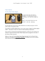
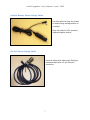
L and R Upgrades – User’s Manual – June 1, 2009
USER’S MANUAL
LRFB-300 FEEDBACK UPGRADE
and
L and R Lithium-Ion BATTERY UPGRADE
©2009 L and R Meter Service, LLC
[email protected]
www.gravitymeter-repair.com
1
L and R Upgrades – User’s Manual – June 1, 2009
TABLE OF CONTENTS
L and R LITHIUM-ION BATTERY UPGRADE ................................................................................ 4
Lithium Ion Battery ............................................................................................................ 4
Lithium Ion Battery AC Charger....................................................................................... 4
Lithium Ion Battery Enclosure .......................................................................................... 5
Power Options ..................................................................................................................... 6
Gravity Meter Power Supply ................................................................ 6
Vehicle Battery Power Supply Cable .................................................... 7
Gel Cell Power Supply Cable ................................................................ 7
L and R FB-300 FEEDBACK UPGRADE...................................................................................... 8
OVERVIEW............................................................................................................................. 9
SPECIFICATIONS:............................................................................................................. 10
HARDWARE ........................................................................................................................ 11
NULLING DIAL CLAMP ....................................................................... 11
ELECTRONIC LEVELS ......................................................................... 11
POWER SWITCH:............................................................................... 12
LCD DISPLAY .................................................................................... 13
DISPLAY of FEEDBACK FACTOR .................................................................................. 14
FEEDBACK CARD ............................................................................... 15
DATA DISPLAY BOARD ...................................................................... 16
GRAVITY METER OPERATION with FEEDBACK............................................................. 17
PRE-SETTING THE COUNTER.............................................................. 17
SURVEY RANGE LESS THAN 300 mGal:........................................................................ 17
SURVEY RANGE GREATER THAN 300 mGal: ............................................................... 17
READING GRAVITY............................................................................ 18
2
L and R Upgrades – User’s Manual – June 1, 2009
DATA LOGGING to PDA via BLUETOOTH ...................................................................... 19
PDA OPERATION ............................................................................... 19
BLUETOOTH CONFIG ................................................................................................... 20
GPS CONFIG................................................................................................................ 21
DATA TRANSFER by SYNC CABLE................................................................................ 22
DATA TRANSFER by SD CARD..................................................................................... 22
PDA SOFTWARE ................................................................................ 23
OVERVIEW.................................................................................................................... 23
STARTUP ........................................................................................................................ 24
“SAVE AS” SCREEN ...................................................................................................... 24
MAIN SCREEN .............................................................................................................. 25
MAIN SCREEN .............................................................................................................. 25
INDICATORS: ........................................................................................................... 25
USER CONTROLS:...................................................................................................... 26
CONFIG SCREEN.......................................................................................................... 29
PDA DATA FORMAT ........................................................................... 31
GRAVITY MEASUREMENT WITH PDA: EXAMPLES ...................................................... 32
Example 1: Field Test over 7 mGal Range.......................................... 32
Example 2: Microgravity: Pier to Floor in Lab .................................... 32
Example 3: Earth Tide Monitoring ..................................................... 33
FAQ (Frequently Asked Questions)..................................................................................... 34
WARRANTY ............................................................................................................................. 35
REFERENCE ............................................................................................................................. 36
APPENDIX................................................................................................................................ 36
Meter Setup with Feedback Installed............................................................................... 36
3
L and R Upgrades – User’s Manual – June 1, 2009
L and R LITHIUM-ION BATTERY UPGRADE
Lithium Ion Battery
Two batteries are supplied with each upgrade.
Lithium Ion Battery AC Charger
Model CH4000
Input: 100-240 VAC 50-60 Hz
24 VDC 2.6A
Output:
Plug “ION BATTERY CHARGER SUPPLY”
into “ION BATTERY CHARGER”. Install one
battery and charge if needed. New
batteries will be charged when you
receive the meter. This charger will
charge a battery in 4.5 hrs.
Note: Do NOT Plug the “ION BATTERY
CHARGER” into the GRAVITY METER
WHITE BOX. This 24V COULD
DAMAGE the GRAVITY METER
ELECTRONICS!
4
L and R Upgrades – User’s Manual – June 1, 2009
Lithium Ion Battery Enclosure
This enclosure on the left side of the White
Box interfaces the Lithium Ion battery to
the Gravity Meter.
5
L and R Upgrades – User’s Manual – June 1, 2009
Power Options
Gravity Meter Power Supply
Use this supply when AC power is
available, i.e. in laboratory for tidemonitoring or for long term storage on
heat.
INPUT: 100-240 VAC 50-60 Hz 1.0A
OUTPUT: 15V 2.6A
40W Max
On the Right side of the Gravity Meter White Box is a small pin plug for 12V DC
power input to the gravity meter.
Plug GRAVITY METER POWER SUPPLY into socket marked “GRAVITY METER POWER
INPUT”. Wait about 3 hours for meter to reach operating temperature.
Once meter has reached the operating temperature, install one of the Lithium-Ion
batteries. Unplug the Gravity Meter Power Supply that is plugged into the side of
the Gravity Meter white box.
When you have the Gravity Meter Power Supply plugged into the Gravity Meter
white box, the battery is NOT BEING CHARGED. The battery will only be charged
while using the Ion Battery Charger.
6
L and R Upgrades – User’s Manual – June 1, 2009
Vehicle Battery Power Supply Cable
Use this cable to keep the meter
on heat during transportation in
a vehicle.
Plug into vehicle (12V system!)
cigarette lighter socket.
Gel Cell Power Supply Cable
Use this cable with older-style Gel/type
batteries that have a 2-pin Cannon
connector
7
L and R Upgrades – User’s Manual – June 1, 2009
L and R FB-300 FEEDBACK UPGRADE
A complete package of long-term meter servicing and modern hardware/software
upgrades. Compatible with all LaCoste & Romberg Model G and D Land Gravity
Meters, the L and R Upgrade Package includes the following:
1- Clean and Adjust and Complete Checkout
2- Replace Seals
3- Clean and Checkout Micrometer Screw
4- Rework Gear-Box
5- Convert Level Lights to Low Heat LED's
(if needed)
6- Convert Reading Light to Low Heat LED's (if needed)
7- External PDA with GPS for Data Logging
8- Replace Glass Thermometer with Digital Temperature/Battery Voltage Monitor
9- Install Liquid Electronic Levels
10- Install Nulling Dial clamp.
11- Install Feedback Board and Data Display Board
12- Add Electronic Readout (CPI) (if needed; additional charge)
13- Rework Aluminum Carrying Case to fit Upgraded Meter
8
L and R Upgrades – User’s Manual – June 1, 2009
OVERVIEW
The L and R Meter Service LRFB-300 feedback system delivers a new level of
accuracy, precision, and reliability. A user-friendly interface enhances customer
convenience. No longer is there any need for a K-Factor lookup table; this system
displays gravity directly in mGal on an easy-to-read LCD display.
The LRFB-300 feedback system has a range of approximately 300 mGal (+/- 150)
with a resolution of 0.001 mGal. The LRFB-300 is covered by our standard
warranty, printed at the back of this manual.
Electronic system
The LRFB-300 upgrade is consists of a linear feedback system with a
microprocessor-controlled 24 bit A/D. The electronics have extremely high gain and
electronic damping which means the meter is more noise-resistant. A digital lowpass filter is applied to average the natural background seismic noise present at
most locations. Default filter length is 40 seconds, and can be set from 1 to 52
seconds in the PDA software.
The electronic level outputs, meter temperature, and battery voltages are also
acquired. All data is transmitted via the Bluetooth serial port on the side of the
meter. This serial data can be recorded by the included PDA and MeterLog software.
PDA Handheld Computer
A full featured data logger records the output of the LRFB-300, via Wireless
Bluetooth, in either field or laboratory conditions.
The gravity logging software, MeterLog, allows input of station name, latitude,
longitude for each station. The GPS enabled Pharos PDA can automatically input the
correct Latitude and Longitude data into the MeterLog software for the automatic
tide correction. Unfortunately the elevation from a single GPS unit is not good
enough for processing elevation corrections. You must set the time to GMT/UTC
time, not local time!
The user can either manually record single data points per station or set the
software to record continuously at the selected time interval. All data gets recorded
to the solid state memory for later transfer to a PC. Data can also be recorded onto
SD flash cards for even more security and ease of data transfer.
9
L and R Upgrades – User’s Manual – June 1, 2009
SPECIFICATIONS:
Principle: Linear Electrostatic Feedback
Range: Approximately 300 mGal (+/- 150 mGal)
Linearity: Better than 0.01% Full Scale
Data Resolution: 0.001
Repeatability: 0.01 to 0.02 mGal
Electronic Drift: < 0.001 mGal /1000 hr. (does not include meter drift)
Feedback Calibration Factor: Set at factory in Flash memory
Digital Display: 2x16 character LCD w/backlight; LCD heater for below -10°C
Output: Wireless Bluetooth Port with 2 Hz Serial data output
Data Format: ASCII text, comma delimited
Power Consumption: 0.2 amp @12 Volts (LCD Heater off)
Input Voltage: 10-15 VDC
Battery Life for Meter: Greater than 15 hours, @ 22°C with LRFB-300 on
* Specifications are subject to change.
10
L and R Upgrades – User’s Manual – June 1, 2009
HARDWARE
NULLING DIAL CLAMP
Use this small knurled screw to lock the
Nulling Dial in place when using the
Feedback system to measure relative
gravity differences. This keeps the dial
from moving between readings.
Be sure to unlock the Nulling Dial before
moving it.
ELECTRONIC LEVELS
The LRFB-300 Feedback Upgrade for LaCoste & Romberg G or D meters includes
installation of electronic levels. All new upgrades use the very robust and stable
ceramic/liquid type.
The user should level the meter with the long and cross galvanometers when using
the LRFB-300 Feedback system. The cross and long level galvanometer needles
indicate level when they are centered.
The old bubble levels are adjusted for manual (optical 10=10 sensitivity) readout at
the factory. We suggest you keep this set up; refer to the Model G & D manual for
further details). Remember that the screw K-Factor table is only valid when the
long sensitivity is set to 10=10 per the manual.
11
L and R Upgrades – User’s Manual – June 1, 2009
POWER SWITCH:
This small 3-Position switch is located on the
black lid, lower right corner, adjacent to the
LCD Display.
The forward position, “ON”, enables on
the LRFB-300 only. The meter and feedback
system will drift less if the LRFB-300 switch
is left ON all day while surveying.
The rear position, “W/LCD HEAT ON”,
turns on BOTH the LRFB-300 system and the LCD heater. This heater enables the
LCD display to function in temperatures below -15° C. It draws extra power and is
not needed above -15° C. With a good battery you should get a full day of use out
of your meter even with the LRFB-300 on constantly unless it is very cold.
The center position, “OFF”, disables the feedback voltage. In the OFF position
the gravity meter can be read manually, i.e. the “classical” method of nulling the
CPI (Electronic Readout) Beam Position Galvanometer and recording the counter
reading as in old G meters.
12
L and R Upgrades – User’s Manual – June 1, 2009
LCD DISPLAY
This 2-line “extended temperature version” LCD
display is installed on the black gravity meter lid.
The display is specified to work in ambient
temperatures of -20° C to +50° C.
With the LCD heater turned on, it has been used
in field conditions down to -40°C. We suggest the
heater be turned on below -10°C.
Do not store the meter below –20ºC with power off. Permanent damage to the LCD
display can occur. If there is power to the meter, and the LRFB-300 power switch is
set to “W/LCD HEAT ON”, there should be no risk of damage.
The LCD display has a back-light to enable
viewing in dark conditions. The backlight can be
toggled ON/OFF using a virtual control on the
CONFIG screen of PDA MeterLog software.
The first line displays relative gravity in
mGal. When the meter is clamped the gravity
display will typically read 200.00, although this
value varies from meter to meter due to small
differences in internal construction.
After leveling and unclamping, the feedback system will stabilize to a gravity
reading ranging (approximately) from +150.xxx to -150.xxx mGal.
The second line displays internal Meter Temperature (in °C) and Battery
Voltage. Each gravity meter has a specific optimum ”nose” temperature, usually
in the range 48°C to 58°C. The indicated meter temperature should remain
constant at this “nose” temperature. In extreme ambient conditions the
temperature may vary by approximately 0.1 °C.
The Battery Voltage is approximately 12V with a fully charged battery. The voltage
can vary about 0.5 Volts as the internal heating circuitry cycles on/off. The battery
should be replaced or recharged if below about 10.4 Volts.
13
L and R Upgrades – User’s Manual – June 1, 2009
DISPLAY of FEEDBACK FACTOR
There is a factory setting called the FEEDBACK FACTOR. It is a gain setting used to
convert digital output of the Feedback Board directly into mGal. This 5-digit number
is typically in the range of 12000 to 29000, and is permanently stored in internal
firmware on the Feedback Board.
It should not be necessary for the user to modify this setting. However, the LRFB300 system can display the current stored value for verification. This may be
helpful in a troubleshooting situation.
The LCD Display will display the FEEDBACK FACTOR (instead of Temp and Battery
Voltage) when commanded to do so via the PDA. The PDA MeterLog software has a
control in the lower right corner of the CONFIG screen labeled READ CONFIG.
When “READ” is pressed, the second line of the LCD display will change to display
a five digit number. This number is displayed with a decimal point between the
second and third digits, i.e. typically in the range of 12.000 to 29.000. When the
PDA CONFIG Screen is EXITed, the LCD Display second line reverts to normal
Temp/Battery Voltage display.
14
L and R Upgrades – User’s Manual – June 1, 2009
FEEDBACK CARD
The L and R Feedback
Card
controls
the
precision DC Voltage
that balances the gravity
meter
electronically.
This card also generates
the necessary signals to
operate the Electronic
Level (Cross and Long)
and Electronic Readout
(CPI) systems.
The Feedback Card is located inside the meter under the black lid. It does not
contain any user-serviceable parts. Note the three small (blue) pots along the card
top. These adjust the cross and long level gain, and the feedback gain. These pots
should NOT be adjusted by user, i.e. only set at the factory. In case of field
problems with the feedback system, particularly after transportation, vibration, or
rough handling, the operator can try carefully re-seating the connectors along the
top of the card.
15
L and R Upgrades – User’s Manual – June 1, 2009
DATA DISPLAY BOARD
The Data Display Board is mounted
in a black plastic enclosure on the
right side of the meter. It contains no
user-serviceable parts. In case of
field
troubleshooting,
particularly
after transportation, the operator can
check the connectors.
Note the smaller board in the top
center; this contains the Bluetooth
transmitter
to
communicate
wirelessly with the external PDA data
logger.
ASCII serial data is continuously broadcast from the Bluetooth radio antenna.
Once the Bluetooth devices are enabled and paired properly, a standard terminal
program such as HyperTerminal (a standard accessory on Windows XP systems).
can capture the Bluetooth data stream.
Serial port settings are: 2400, N, 8, 1. Data packets are transmitted at 2 Hz.
0.244,
0.244,
0.244,
0.243,
0.243,
0.243,
0.243,
0.243,
0.243,
0.243,
0.243,
0.243,
0.243,
0.243,
0.243,
0.243,
0.243,
43,
45,
45,
44,
44,
45,
46,
44,
46,
45,
45,
45,
44,
45,
44,
46,
46,
77,
79,
78,
78,
79,
78,
77,
78,
78,
78,
80,
78,
78,
80,
77,
79,
79,
48.6,
48.6,
48.6,
48.6,
48.6,
48.6,
48.6,
48.6,
48.6,
48.6,
48.6,
48.6,
48.6,
48.6,
48.6,
48.6,
48.6,
11.6
11.6
12.0
12.0
12.0
12.6
12.6
12.6
12.6
12.6
12.6
12.6
12.1
12.1
12.1
12.1
12.1
Note that only Feedback Gravity, Long and Cross Level value, and Meter
Temp/Battery Voltage are transmitted. Time and Lat/Lon coordinates are only
available from the PDA stored file, after PDA appends time and location data.
16
L and R Upgrades – User’s Manual – June 1, 2009
GRAVITY METER OPERATION with FEEDBACK
PRE-SETTING THE COUNTER
SURVEY RANGE LESS THAN 300 mGal:
If you are at roughly the middle of your survey gravity range then the counter
should be adjusted until the gravity indicated in the LCD is close to zero. If you are
at roughly the lowest gravity of your survey range then the Counter should be
adjusted until gravity indicated in the LCD is close to -150.
If you are at roughly the highest gravity of your survey range then the counter
should be adjusted until the gravity indicated in the LCD is close to +150. This will
allow you to use the full feedback range without moving the counter.
SURVEY RANGE GREATER THAN 300 mGal:
There are two methods to consider:
Method 1:
Record “tie” stations on the fly. When the gravity displayed on the LCD is close to
being out of range make two readings at the same station with different counter
settings. If you get out of range go back to the last station that was in range. The
first reading should be at the old counter setting; then re-range the counter to
make the LCD displayed gravity zero (0.0) or close to the opposite end is also
useful in some situations. The difference between these two readings (in mGal) is
an offset that will have to be added to all subsequent readings in processing the
survey.
If you are performing a high accuracy survey you may want to perform this
procedure twice independently; clamp and unclamp the meter after the first set of
readings and then perform another set of readings at the same two counter values.
Then continue on with the survey at the new counter setting as long as possible. In
a large survey you will end up with a large number of these offsets. Keep a careful
record of the counter settings, as they are not recorded by the data logging system.
17
L and R Upgrades – User’s Manual – June 1, 2009
Method 2:
You can break your survey up into sections that can be measured using one counter
setting. Then tie those sections together with base stations that are readable with
counter settings from two survey sections and still be within the feedback range.
It should be noted that the Screw K-Factor table is set up for optical readings and
can be off slightly (< 0.5%) when moving the counter for re-ranging purposes while
using the feedback system level settings. If possible you should use the LCD gravity
readout to tie sections together; it will be more accurate than using the counter. Or
if there is a large gravity difference (>100 mGal) then do a base station tie (using
the bubble levels if present) and optical system only and convert counter readings
to gravity with the K Factor table for that meter. (Reading the meter like an old
optical G-Meter)
READING GRAVITY
All gravity meters are fragile instruments. Data quality (repeatability and accuracy)
is dependent on how carefully the meter is handled during your survey. Minimize
any bumping, shaking, or tilting during the survey.
Be sure to check the vertical settings for both levels before starting your survey or
any time the meter receives a large shock. Refer to the G meter manual for more
information.
The basic reading sequence is as follows:
1- Keep feedback turned ON throughout the entire survey.
2- Level the meter: adjust the black level-rod knobs on the lid until both the
cross and long galvanometer needles are centered.
3- Unclamp meter.
4- Wait for indicated gravity value to stabilize.
5- Record Reading: record the indicated gravity reading on the LCD display, or
log the data wirelessly to the supplied PDA running “MeterLog” software.
6- Clamp Meter, move to next station.
18
L and R Upgrades – User’s Manual – June 1, 2009
DATA LOGGING to PDA via BLUETOOTH
PDA OPERATION
The PDA model provided is the Pharos GPS Model 535v with Windows Mobile
operating system. The user should be familiar with the PDA and he Windows Mobile
operating system; the PDA manual includes troubleshooting tips.
In particular, note:
•
The button at the top center of the PDA is the on/off button. Holding this
button down for a short time will reboot the device.
The location of the SD card, GPS antenna port, and reset button.
•
Overnight charging of battery required before first operation.
•
19
L and R Upgrades – User’s Manual – June 1, 2009
BLUETOOTH CONFIG
Make sure the Bluetooth is turned on. In the Lower Right Corner of the PDA start
screen is a Bluetooth Icon. If it has a red dot with an X the Bluetooth is turned off.
Tap the Bluetooth Icon to turn it on.
20
L and R Upgrades – User’s Manual – June 1, 2009
GPS CONFIG
Refer to the PDA manual for details on configuring the GPS system.
These screens indicate the factory configuration values to use. Leave these as set
at the factory.
21
L and R Upgrades – User’s Manual – June 1, 2009
DATA TRANSFER by SYNC CABLE
Insert CD supplied with Pharos PDA, install “Windows Mobile” i.e. Microsoft
ActiveLink 4.2 software. Connect Pharos PDA to Computer USB port with SYNC
cable supplied with Pharos PDA.
Be sure to install and test this function before starting survey.
DATA TRANSFER by SD CARD
The PDA is supplied with a 1 GB SD memory card. The SD card flash memory is
permanent and will not be lost if the PDA batteries get fully discharged.
The SD card allows easy data transfer to various devices. Many laptops have a
direct SD card slot. If transferring to a desktop computer, consider using an
inexpensive SD-to-USB converter.
22
L and R Upgrades – User’s Manual – June 1, 2009
PDA SOFTWARE
OVERVIEW
The data logging software is named “MeterLog.exe”; an executable file created with
LabView graphical programming language.
There may be name variations in the future to include software version number.
A backup copy of “MeterLog.EXE” program is stored on the 1GB SD card included
with each upgrade.
The PDA handheld computer captures the Bluetooth output of gravity meters
equipped with the LRFB-300 Feedback Upgrade.
FEATURES
Bluetooth Wireless data logging.
Large data capacity
Record data to SD card for secure storage
Automatic or Manual Station Name entry
GPS data integrated into software
Latitude and Longitude
Automatic Tide Correction
Continuous data logging at user selected interval
LICENSE INFORMATION
This program is licensed "AS IS" without warranty of any kind, either expressed or
implied, including, but not limited to, the implied warranties of merchantability and
fitness for a particular purpose. The entire risk as to the quality and performance of
the program is with you.
In no event will L and R Meter Service be liable to you for damages, including any
general, special, incidental or consequential damages arising out of the use or
inability to use the program (including but not limited to loss of data or data being
rendered inaccurate or losses sustained by any other programs), even if L and R
Meter Service has been advised of the possibility of such damages.
“MeterLog” software is © 2009 by L and R Meter Service LLC.
23
L and R Upgrades – User’s Manual – June 1, 2009
STARTUP
Go to the START menu. (Upper Left Corner)
Go to the FILE EXPLORER MENU. Make sure you are in MY DOCUMENTS.
Find the “MeterLog” program Icon, use the PDA stylus to start it.
“SAVE AS” SCREEN
When the program loads, the “SAVE AS” screen is
immediately displayed. Go to the “Location” drop
down menu, and select either
“SD-MMCARD”
(Data stored on removable 1GB SD card).
Or
”Main memory”
(Data stored in PDA MY DOCUMENTS folder).
Once you have selected the SAVE AS location, press
the SAVE box. A YES/NO Dialog Box will pop up,
alerting that the file exists, and asking “Do you want
to replace it”?
Answer should be “YES”!
NOTE: Previous data will NOT be erased; new data
will simply be appended to the file.
24
L and R Upgrades – User’s Manual – June 1, 2009
MAIN SCREEN
INDICATORS:
“Gravity (mGal)” Indicator:
Gravity in mGal
“GPS” Status Indicator:
Green if OK, Black if not OK
“Tide” Indicator:
Computed Tide Correction in mGal
“Long Level” Indicator:
Relative Level Position in bits
“Temperature” Indicator:
Meter Temperature in °C
“Latitude” Indicator:
Latitude in Decimal Degrees
“Cross Level” Indicator:
Relative Level Position in bits
“Voltage” Indicator:
Battery Voltage in Volts
“Longitude” Indicator:
Longitude in Decimal Degrees
“File Path” Indicator:
Default data storage path is “\My Documents\Data.dat”
“Date” Indicator:
GMT Date
“Time” Indicator:
GMT Time
25
L and R Upgrades – User’s Manual – June 1, 2009
USER CONTROLS:
“Tide Corr” Checkbox:
Check this checkbox if you wish Tide Correction to be computed and added to the
observed Gravity. When enabled, MeterLog displays the actual tide value, time,
latitude, and longitude indicators. Warning: The time set on the PDA must be set
to GMT (or UTM) for the tide calculation to be correct. You can introduce errors up
to 0.6 mGal if the Time, Lat, or Long is not correct!
“STATION” Control:
The station ID originally defaults to “LINE 1” or “LINE 2”. You can modify the
station ID to your choice. Highlight the current name, and overwrite using the PDA
alphanumeric keypad and stylus.
“INDEX” Control:
Modify the index to be stored using the stylus on the INDEX up/down control.
The index will increment by one each time you save a reading.
26
L and R Upgrades – User’s Manual – June 1, 2009
“Save_station OK” Control:
When Gravity reading is stable, i.e.
typically 2 minutes after leveling and
unclamping, click “OK” button next to the
“Save_station” label.
The ”SAVE” screen will pop up.
The data about to be recorded is displayed
for review. Hit SAVE to store, or EXIT to
abort saving the reading.
27
L and R Upgrades – User’s Manual – June 1, 2009
“Config” Control:
Click to enter Config Screen. Refer to the “CONFIG SCREEN” page below for
indicators and controls on Config Screen.
“Continuous Recording” Control:
Click to enable continuous recording. A new
screen will open where you can enter the
recording interval.
Select the desired recording interval in seconds,
click “GO” Control to return to Main Screen.
then
“EXIT” Control:
Before you turn off the PDA, you must exit “MeterLog.exe” using the “Exit” control
in the lower right of the main screen. Do NOT close the program with the “X” in the
upper right. Should this happen, you can re-load the program, but it may not
function correctly. (Check the Bluetooth Icon on Start Screen to verify it is
enabled).
28
L and R Upgrades – User’s Manual – June 1, 2009
CONFIG SCREEN
“BACKLIGHT” Checkbox Control:
To turn the Meter
backlight on, check this
SAVE button. Uncheck
press SAVE to turn the
OFF
LCD Display
box and press
the box and
LCD Backlight
“LEVELS RESET” Control:
The meter is leveled visually by
centering the galvanometer needles.
The electronic level outputs are
recorded to the data file in bits ranging
±32000.
When level, recorded outputs are
typically ±100 bits. Level offset values
are applied to the relative level data
before recording. Press the SET Control
to adjust the offsets and bring the outputs closer to zero. The new offsets are then
stored in non-volatile memory on the Feedback Board.
“FILTER” Control:
This displays and controls the length of the low-pass filter applied to the gravity
data. You can change the filter length with the UP/DOWN control. Press “SAVE”
button to store this filter setting onto Feedback Board. Note: At startup, this
control may NOT display the actual Filter length currently stored in firmware on the
Feedback Board. Press “READ CONFIG” Control to update the displayed value.
29
L and R Upgrades – User’s Manual – June 1, 2009
“GPS Lat/Lon” Control Checkbox:
If you wish to use GPS data from the Pharos PDA, check this box. These GPS
coordinate data will then be recorded in the PDA output file.
If you do not wish to use GPS data from the Pharos PDA, uncheck this box.
You can enter LAT/LON information from an external source into the two controls
labeled Latitude/Longitude. Enter in Decimal degrees and Press “SAVE” control.
These external coordinate data will then be recorded in the PDA output file.
“READ CONFIG” Control:
Press “READ CONFIG” button to load the various parameters stored in firmware on
the Feedback Board into the PDA Config Screen. These parameters include the
Feedback Factor and the Filter Length.
This control will also cause the FEEDBACK FACTOR to be displayed on the second
line of the Gravity Meter LCD Display.
When “READ” is pressed, the second line of the LCD display will change to display
a five digit number. This number is displayed with a decimal point between the
second and third digits, i.e. typically in the range of 12.000 to 29.000. When the
PDA CONFIG Screen is EXITed, the LCD Display second line reverts to normal
Temp/Battery Voltage display.
“EXIT” Control:
Press “EXIT” Control to exit CONFIG SCREEN and return to the Main Screen of
“MeterLog” software.
30
L and R Upgrades – User’s Manual – June 1, 2009
PDA DATA FORMAT
Comma-delimited ASCII data file
PARAMETER
UNITS
COMMENT
Stat_ ID
Date
GMT time
Grav
TC_Grav
Tide
Lat
Long
Long_Level
Cross_Level
Temp
Volts
Alphanumeric
3/ 3/2009
19:42:22
mGal
mGal
mGal
Decimal Degrees
Decimal Degrees
±32000 bits
±32000 bits
°C
Volts
Station ID
GMT Date
GMT Time
Gravity
Tide Corrected Gravity
Tide Correction
Latitude
Longitude
Long Level
Cross level
Meter Temperature
Battery Voltage
.
31
L and R Upgrades – User’s Manual – June 1, 2009
GRAVITY MEASUREMENT WITH PDA: EXAMPLES
Example 1: Field Test over 7 mGal Range
”ABABABAB” Repeat Survey Loop
Test performed at L and R Meter Service
Test Range: Lexington, Texas.
Known Diff = 6.58 mGal
Stat_ID,Date, GMT time,Grav,TC_Grav,Tide,Lat,Long,Long_Level,Cross_Level,Temp,Volts
Bottom
Top-1,
Bottom
Top-2,
Bottom
Top-3,
Bottom
Top-4,
-1, 3/
3/
-2, 3/
3/
-3, 3/
3/
-4, 3/
3/
3/2009,19:42:22,3.679,3.696,-0.017,30.409167,-97.093215,-111,54,48.6,11.1
3/2009,19:56:31,-2.944,-2.919,-0.025,30.41723,-97.08487,-50,-101,48.7,11.4
3/2009,20:08:23,3.653,3.685,-0.032,30.409167,-97.093225,-131,95,48.6,11.1
3/2009,20:24:00,-2.982,-2.941,-0.041,30.41714,-97.084828,187,-3,48.6,11.4
3/2009,20:37:15,3.633,3.681,-0.048,30.409167,-97.093223,-191,208,48.6,11.4
3/2009,20:51:00,-2.97,-2.914,-0.056,30.417115,-97.084882,532,90,48.6,11.3
3/2009,21:02:50,3.631,3.693,-0.062,30.409153,-97.093215,3,131,48.6,11
3/2009,21:15:21,-3.01,-2.941,-0.069,30.41716,-97.084923,-66,-22,48.6,11.3
Example 2: Microgravity: Pier to Floor in Lab
Stat_ID,Date, GMT time,Grav,TC_Grav,Tide,Lat,Long,Long_Level,Cross_Level,Temp,Volts
Pier-1,
Floor-1,
Pier-2,
Floor-2,
Pier-3,
Floor-3,
Pier-4,
4/15/2009,21:06:59
4/15/2009,21:11:19
4/15/2009,21:18:07
4/15/2009,21:22:32
4/15/2009,21:26:38
4/15/2009,21:30:38
4/15/2009,21:33:59
PM,
PM,
PM,
PM,
PM,
PM,
PM,
-0.056,-0.064,0.008,0.000000,0.000000,24,-55,48.5,11.9
0.049,0.040,0.009,0.000000,0.000000,76,-36,48.5,11.8
-0.068,-0.077,0.009,0.000000,0.000000,-145,-7,48.5,12.3
0.041,0.031,0.010,0.000000,0.000000,-121,67,48.5,11.6
-0.065,-0.075,0.010,0.000000,0.000000,-23,48,48.5,11.9
0.037,0.027,0.010,0.000000,0.000000,0,-19,48.5,12.5
-0.063,-0.073,0.010,0.000000,0.000000,81,91,48.5,12.6
32
L and R Upgrades – User’s Manual – June 1, 2009
Example 3: Earth Tide Monitoring
Continuous Reading Interval set to 60 seconds.
Stat_ID,Date, GMT time,Grav,TC_Grav,Tide,Lat,Long,Long_Level,Cross_Level,Temp,Volts
LINE1-0,
LINE1-0,
LINE1-0,
LINE1-0,
LINE1-0,
LINE1-0,
LINE1-0,
LINE1-0,
LINE1-0,
LINE1-0,
LINE1-0,
LINE1-0,
LINE1-0,
LINE1-0,
LINE1-0,
LINE1-0,
LINE1-0,
LINE1-0,
4/15/2009,21: 5:22,
4/15/2009,21: 7:23,
4/15/2009,21: 8:23,
4/15/2009,21: 9:23,
4/15/2009,21:10:23,
4/15/2009,21:11:23,
4/15/2009,21:12:23,
4/15/2009,21:13:23,
4/15/2009,21:14:23,
4/15/2009,21:15:23,
4/15/2009,21:16:22,
4/15/2009,21:17:22,
4/15/2009,21:18:22,
4/15/2009,21:19:22,
4/15/2009,21:20:22,
4/15/2009,21:21:22,
4/15/2009,21:22:22,
4/15/2009,21:23:22,
-0.039,0.044,-0.083,30.414493,-97.095028,97,161,48.5,11.6
-0.038,0.046,-0.084,30.411625,-97.092138,88,167,48.5,12.4
-0.036,0.048,-0.084,30.411620,-97.092185,89,167,48.5,12.1
-0.035,0.049,-0.084,30.411620,-97.092185,38,34,48.5,11.7
-0.032,0.052,-0.084,30.411620,-97.092185,33,34,48.5,12.1
-0.040,0.045,-0.085,30.411620,-97.092185,34,34,48.5,11.8
-0.037,0.048,-0.085,30.411620,-97.092185,34,30,48.5,11.7
-0.034,0.051,-0.085,30.411620,-97.092185,39,32,48.5,11.9
-0.036,0.049,-0.085,30.411620,-97.092185,39,30,48.5,12.3
-0.037,0.048,-0.085,30.411620,-97.092185,41,28,48.5,12.2
-0.037,0.049,-0.086,30.411620,-97.092185,47,25,48.5,12.2
-0.034,0.052,-0.086,30.411620,-97.092185,49,24,48.5,12.4
-0.034,0.052,-0.086,30.411620,-97.092185,52,22,48.5,11.5
-0.036,0.050,-0.086,30.411620,-97.092185,58,20,48.5,11.8
-0.036,0.050,-0.086,30.411620,-97.092185,58,22,48.5,12.0
-0.040,0.046,-0.086,30.411620,-97.092185,60,22,48.5,12.0
-0.033,0.054,-0.087,30.411620,-97.092185,61,24,48.5,11.6
-0.037,0.050,-0.087,30.411620,-97.092185,57,28,48.5,12.5
33
L and R Upgrades – User’s Manual – June 1, 2009
FAQ
(Frequently Asked Questions)
Can I re-install the MeterLog software in the PDA?
The File Name is “MeterLog.exe”, and is about 1.5mB.
A backup copy of the MeterLog.exe software is supplied on the 1 GB SD card
provided with the system. (This user manual is also on the supplied SD card)
Can I change the Operating Range of the Feedback system?
No, the range is fixed.
34
L and R Upgrades – User’s Manual – June 1, 2009
WARRANTY
L and R Meter Service LLC repaired and/or upgraded gravity meters are warranted
for a period of 1 year after delivery. At the Purchaser's request, L and R Meter
Service LLC will make all necessary adjustments, repairs and parts replacements.
All parts will become the property of L and R Meter Service on an exchange basis.
This warranty will not apply if such adjustments, repair or parts replacement are
required because of accident, neglect, misuse, operation on improper power,
transportation or causes other than ordinary use.
All necessary adjustments, repair or parts replacement will be made at no charge to
the Purchaser provided that the Purchaser pays all transportation cost to and from
the authorized repair facility at L and R Meter Service LLC, in Lexington, Texas. The
period of the warranty is extended by the length of time that the gravity meter is in
transit and in the laboratory for repairs. The warranty is void if the internal sensing
element is opened by an unauthorized person.
The foregoing warranty is in lieu of all other guarantees expressed or implied, and
all obligations or liabilities on the part of L and R Meter Service LLC, for damages,
including but not limited to consequential damages arising out of or in connection
with the use or performance of the meter.
L and R Meter Service LLC
2636 W FM.696, Lexington, Texas, 78947, USA
Tel: 979-773-4041
Fax: 979-773-4042
[email protected]
www.gravitymeter-repair.com
35
Cell: 512-417-5085
L and R Upgrades – User’s Manual – June 1, 2009
REFERENCE
It is necessary that the operator have a solid understanding of the basic manual
adjustments and meter checks. Refer to the L and R “Model G and D Operating
Manual”, which can be downloaded at:
www.gravitymeter-repair.com/images/gdmanual.pdf
APPENDIX
Meter Setup with Feedback Installed
The maximum gravity accuracy with electronic feedback is obtained with the long
level Galvanometer adjusted not to the old optical sensitivity setting of 10=10, but
to maximum gravity as indicated in the LCD readout. This is how the long
galvanometer is adjusted at the factory and the gravity calibration for the digital
readout will only be correct if the meter is adjusted to this sensitivity (which is
maximum gravity).
The meter should have been on heat for as long as possible, to minimize drift. The
Land R LRFB-300 should be switched on for at least 1 hour. Level the meter using
the Galvanometers. Adjust counter screw till LRFB-300 LCD display is reading close
to zero (0.0) gravity. Note this gravity value. Turn the single level knob on the right
side of the meter (long direction) so that the long Galvanometer needle is about ½
division off center; direction doesn’t matter. Let stabilize for 45 seconds and read
gravity off the LCD display.
Is it higher or lower than the original reading?
CORRECT DIRECTION:
If gravity is higher, then your original setting was wrong and you are now moving
in the correct direction. Turn long level leg again so Galvanometer needle moves
another ½ division in the same direction. Wait 45 seconds again then take a gravity
reading from the LCD. If it is higher then keep repeating these steps until the
gravity value starts to decrease. Then back up just slightly.
36
L and R Upgrades – User’s Manual – June 1, 2009
WRONG DIRECTION:
If the gravity reading from the LCD is lower than the previous reading then you
went in the wrong direction and need to turn the leveling leg knob in the opposite
direction. The level Galvanometer needle should move back in the opposite
direction also. Now follow directions under “CORRECT DIRECTION”.
These steps will get you to a maximum value for gravity. You should repeat the test
using even smaller movements of the level Galvanometers for increased accuracy.
Next you need to mechanically re-zero the level so the Galvanometer needle is
centered. With a small screwdriver loosen screw on “long adj” cover plate. Turn the
cover out of the way but do not remove. Using the long hex key (sometimes called
allen wrench or key) provided put it into hole vertically and locate the correct
adjustment screw. Make sure the allen wrench is properly seated then turn slightly.
Note which direction the Galvanometer needle moved in. If the direction of
movement of the Galvanometer needle was correct (towards the center) then keep
turning the adjustment wrench until the Galvanometer needle is centered,
otherwise reverse the direction. You should not have to move it very far (less than
1 turn). The long level Galvanometer is adjusted properly now.
The same procedure may be used to adjust the cross Galvanometer, just substitute
“cross” for “long” in the above directions. The only complication is that when you
move one of the knobs on the LEFT side of the meter (Cross legs) to change the
cross level setting, the long level changes also. You will have to re-level the long
level direction every time you move in the cross direction also. Rotate the small
covers to close back up the openings for the level adjustment and lightly tighten
the small screws.
The cross bubble and cross Galvanometer readouts should indicate the same
position as they are both adjusted to maximum gravity anyway. Only the long
(sensitivity) axis may have different settings for the Galvanometer and the bubble
levels.
It should be noted that the Screw K-Factor table is set up for optical readings and
can be off slightly (< 1%) when moving the counter for re-ranging purposes while
using the feedback system.
37