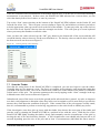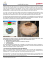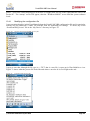
1
E PortaSCAN XBS User Manual A Portable Density Gauge for Wooden Structures Version 5.4 Final: 1 February 2014 – Mark II Model (Getac PDA) PortaSCAN XBS User Manual 1. WARRANTY 1.1 Isoscan Ltd-Manufactured Equipment The PortaSCAN XBS (equipment) is warranted against defects in materials and workmanship for a period of twelve months from date of acceptance performance tests, provided that the equipment has been used in a proper manner as detailed in the following user manual. During the warranty period, repairs or replacement will be made at Isoscan Ltd’s option on a return-to-factory basis. All transportation costs (including insurance) to Isoscan Ltd, except for defects discovered upon initial operation, shall be paid by the Customer. All transportation costs to return the repaired instrument will be paid by Isoscan Ltd. The Customer must obtain shipping instructions and authorisation from Isoscan Ltd before returning the equipment to Isoscan Ltd through PortaCAT Industries Pty Ltd (PCI). Compliance with this provision by the customer shall be a condition of this warranty. In authorising return shipment, Isoscan Ltd shall not be deemed to have assumed any responsibility or liability and, if upon receipt of the equipment, Isoscan Ltd determines that it is not defective in terms of this warranty, the Customer shall pay to Isoscan Ltd, through PCI, upon invoice, the cost of the diagnosis and the cost of the return transportation. This warranty shall not apply to equipment that has been modified or serviced by other than Isoscan Ltd service personnel, or to failure caused by defective parts or components not manufactured by Isoscan Ltd. Isoscan Ltd shall be under no obligation to furnish warranty service (preventative or remedial): (1) if adjustment, repair or parts replacement is required because of accident, neglect, misuse, failure of electrical power, air conditioning, humidity control, transportation, or causes other than normal use; (2) if the equipment is maintained or repaired or if attempts to repair or service equipment are made by other than Isoscan Ltd personnel without the prior approval of Isoscan Ltd. 1.2 Equipment Not Manufactured by Isoscan Ltd Isoscan Ltd’s twelve-month warranty applies only to equipment manufactured by Isoscan Ltd. Although Isoscan Ltd may supply, as part of equipment, parts or components manufactured by other companies, the only warranty that shall apply to such parts or components is the warranty offered by the original manufacturer of the parts or components. Isoscan Ltd will supply such warranty information on request. No representation or guarantee, or other warranty is given or implied in respect of the equipment. 1.3 Software Isoscan Ltd warrants proper system operation only with software programs developed by Isoscan Ltd using the operating system supplied to the Customer. Isoscan Ltd assumes no responsibility for user-written programs. Expert assistance for software development is available and can be contracted to Isoscan Ltd through PCI. 1.4 Out-of-Warranty Repairs Any equipment no longer in its warranty period may be returned, freight prepaid, to Isoscan Ltd through PCI for repair by arrangement. All correspondence concerning repairs should include the model and serial numbers, and a description of the observed problem. For equipment out-of-warranty, the Customer must supply a purchase order number for the repair before the item is returned. Return shipping expense on out-of-warranty repairs will be charged to the Customer through PCI. 1.5 Shipping Damage Shipments should be carefully examined when received for evidence of damage caused by shipping. If damage is found, immediately notify PCI and the carrier making delivery and preserve all documentation. PCI and Isoscan Ltd will provide all possible assistance in processing damage claims. NOTE Isoscan Ltd (and its parent company, the Institute of Geological Sciences Limited) exclude to the full extent permitted by law, liability in contract, tort or otherwise, for any loss, damage or expenses, direct, indirect or consequential, and howsoever caused, whether through negligence or otherwise resulting from any failure or inaccuracy of the PortaSCAN XBS or from any person or organisation’s use or reliance on the PortaSCAN XBS. © PortaCAT Industries Pty Ltd 2014 Page 1 PortaSCAN XBS User Manual Table of Contents 1. WARRANTY ........................................................................................................ 1 1.1 1.2 1.3 1.4 1.5 Isoscan Ltd-Manufactured Equipment ....................................................................... 1 Equipment Not Manufactured by Isoscan Ltd ............................................................ 1 Software .................................................................................................................... 1 Out-of-Warranty Repairs ........................................................................................... 1 Shipping Damage...................................................................................................... 1 2. Introduction to the PortaSCAN XBS User Manual ......................................... 4 3. Principle of the PortaSCAN XBS ...................................................................... 6 4. Introduction to Radiation .................................................................................. 9 5. Safe Work Practices ........................................................................................ 11 5.1 5.2 5.3 5.4 5.5 5.6 5.7 5.8 General ................................................................................................................... 11 Transport ................................................................................................................ 11 Storage ................................................................................................................... 11 Routine work ........................................................................................................... 11 Field Work Practices ............................................................................................... 12 PortaSCAN XBS Design Safety Features ............................................................... 12 Labelling ................................................................................................................. 12 Emergency Procedures ........................................................................................... 12 6. Components of the PortaSCAN XBS ............................................................. 14 6.1 6.2 6.3 6.4 6.5 6.6 6.7 6.8 6.9 6.10 Housing................................................................................................................... 15 Aerial....................................................................................................................... 15 Handheld PC........................................................................................................... 15 Batteries and Recharger ......................................................................................... 15 Handle .................................................................................................................... 15 LEDs and Operating Buttons ................................................................................... 15 Shutter and Indicators ............................................................................................. 15 Detector and Proximity Switch................................................................................. 16 Source Lock ............................................................................................................ 16 Hot Stick Attachment ............................................................................................... 17 7. Operation of the PortaSCAN XBS .................................................................. 18 7.1 7.2 7.3 7.4 7.5 7.6 7.7 7.8 7.9 7.10 Assembly ................................................................................................................ 19 Power On ................................................................................................................ 20 Activate Software .................................................................................................... 21 Enable the Unit ....................................................................................................... 24 Measure the Background Radiation – “Null” ............................................................ 25 Measure or Enter the Timber Density ...................................................................... 26 Scan the Timber ...................................................................................................... 28 Modify the Variables................................................................................................ 31 View the Results ..................................................................................................... 33 Saving a Scan and Entering a Note (with Asset ID)................................................. 34 © PortaCAT Industries Pty Ltd 2014 Page 2 PortaSCAN XBS User Manual 7.11 PortaSCAN XBS Reference Sheet .......................................................................... 35 8. Interpreting the Scan Results......................................................................... 36 8.1 8.2 8.3 8.4 Initial Bar Graph ...................................................................................................... 36 Strength Calculation (Cross Section and Tip Strength) ........................................... 38 Current Condition Estimate ..................................................................................... 39 Screen Capture of the Results ................................................................................ 39 9. Retrieving the Data .......................................................................................... 41 9.1 9.2 10. Note Text Files ........................................................................................................ 42 Image Files ............................................................................................................. 43 Maintenance of the PortaSCAN XBS ........................................................ 45 10.1 10.2 10.3 10.4 Device Pairing ......................................................................................................... 45 Wipe Test ................................................................................................................ 52 Battery Charging ..................................................................................................... 54 Pocket PC ............................................................................................................... 54 10.4.1 Modifying the configuration file ................................................................. 55 10.4.2 Adding the Screen Capture file ................................................................. 57 10.4.3 Re-setting the Pocket PC ......................................................................... 60 10.4.4 Revising the Safety Factor setting ............................................................ 61 Attachment One .................................................................................................... 64 © PortaCAT Industries Pty Ltd 2014 Page 3 PortaSCAN XBS User Manual 2. Introduction to the PortaSCAN XBS User Manual Due to the PortaSCAN XBS being a new technology to the industries that manage timber assets, operators will need to become proficient in its use prior to introduction into an organisation. It is highly unlikely that staff will have experience in this technology. As a result, the training session needs to be reasonably broad and encapsulate some elements of both the use of the PortaSCAN XBS and the associated radiation safety elements to ensure proper and safe use. The Elements of Competency and Performance Criteria associated with learning about the PortaSCAN XBS are as follows: Elements of Competency EC1 Understanding Radiation Safety and a Safe Working Environment EC2 Understanding Principles of Operation of the PortaSCAN XBS EC3 Demonstrate PortaSCAN XBS maintenance procedures EC4 Demonstrate how and when to use the PortaSCAN XBS © PortaCAT Industries Pty Ltd 2014 Performance Criteria Basic knowledge of radiation, including international standard units and properties, are explained. Hazards of radiation and biological effects are identified and explained. Principles of radiation safety are explained, namely exposure reduction – factors of time, distance and shielding; storage and transport of sources. Procedures for dealing with x-ray source emergency are demonstrated. Assessing risks and hazards during transport and use. Security of the PortaSCAN XBS is understood and articulated. Components of the PortaSCAN XBS, namely housing, software, source, detector, power supply, communications, electronics, accoutrements and handheld PC are identified and explained. Knowledge of the overall principles of the PortaSCAN XBS are explained; source and detector, communications, projections and attenuation. Knowledge of PortaSCAN XBS software is demonstrated. Clean housing and accoutrements to PortaSCAN XBS specifications Source and detector are calibrated to within PortaSCAN XBS specifications Software and handheld are tested according to PortaSCAN XBS specifications Images and data are retrieved from handheld PC to screen or alternative data storage The PortaSCAN XBS is stored and transported according to PortaSCAN XBS User Manual and relevant transport standards Personal Protective Equipment is maintained appropriately The PortaSCAN XBS is started up using the procedure outlined in the User Manual Obstacles to the use of the PortaSCAN XBS are identified and preventative measures adopted Pole condition is initially assessed according to client Inspection Guide The scanning principles that apply to the use of the PortaSCAN Page 4 PortaSCAN XBS User Manual Elements of Competency EC5 Identify what may go wrong and what to do EC6 Interpret Scanning Results © PortaCAT Industries Pty Ltd 2014 Performance Criteria XBS are applied according to the User Manual The PortaSCAN XBS is used safely and correctly Traditional inspection methods are used where PortaSCAN XBS is unable to be operated The PortaSCAN XBS is shut-down according to the User Manual Types of faults and their likely cause are identified Identified faults are rectified according to the User Manual, Radiation Safety Plan and Workplace Health and Safety Assistance from a supervisor or qualified repairer is sought if equipment failure continues Components of scan result are identified and their significance explained (scan, variables and notes) The combination of scan result elements are used to ascertain pole condition according to Inspection Guide levels Assistance from supervisor or engineer sought when a scan result is unable to be determined Page 5 PortaSCAN XBS User Manual 3. Principle of the PortaSCAN XBS PortaSCAN XBS is an inspection device that is used to assist an operator to assess the integrity of a wooden structure. The wood is expected to be seasoned, dry timber, as it cannot distinguish between water and wood. It compares the response of a suspect surface to a sound surface, and a loss of response is interpreted as a loss of depth in the surface, with sensitivity to around 100mm. The response loss could equally be a loss in density through the bulk of the object. An operator can then use this information as an aid for assessing the overall integrity of the wooden structure. In the case of power poles, the PortaSCAN XBS goes further and can also provide an estimate of the available bending moment of the pole. In summary, the PortaSCAN XBS is a portable density gauge that uses gamma rays to identify variations in timber density. The concept is for a portable, safe, quick and simple tool to assist inspectors in understanding what lies beneath the surface of the timber they are inspecting. Through robustness in design and with a number of safety features, the user and the public is protected from any risk associated with its use. The PortaSCAN XBS instrument is predominantly made of either two metal boxes (one for the electronics and one for the source housing) or a polycarbonate box for the electronics and a metal box for the source housing. The unit contains a radioactive source of low energy gamma rays and a gamma ray detector. The source is contained within a shuttered brass enclosure and, when abutting a surface, can be instructed to emit a pencil beam gamma rays. These gamma rays penetrate the surface, to a depth of up to 150mm and scatter off the electrons of the substrate atoms. Those that scatter through angles close to 180o i.e. are ‘backscattered’, may be detected by the detector within the instrument. The rate of detection is dependent on the density of the substrate material (which, for light elements, is the same as the electron density) and the thickness of the surface. The sensitivity of the technique is such that any holes, or lower density material, hidden by the surface can be detected down to about 150mm. This is the principle by which PortaSCAN XBS can be used to inspect the integrity of wooden structures. With beams and poles it is the outer timber than provides the strength (available bending moment through the section modulus) and central holes can be quite large before significant loss of strength results. This is illustrated in Figure 1. for a 360mm pole: Figure 1. Bending moment calculation to central hole radius section modulus 360m m diam eter - central internal hole 5,000,000 4,500,000 4,000,000 3,500,000 3,000,000 2,500,000 2,000,000 1,500,000 1,000,000 500,000 0 analytic numerical 0 50 100 150 200 hole radius, m m © PortaCAT Industries Pty Ltd 2014 Page 6 PortaSCAN XBS User Manual Where there has been a loss of wall thickness due to internal degradation, then scanning measurements provided by an instrument such as PortaSCAN XBS are necessary to estimate the remnant strength of a pole of beam. If, through backscatter, it is established that any possible internal hole is less than a maximum size, then a minimum section modulus and strength is implied. The PortaSCAN XBS is a quick inspection tool to achieve this. Figure 2. shows how the backscatter rate varies both with the density of different species of wood, and with the thickness of that wood. Cedar has the lightest density, and quila the heaviest. Clearly, if backscatter rates are to be used to determine wall thicknesses, then the density of the wall must be known. This analysis is implicit in the operation of PortaSCAN XBS. Figure 2. Net backscatter rates against timber type and wall thickness Fig. 2: net backscatter rates 14,000 13,000 12,000 11,000 10,000 9,000 8,000 7,000 6,000 5,000 cedar pine rimu quila jarrah 4,000 3,000 2,000 1,000 0 0 20 40 60 80 100 120 140 160 180 200 mm wall The instrument uses a 25mm NaI(Tl) detector coupled to a photomultiplier to measure the gamma rate from an AMC26 Am241 sealed gamma ray source. The energy of the gamma rays is 60 keV, equivalent to xrays in energy. Emission from the source is tightly collimated and can only be enabled by applying power to a solenoid. Furthermore, except for a calibration procedure, a surface proximity switch is used to ensure that the shutter will only open when the instrument is placed on the surface to be measured. The position of the shutter (open or closed) is indicated by lights on the panel facing the operator. Because the solenoid is springloaded, there can be no emission in the unpowered state. Also, the shutter can also be locked to avert unauthorised use, irrespective of it being in a powered or unpowered state. © PortaCAT Industries Pty Ltd 2014 Page 7 PortaSCAN XBS User Manual The electronics includes a microprocessor with a Bluetooth radio transceiver for short-range digital communications. On request, the microprocessor sends the number of gamma rays counted over a 200 millisecond period, along with the status of the shutter. Communications by the PortaSCAN XBS that is sent by Bluetooth is received by a pocket PC (PPC). Either the menu on this, or buttons on the scanner electronics box, can be used to implement the basic functions. Results are immediately available to the operator and data can be archived for later retrieval and display. © PortaCAT Industries Pty Ltd 2014 Page 8 PortaSCAN XBS User Manual 4. Introduction to Radiation Essentially, radiation is energy that travels through a medium (such as metal or water) or through space, ultimately to be absorbed by either that medium or another. The idea of radiation is exactly that – it is energy that radiates (travels in straight lines in all directions) from a source. Radiation includes the electromagnetic spectrum i.e. visible light, radio waves, infrared, ultraviolet and xrays. The spectrum is measured in terms of the length of wave in metres (the SI or International Standard unit for distance) and the frequency of the cycle of the energy per second is labelled in terms of hertz. A summary of the electromagnetic spectrum is provided in Figure 3.. Figure 3. Electromagnetic Spectrum Electromagnetic Spectrum Frequency (Hz) 104 108 Radio Microwave 103 10-2 1012 1013 Infrared Visible 10-5 10-6 1015 1016 1018 1020 Ultraviolet X-Ray Gamma 10-8 10-10 10-12 Wavelength (metres) This manual focuses on is called ionising radiation i.e. the radiation has enough energy to cause an electron to be ‘knocked out’ of an atom’s electron shells and give the atom a positive charge. Radiation as we know it had its discovery across several renowned experimentalists, the foremost being Marie Curie in terms of actually discovering the behaviour of this energy and naming it “radioactivity”. Ernest Rutherford discovered the types of radiation in the early twentieth century and his research led to him naming the three types of radiation, namely alpha, beta and gamma. Alpha radiation is the result of decay from large nuclei. Because it has a high mass, it is readily stopped by skin or paper. Beta radiation consists of two forms, beta-plus and beta-minus. Beta-minus consists of an ‘energetic’ electron and can be stopped with a few centimetres of metal. Beta-plus is the emission of ‘positrons’ that, due to them be ‘anti-matter’, are annihilated by nearby electrons when they slow down, thereby releasing gamma photons. Gamma radiation is the main focus of this manual and it consists of photons, which are packets of energy that have neither mass nor charge. It is the excess energy created after it has emitted alpha or beta radiation and penetrates much further than either of them. It is due to its penetration properties that it is used in applications such as the PortaSCAN XBS. There are biological i.e. physical effects to radiation exposure and what it does to various parts of the body that any person involved in the radiation industry must be aware of. Heavily ionising particles such as alpha particles and neutrons are more damaging for the same absorbed dose from lighter ionising particles e.g. beta particles or gamma radiation. In physics, a weighting factor is applied to take into account the variation in biological effects on different parts of the body with the level of absorbed dose with the weighting factor applied called the “equivalent © PortaCAT Industries Pty Ltd 2014 Page 9 PortaSCAN XBS User Manual dose”. The SI unit for the equivalent dose is the Sievert, represented by “Sv” and usually referred to in “milli” or “micro” doses e.g. 50 microSieverts (50Sv). The effect of radiation is to potentially alter the chemical or DNA structure of molecules within the human body, thus when a cell divides, it does so with those minor changes and can affect the healthiness of the cell itself. This is quite natural, and happens all of the time. Generally the body heals these minor alterations or the cell dies or is rejected. With substantial radiation doses the cell transformation is such that its function is impaired and the body is unable to repair or reject it, potentially leading to cancers or mutations. Natural background radiation is the highest source of radiation doses for the general public and represents nominally about 3 times the average dose from medical x-rays. Air travel and other sources contribute minimally to most people’s level of radiation received. The recommended annual dose for people who work with radiation is 20mSv and exposure for the public is 1mSv per year. These limits are set in such a way that by reaching them the person remains within an acceptable level of risk for any detrimental affects. © PortaCAT Industries Pty Ltd 2014 Page 10 PortaSCAN XBS User Manual 5. Safe Work Practices The three simple rules to minimise personal radiation doses are: Time: Distance: Shielding: Minimise exposure time Keep as far away as practicable from the radioactive substances Add additional shielding To ensure radiation doses to all persons are minimised, the following practices must be followed: 5.1 General All maintenance work on the PortaSCAN XBS related to the source is only conducted by person authorised to do so and is sent to them for that purpose. Generally, this will be the manufacturer – Isoscan Ltd, New Zealand. For safety reasons the PortaSCAN XBS may only be stored in premises that comply with the Radiation Safety and Protection Plan. 5.2 Transport The packaging and transport of radioactive substances are to be in compliance with applicable Transport Codes as per the Radiation Management Plan. Except in emergency situations, a PortaSCAN XBS must only be transported with the shutter locked in the shielded position and also stored in its transport case (or a similar sturdy container) that is designed for strength and rigidity. The PortaSCAN XBS should be effectively immobilised within the transport vehicle and in most countries and territories may be transported by road without the need for dangerous goods signage. A consignment note specifying that it is a ‘Radioactive Excepted Package UN2911” must be correctly entered in the package details field. This is because the radioactive sealed source used in the PortaSCAN XBS is type-approved with Special Form Certificate, and is properly contained in a safe enclosure, a PortaSCAN XBS instrument is not shipped as a radioactive package. Instead, it designated under UN2911 as an Excepted Package. This package can be shipped as standard freight. 5.3 Storage When a PortaSCAN XBS is due for service and is returned to PortaCAT Industries Pty Ltd, they must be stored in premises, which have been certified as meeting the Radiation Safety Plan. A PortaSCAN XBS placed in the store must be stored with the source assembly locked in the shielded position. If a PortaSCAN XBS cannot be stored in this manner, the placement of such equipment into the store must be closely supervised by the Radiation Safety Officer or Principal Licensee to ensure that the radiation beam is properly attenuated. The record of the location of the PortaSCAN XBS is to be updated. 5.4 Routine work No work should be conducted next to PortaSCAN XBS whilst it is in operation. When not in operation, the PortaSCAN XBS should be stored within its transport case. © PortaCAT Industries Pty Ltd 2014 Page 11 PortaSCAN XBS User Manual 5.5 Field Work Practices When in the field the user must follow the below procedures to minimise public and personal exposure: a) The user must be present at all times to monitor the PortaSCAN XBS and ensure a safe working area of at least 5 metres from the structure being scanned; b) When the PortaSCAN XBS has finished the scan and is removed from the pole, the shutter must be checked to ensure it is in the closed position; c) The operation procedures for the PortaSCAN XBS must be followed at all times; d) The electronics of the PortaSCAN XBS may remain activated in the field for scanning more than one pole in a session, however the unit must be transported with the shutter locked; and e) At all times the operation of the PortaSCAN XBS is to be conducted with safety of the public and operators of primary consideration. 5.6 PortaSCAN XBS Design Safety Features Safety is inherent in the design of the PortaSCAN XBS: 1. The radioactive source is shielded by a brass block of sufficient thickness to reduce the gamma radiation to safe levels. 2. Gamma ray emission is only possible as a pencil beam formed by a deep hole in the block. 3. This beam is turned on and off by a solenoid-controlled shutter. 4. Opening of the shutter is governed by a proximity switch i.e. the gamma ray exit hole must be close to a solid surface for the shutter to be opened. 5. A keyed lock over-rides the operation of the proximity switch and therefore the shutter. 6. Dismantling of the PortaSCAN XBS assembly is inhibited through the used of security screws. 7. A number of visual (Light Emitting Diode or LED) and audio indicators advise the operator of what is occurring with the operation of the PortaSCAN XBS 8. The overall robust design is built to withstand all of the field environments that an operator will be working in. 5.7 Labelling At all times the PortaSCAN XBS must have the label visible and not obscured. 5.8 Emergency Procedures In the case of an incident occurring: 1. Assess the nature and scope of the hazard. Take actions that will prevent further damage or contamination (if contamination is a possibility) if possible. 2. Implement actions to bring the incident under control: Secure the area and evacuate the area to a 5 metre radius. 3. Immediately report the incident to the responsible person and the relevant regulatory authority. 4. Investigate the circumstances of the incident to determine by measurement and calculations the required optimum corrective action plan with instruction from the responsible person and relevant regulatory authority. 5. Prepare a detailed report as soon as possible after the incident and submit it to the relevant regulatory authority within 7 days through the responsible person. 6. Advise the responsible person and relevant regulatory authority on changes required to prevent a recurrence. © PortaCAT Industries Pty Ltd 2014 Page 12 PortaSCAN XBS User Manual When an incident occurs, the following are Names and Addresses and contact phone numbers of: Radiation Safety Officer: Anthony Lima M: 0416 161 090 E: [email protected] Relevant regulatory Authority: Radiation Health Branch Grace Vaughan House 227 Stubbs Terrace SHENTON PARK W A 6008 Telephone: Facsimile: (08) 9388 4999 (08) 9382 0701 This list is to be updated every 12 months or whenever a change occurs and is to be carried with the PortaSCAN XBS at all times Regular Maintenance Maintenance is conducted as per the Radiation Safety Plan for the organisation and the PortaSCAN XBS, which is summarised as: Visually inspect the PortaSCAN XBS prior to daily use. Prior to operational use, each day check normal operation of the unit and that fail-safes are operating correctly On a weekly basis ensure that the unit is not mechanically damaged. © PortaCAT Industries Pty Ltd 2014 Page 13 PortaSCAN XBS User Manual 6. Components of the PortaSCAN XBS There are a number of key components to the PortaSCAN XBS that an operator needs to be familiar with. These are shown in Figures 4. and 5. Figure 4. Figure 5. Control face and accoutrements for PortaSCAN XBS Scanning face of PortaSCAN XBS © PortaCAT Industries Pty Ltd 2014 Page 14 PortaSCAN XBS User Manual 6.1 Housing The housing of the PortaSCAN XBS is made up of two components – one for the electronics and the second for the source and detector. The electronics housing may be made of either steel or polycarbonate but the source and detector housing is always made from aluminium. Because of the sensitivity and protection required for the electronics and the particular safety features required of the source, the housing uses security screws and is water resistant. The source itself is encapsulated by a brass block to make it highly robust and to eliminate accidental exposure to radiation. 6.2 Aerial The aerial is screwed on and off, so that it is easy to store and replace. Just place the base of the aerial onto the coupling provided at the top of the housing and then once it is seated, screw into place. Although the PortaSCAN XBS works at a small distance without the aerial, using it provides a range of about 15 metres and is necessary for cross arm scanning. 6.3 Handheld PC The handheld PC is what runs the PortaSCAN XBS software and controls most of the functions. Although the PortaSCAN XBS will start and limited functions can occur, no scanning result or condition assessment can occur without the handheld PC. Further details on how the handheld PC is used are provided further in the manual. 6.4 Batteries and Recharger To allow operators to continue the use of the PortaSCAN XBS in case the batteries run low, the off-the-shelf lithium ion batteries can be attached on either side of the electronics box housing. They can only be attached one way and are good for about 2 hours continuous use (full day effective use). These batteries are chosen for their ability to last for a day’s use in the field, to be easily replaced (both when run down and if damaged) and quickly recharged. Two sets of dual batteries are provided with each PortaSCAN XBS and the recharger is included in the package. 6.5 Handle The aluminium handle comes in two pieces and is screwed together where at the end where the brass fittings are located. Once screwed into place, the non-handle end is what is placed onto the Handle Attachment rod at the top of the PortaSCAN XBS with the flat edge on the same side as the securing screw. 6.6 LEDs and Operating Buttons To manage the operations of the PortaSCAN XBS there are four buttons on the face of the unit. To provide a visual representation of what function or stage the PortaSCAN XBS is performing there are also four LED indicators alongside the Operating Buttons. These are explained in more detail as part of the operations section. 6.7 Shutter and Indicators The operation of the shutter is key to the performance and safety of the PortaSCAN XBS. The Source Shutter is what prevents radiation from continually emitting from the unit. You can see in Figure 5 where the shutter is located by the small black circle on the top of the image. To show the operator what position the shutter is in during use, Figure 4. has referenced the Shutter Indicator that is either “Closed” or “Open”. When in the “Open” position DO NOT place your hand over the Shutter (black dot). © PortaCAT Industries Pty Ltd 2014 Page 15 PortaSCAN XBS User Manual 6.8 Detector and Proximity Switch Located adjacent to the Shutter (source) is the detector and the Proximity Switch. To explain, the proximity sensor is a circular arrangement that sits behind the surface where the radiation symbol is indicated. The circle has only a small edge and the centre is hollow, allowing the energy from the backscatter radiation to pass through to the detector. When timber comes close to the surface of the detector it interrupts the electromagnetic field of the proximity sensor, triggering the PortaSCAN XBS to activate the solenoid that opens the shutter, if the shutter has been ENABLED. Once the electromagnetic field is no longer interrupted i.e. the timber has moved away from the surface, the proximity sensor turns off the solenoid and the shutter closes (which is its natural position). 6.9 Source Lock When not in use and, in particular for transport of the PortaSCAN XBS, the Source Lock must be turned to the “Shutter Lock” position. A key is supplied with the PortaSCAN XBS unit for this purpose. What the Source Lock does is to move a bar towards or away from the Shutter Indicator. The key lock is situated as shown in Figure 6. and the operator turns in the arrow direction indicated to lock/unlock the shutter. Figure 6. Shutter Lock with key in place. When the Shutter Lock is active, the bar holding the shutter in place is visible as shown in Figure 7. Figure 7. Shutter Lock engaged Once the key is turned counter-clockwise, the bar disengages and the shutter is now able to be operated through the normal use of the PortaSCAN XBS. The position of the Shutter Lock being disengaged is shown in Figure 8. Figure 8. © PortaCAT Industries Pty Ltd 2014 Shutter Lock disengaged. Page 16 PortaSCAN XBS User Manual 6.10 Hot Stick Attachment For the purpose of allowing the PortaSCAN XBS to be used for measuring timber density higher up a pole or on a cross arm, the case includes a hot stick attachment. This is shown in Figure 9. and is attached similarly to the handle. It is not intended to show how a hot stick is used in this manual, as that is the subject of separate training that inspectors would complete. Figure 9. Hot Stick attachment © PortaCAT Industries Pty Ltd 2014 Page 17 PortaSCAN XBS User Manual 7. Operation of the PortaSCAN XBS The steps to using the PortaSCAN XBS are shown on the unit, but simply they are: Power On (Pocket PC and PortaSCAN XBS). Activate PortaSCAN XBS software. Once Comms established, “Enable”. Measure “Null” reading. Measure or Enter “Density” value of timber being scanned. Scan. If scanning a circumference: Modify variables (diameter, height and species). Review “Calculated Results” page. For any scan a “Note” can then be made to save the file. Power Down or make another scan. If scanning a different piece of timber, re-measure or enter the “Density”. If at a location some distance from the earlier “Null” reading, re-measure the “Null” count. Instructions on the PortaSCAN XBS are shown in Figure 10.: Figure 10. PortaSCAN XBS Instructions These steps are outlined in detail in this section. © PortaCAT Industries Pty Ltd 2014 Page 18 PortaSCAN XBS User Manual 7.1 Assembly There are several items within the transport case that are needed to assemble the PortaSCAN XBS ready for use. These are the antenna, two batteries (there are two spares) and the handle. Firstly, with the handle, the two pieces simply screw in together where the fittings are provided. Once the two pieces are attached, the handle is then secured to the PortaSCAN XBS by placing over the shaft piece and tightening the screw. Figure 11. shows the handle approaching the shaft piece, with the screw over the detent in the boss. Figure 11. Handle attaching to the PortaSCAN XBS. The second assembly is the placing of the antenna to the PortaSCAN XBS unit. The antenna is affixed to an adaptor right next to where the handle is attached. As in Figure 12., simply place the antenna into the adaptor then tighten the plastic (blue) nut. Figure 12. Attaching the antenna. © PortaCAT Industries Pty Ltd 2014 Page 19 PortaSCAN XBS User Manual Finally the batteries are placed on either side of the PortaSCAN XBS main housing. Two batteries must be affixed for the unit to work. After taking two of the batteries out of the case, place the end of the battery with the four dots pointing outwards to the base of the battery holder as in Figure 13.. There are two guides on either side of the battery holder that fit within the battery itself to make sure it is aligned. Figure 13. Placing the battery into position. Once placed as in Figure 13., simply push the battery all the way into the holder and it should ‘snap’ into place and remain secure until removed. Figure 14. shows the battery in place. Figure 14. Battery in position. Placing the second battery is a repeat of the first. 7.2 Power On Once the batteries and antenna are attached, the PortaSCAN XBS is ready to have the power turned on. This is done by pressing the “POWER” button as highlighted in Figure 15. These buttons require a reasonably firm press to activate. © PortaCAT Industries Pty Ltd 2014 Page 20 PortaSCAN XBS User Manual Figure 15. PortaSCAN XBS Power Button Once pressed, the “Source OFF” LED turns on green and stays on whilst the shutter is closed and power is going to the unit. When the source is active, the green LED turns off and the “source ON” LED turns on (red). The “comms” LED indicator also starts flashing blue every 5 seconds letting the operator know it is ‘searching’ for a pairing with a device (the Pocket PC). Figure 16. Power and Comms indicators 7.3 Activate Software When the Power on the PortaSCAN XBS is turned on, then turn on the Pocket PC. Usually the screen looks like Figure 17., although if other software is still loaded it may be what is viewed. Close down all other programs until you arrive at this screen that looks similar to Figure 17. (quite often there are subtle differences between Pocket PC ‘Home’ screens). © PortaCAT Industries Pty Ltd 2014 Page 21 PortaSCAN XBS User Manual There are three important areas to note on the screen. The first is the ‘Windows’ Start icon ( is the battery percentage level ( ) and the third the ‘wireless’ icon ( ). Figure 17. ) the second Getac Pocket PC Start Screen With the battery icon, it pays to be vigilant as to the level as Pocket PCs aren’t known for their long-term usage when the Bluetooth is active and the brightness level is high. Once the wireless icon is tapped, the screen in Figure 18. is activated, which shows the Bluetooth status. Figure 18. Bluetooth/Wireless Screen On some Pocket PCs, this screen also includes the “Wi-fi” settings screen. By tapping once on Bluetooth symbol the Bluetooth is activated allowing for communications between the Pocket PC and the PortaSCAN XBS. The Bluetooth word and symbol now turns a darker blue. © PortaCAT Industries Pty Ltd 2014 Page 22 PortaSCAN XBS User Manual Figure 19. Bluetooth Activated Now that the Bluetooth is active, it is time to run the PortaSCAN XBS software. On the Pocket PC that comes with the unit the PortaSCAN XBS software comes pre-loaded and appears in the list of programs in the Start folders. Tap the ‘Windows’ symbol highlighted in Figure 17. and a display of icons similar to Figure 20. appears. Tap on the item labelled ‘PortascanXBS’. Figure 20. Start Menu This will then load the PortaSCAN XBS software and you will see an interface that looks like Figure 21.. © PortaCAT Industries Pty Ltd 2014 Page 23 PortaSCAN XBS User Manual Figure 21. PortaSCAN XBS Software Startup Screen When the PortaSCAN XBS software is run it automatically begins searching (via Bluetooth) for the PortaSCAN XBS itself. The multi-coloured icon in the middle of the screen runs whilst this searching is taking place. When the devices have ‘discovered’ each other, this icon disappears and the blue ‘comms’ light on the PortaSCAN XBS stops flashing and becomes a continuous blue. Once this occurs, you are able to move to the next step. If the pairing does not occur a warning message appears advising that the connection was unsuccessful and may require re-pairing as described in Section 9.1. 7.4 Enable the Unit A safety step with the PortaSCAN XBS is for the operations buttons to not work unless the device is ‘Enabled’. You will see on the Pocket PC that at the top middle of the screen two green boxes with one labelled ‘Source’. Figure 22. Enable Button Press on the ‘ENABLE’ button on the PortaSCAN XBS as shown in Figure 22.. © PortaCAT Industries Pty Ltd 2014 Page 24 PortaSCAN XBS User Manual When the ‘ENABLE’ button is pressed, there is a visual cue for the operator that this has occurred, with the ‘Source’ green box now changed to red. This is represented in Figure 23.. Figure 23. Change to ‘Source’ box to show the PortaSCAN XBS is enabled Now the PortaSCAN XBS is enabled, it is treated as ‘live’ and therefore its handling and use must be managed with all due caution. Particularly the aspects of radiation safety and any associated plans must be complied with to ensure no person receives any unnecessary radiation dose. 7.5 Measure the Background Radiation – “Null” As highlighted in Section 2 there is background radiation and other energy that is all around us. To ensure that this energy is not included in the measurements received we take a ‘null’ reading. This is like ‘zeroing’ scales when measuring weight. In performing a null reading, the PortaSCAN XBS MUST BE pointed away from the User and anyone else. The reading takes about 5 seconds and because the source shutter is open for this period of time at no stage must it be pointed towards anyone (including yourself). Figure 24. Pressing the “NULL” button © PortaCAT Industries Pty Ltd 2014 Page 25 PortaSCAN XBS User Manual Firmly press the “NULL” button (see Figure 24.) and whilst it is continuously held down, the “source OFF” green indicator turns off and the “source ON” red indicator lights up. Also, you can hear an audible ‘clunk’ as the shutter opens and see the shutter indicator move to “Open” as seen in Figure 7.. The “OFF” green rectangle on the Pocket PC turns to red and regular beeps come from the speaker on the Pocket PC. All of these indicators are designed to alert the operator that the source is active, open and measurements are occurring. After the null reading is taken (holding the “NULL” button for about 5 seconds), a ‘di-dink’ sound comes from the Pocket PC, the shutter closes (another ‘clunk’), the source LED indicators reverse, the shutter indicator returns to “closed” and the red “OFF” rectangle on the Pocket PC returns to green. If you hold the “NULL” button down for too long, it can re-commence the null reading – so as soon as you hear the ‘di-dink’ sound, release the button. If you do accidentally re-commence the null reading, just stop, close down the message on the Pocket PC (see Figure 25.) and start the null measurement again. The Pocket PC now displays a message box advising the count rate level. Generally the numbers should be between 550 to 750 so if it is outside of this, re-measure in a few moments and if still registering a reading outside of the range then record the value and seek advice via email: [email protected]. Figure 25. Calculated Null Reading 7.6 Measure or Enter the Timber Density One of the principles of the PortaSCAN XBS is to utilise the initial density measurement as the ‘reference’ or ‘comparison’ point for the remaining scans on the timber. There are two areas that an operator commences the measurement of the density from – one on the PortaSCAN XBS unit itself (see Figure 26.) and the second is by using navigating the menu on the Pocket PC. To commence the density from the PortaSCAN XBS, briefly and gently press the “DENSITY” button. The second option is From the Pocket PC, tap on the “Scan” menu at the bottom of the screen and then tap on “Measure”. On both occasions, ensure the PortaSCAN XBS is in place against the timber in an area that appears suitable for measuring i.e. not obviously deteriorated and generally within a zone about 500mm to 1500mm height of the pole above ground for hardwoods and around ground line for softwoods. Also for softwoods, when scanning above 200mm, use a density measurement in that zone (see Attachment One). © PortaCAT Industries Pty Ltd 2014 Page 26 PortaSCAN XBS User Manual Figure 26. Density button on PortaSCAN XBS unit. When the operator starts the measurement of the density from the timber, it will take about 5 seconds to complete. During this time, the PortaSCAN XBS is kept still against the timber and the audible and LED indications occur similarly to the NULL reading. Once completed, the shutter will return to its ‘Closed’ position and a message will appear on the Pocket PC similar to Figure 27. Figure 27. Density measurement result. The “Observed density” value is provided in kg/m3 i.e. kilograms per metre cubed. To demonstrate - water is 1,000 kg/m3 i.e. a cubic metre of water weighs one metric ton. When reviewing the density measurement result, consider whether the value provided matches your expectations. If measuring the density of hardwood you would expect values between 750 and 1200kg/m3 with ironbark being at the top of that range. Timber such as pine would be between 350 and 550kg/m3 and karri from 550 to 700kg/m3. It depends upon the species and where it was grown, how long for, etc. A table of density ranges is provided in Attachment 1. If you do find a spot on a pole that seems too low or too high, try an alternative location. Once you are satisfied with the result, tap on the ‘ok’ on the top right hand corner of the message box and proceed to the next step. © PortaCAT Industries Pty Ltd 2014 Page 27 PortaSCAN XBS User Manual There are occasions where measurement of the density appears low, or in the case of cross arms obtaining a measurement is not practical. In these cases, the PortaSCAN XBS software has a screen where you can select the density from a list of values, or enter in your own. Tap on the ‘Scan’ menu selection on the bottom of the PortaSCAN XBS software on the Pocket PC and from the list select ‘Set’. This will open a screen similar to Figure 28. and whichever selection you believe to be the appropriate value, tap on the circle to the left of the number. To enter any value, tap on the circle to the left of the work ‘Special’ then tap into the rectangle area below. This will open up a screen keyboard where you can tap the numbers to enter the value. Once you have the value selected, tap the “OK” grey button to the bottom-left of the screen and this will record the density value to then use for the scan from then on. The density value recorded is then visible on the front screen as can be seen on Figure 31. Figure 28. Entering density value manually. 7.7 Scan the Timber Now that the setup phase of the PortaSCAN XBS is completed, you can now begin to scan the timber. Generally there are two stages to a scan. The first is to complete an investigative scan around the timber that you think is the most at risk. This can be evident from visual cues on the outside of the timber or within the critical zone/s of the pole. The operator commences the scan by tapping on the “Scan” rectangle in the top left-hand corner of the screen as shown in Figure 29. In hardwoods, most of the issues occur below ground and in softwoods above ground. As such, an inspector uses their own judgement to determine where they believe an investigative scan is most likely to provide the answers they want about the condition of the pole. If the external area of the pole appears visually sound, then it is recommended to perform a vertical zig-zag pattern over the critical zone to identify any issues. If the investigative scan does pick up issues with the timber, then choose the worst part of the timber and start the scan by situating the PortaSCAN XBS in a position in line with the wires. With the face of the PortaSCAN XBS lightly touching the timber, slowly and constantly scan the circumference of the pole by moving the unit in an anti-clockwise direction. A full circumference scan should take between 40 to 60 seconds depending upon the size of the pole and at least 15 measurements (individual bar lines) must be © PortaCAT Industries Pty Ltd 2014 Page 28 PortaSCAN XBS User Manual recorded for the condition and strength estimate to occur – it is recommended to have at least 40 measurements for a circumference scan. Figure 29. Commencing the Scan. When the scan commences, you can see the depth measurements recorded (in Figure 30. it is the “43.3mm” value) and the associated height with the bar graph. As measurements are added, the graph scrolls from right to left, so the newest measurement is the bar on the farthest right. Figure 30. Recording measurements during a scan One thing to notice between Figures 29. and 30. is the varying heights of the ‘green’, ‘yellow’ and ‘red’ levels. These are explained further in Section 8.1. Note that as the scan is continuing the “Source” and “ON” rectangles are both red, indicating the PortaSCAN XBS is in operation and the “Scan” rectangle is now title “Stop”. To end the scanning, tap on the “Stop” rectangle and the title reverts to “Scan”. Also, the “OFF” rectangle returns to green, indicating that the source shutter has closed. © PortaCAT Industries Pty Ltd 2014 Page 29 PortaSCAN XBS User Manual Figure 31. Completed scan One of the principles behind the scanning is to take a reasonable statistical sample of the timber and in most cases recording measurements every second is satisfactory. The PortaSCAN XBS is actually taking 5 samples per second and on occasion a more accurate sample may be of interest, particularly if a pole’s condition is questionable. In those instances a two or three second backscatter measurement i.e. per line in the ‘graph’ may be of more assistance. To perform this, tap on the ‘Scan’ menu item and select ‘Period’ from the menu. This will show the screen in Figure 32. where you can tap one of the circles to the left of the number (seconds) and then tap the “OK” button to register the change. Remember to change it back to 1 second afterwards. Figure 32. Backscatter period setting As identifier in the section on Components, the PortaSCAN XBS has a ‘Proximity Sensor’ that allows it to identify a variation in the material in front of the detector. When the sensor is active, a yellow LED similar to Figure 33. activates and the shutter is able to be opened for a scan. If you move away from the timber during a scan, the yellow LED turns off and the shutter closes. There will also be an audible noise from the Pocket PC until you either hit the ‘Stop’ on the Pocket PC or return the PortaSCAN XBS to the timber. © PortaCAT Industries Pty Ltd 2014 Page 30 PortaSCAN XBS User Manual Occasionally this may happen if there is cable or conduit against a pole, so you can lift the PortaSCAN XBS away from the surface, where the scan is paused, then continue the scan on the other side of the obstacle. When the PortaSCAN XBS recognises that it is near the timber again, it continues on with the scan without requiring you to re-start it. Note that on occasions where not all of the ‘statistical’ measures per second are completed (e.g. you may only do 2 out of the 5), the depth measurement may not accurately reflect what is recorded and a lower number will result. If required, this may need you to start the scan again or at least recognise it in the interpretation of the results. Figure 33. Proximity Sensor Indicator Once the scan is complete, you can then modify the variables to perform a calculation of the estimated strength at the cross section, the estimated tip strength and an estimate of the condition of the pole. If you are scanning a pole and you record good timber condition in your investigative scan then it isn’t necessary to keep going unless you want the estimated useful life, strength, etc. Also, for cross arms it isn’t necessary to go any further except to make a ‘Note’ if you wish. 7.8 Modify the Variables To assist in the calculation of the estimated strength and condition of the pole, the PortaSCAN XBS software uses the information gathered from the scan in combination with the variables in Figure 34. © PortaCAT Industries Pty Ltd 2014 Page 31 PortaSCAN XBS User Manual Figure 34. Variables Screen to Modify Diameter, Height and Timber Species The variables are the pole diameter, the pole height and timber species. As can be seen in Figure 34., the up arrows above and down arrows below the Pole Diameter (in millimetres) and Pole Height (in metres) allow you to modify those values. It is important to be as accurate as possible as these values affect the strength and condition assessments. Instead of the operator guessing the fibre strength of the pole being scanned, select the Timber Species from the drop down list as per Figure 35. by tapping on the down arrow to the right of the name. Behind the scenes, the timber species has the fibre strength recorded and this then shows in the Fibre Strength field below the Timber Species. Figure 35. Selecting the Timber Species Tap on the “OK” button and the PortaSCAN XBS software will then perform its calculations. © PortaCAT Industries Pty Ltd 2014 Page 32 PortaSCAN XBS User Manual 7.9 View the Results Once the “OK” button is tapped, the bar graph on the first screen is converted to a circular representation. The reason for suggesting scanning the cross section in an anti-clockwise direction is that when turned into the circular image, you’ll note that in the centre of the circle on Figure 36. is an arrow showing the direction of travel with a vertical line showing the neutral axis. Figure 36. Viewing the Calculations Screen The area in blue of the image is in effect what the PortaSCAN XBS is unable to “see” i.e. the gamma rays only penetrate to a certain depth depending upon the density of the timber. The higher the density, the less it can penetrate. In hardwood, this is about 100mm, so in a pole of a diameter 350mm we can see 100mm into the pole in something akin to a ‘doughnut’ shape, leaving about 150mm internally we can’t see. Figure 37. Explanation of the circular representation © PortaCAT Industries Pty Ltd 2014 Page 33 PortaSCAN XBS User Manual What the PortaSCAN XBS software does is treat these measurements in a certain way. Because the strength of any pole (steel, concrete, timber, etc.) is mostly on the outer edges and reduces the closer we get to the centre, not seeing the middle isn’t that important. However, when we scan the cross section and record a reduced reading e.g. 75mm out of the 100mm, we don’t know where the problem with the timber lies along that measurement. It could be quite close to the surface or further in to the centre of the pole. As a result, we treat any issue with the density conservatively by assuming that any deterioration is on the outer edge of the pole. That is why in Figure 36. there is a lot of white space on the outer edge as our representation of the deterioration moves it there so the strength calculation is much more conservative. The idea of the anti-clockwise movement is also so that when you’ve completed your scan you can line up the circular image with the wires and see where around the pole any deterioration is occurring. This can be seen in Figure 38. (from an earlier version of the PortaSCAN XBS software). Figure 38. Aligning the scan result to the pole deterioration When looking at the image in Figure 36, you’ll notice that there are several elements to the screen. These are explained in more detail in the Interpretation section, but to identify them, they are: Bending Moment (strength) estimate Percentage of strength in comparison to an otherwise sound pole Condition Estimate Tip Strength estimate For the Bending Moment, Percentage and Tip Strength you will notice that the values are provided in a range. This is due to a confidence factor being applied to the results as each scan measurement remains an estimate and compounds to produce a slight error factor. 7.10 Saving a Scan and Entering a Note (with Asset ID) Once a scan is completed and the calculations made, you may want to record the values for attachment to a database or inclusion in a report. For this reason, in Figure 38. you can see the “Note” rectangle in the top right-hand corner. Tap on the rectangle and a screen will open that looks like Figure 39. This screen allows you to enter free text into the large rectangle and the Asset ID e.g. Pole Number, in the next, smaller, field. Tap into either of them and the Pocket PC’s keyboard should automatically show. If it doesn’t, tap on the keyboard icon on the bottom right-hand corner. © PortaCAT Industries Pty Ltd 2014 Page 34 PortaSCAN XBS User Manual Figure 39. Saving the scan file against an Asset ID, with capacity for a Note Once a note is entered, minimise the keyboard layout by tapping on the keyboard icon then tap on the ‘OK’ rectangle. If you don’t want the record saved, tap on the ‘Cancel’ rectangle. Examples of the type of note text you may want to enter include general comments about the pole, local environmental hazards, conduits or cables that impeded the scan or additional information related to the outcome of the scan e.g. a change to the useful life that was estimated by the calculations. 7.11 PortaSCAN XBS Reference Sheet To assist operators in using the PortaSCAN XBS, a reference sheet is provided in Attachment 1 for printing as required. © PortaCAT Industries Pty Ltd 2014 Page 35 PortaSCAN XBS User Manual 8. Interpreting the Scan Results Interpreting the results is made up of several components from what is measured and then estimated from the data. In particular, the Operator can understand a lot from the initial readings (bar graph) in addition to what the PortaSCAN provides as an estimate of strength and percentage remaining in section modulus. To show how scan results can vary quite considerably in a short space on the pole, Figure 40. has three scans at various heights, with the top-most closest to the failure zone. As can be seen from just the initial bar graphs, the deterioration can occur quite quickly in a short distance along a pole, so the initial investigative scan is quite important. Figure 40. Scanning results at various levels on a pole 8.1 Initial Bar Graph When viewing the information provided on the first screen, there are two main areas to focus on. Whilst scanning, the individual values that are recorded and secondly their relationship to the green, yellow and red zones. For higher density timber, the same thickness value as for a lower density timber generally means the pole has a higher strength i.e. 75mm of timber for spotted gum means the pole is sound, but 75mm for corsican pine would make it fail the scan. It is important to note that because the density of timber plays a part in the depth of the reading, what is seen on the front screen is in essence a proportion of that depth. If scanning a hardwood and retrieving a 75mm result, the resulting bar would appear about ¾ of the height of the graph due to the depth of gamma rays reaching around 100mm. However, recording 75mm on a softwood pole where the gamma rays reach to about 150mm would mean the bar would be represented at about ½ the height of the graph. So always consider the density when reading the height of the bars in the graph. © PortaCAT Industries Pty Ltd 2014 Page 36 PortaSCAN XBS User Manual Also, because the effect of deterioration is more pronounced on softwoods, they can’t take as much reduction in density before they have a serious affect on the integrity of the pole. Hence, Figure 42. shows the green and yellow zones to be much less of a proportion than for hardwoods in Figure 41., which are better able to withstand a similar level of density reduction. Figure 41. Higher density reading and associated ‘zone’ heights Figure 42. Lower density readings and associated ‘zone’ heights Remember that the scan result is an estimate of the proportion of timber to the original density measurement, so if that initial value is lower than what is being scanned you will just see a line of bars the full height of the screen. If in doubt, re-measure the density at a different location and re-scan. © PortaCAT Industries Pty Ltd 2014 Page 37 PortaSCAN XBS User Manual 8.2 Strength Calculation (Cross Section and Tip Strength) A previous section outlined how the strength calculation was derived in terms of moving the deterioration in density to the outer edge of the circle to then conservatively calculate the strength. The “Mgl” is the Section Modulus or bending moment calculation at the cross section of the pole that was scanned. This calculation uses an industry algorithm to do with the positioning of each scanned value in relationship to the ‘neutral axis’, which is the vertical line at the bottom of the circle. The reason for this is that the edges of the pole (in the 3 and 9 o’clock positions) pay a larger part in the strength of a pole than the edges in line with the wires. As an example, when we take twenty measurements around the circumference, we just divide 360 0 by the number of measurements (20) meaning each one has an 180 angle difference between the next. If I was the third line from the neutral axis I would be 3 x 180 or 540 from the neutral axis and this is used by the formula behind the scenes to work out the strength relationship of that scan measurement to the overall strength based on its position. This is why scanning at a constant and slow rate is important. Because the PortaSCAN XBS doesn’t know where you are on a pole whilst you’re measuring it, if you were to speed up a scan on one side compared to the other you would have a higher number of measurements on the slow side and fewer on the faster side. As an example, if you had 12 measurements on the slower side and 8 measurements on the fast side, the software would just average out the total measurements of 20 across the 360 0 of the circumference and incorrectly place all of the values from where they should be from the neutral axis. Figure 43. Example of Calculation Screen When you entered the diameter and pole height in the Variables Screen, they directly impact the crosssectional strength calculation and the overall Tip Strength. Essentially, the Tip Strength is a standard engineering formula based on the height entered from where the scan took place. It is important to note that any tapering of the pole or variation in shape e.g. an oval, is not considered in this formula – it treats the pole as circular and of a consistent diameter all the way along. © PortaCAT Industries Pty Ltd 2014 Page 38 PortaSCAN XBS User Manual 8.3 Current Condition Estimate From the calculation of the strength then comparing it to what it should be as a sound pole, a percentage estimate of the section modulus can be calculated. It must be noted that this is an estimate only but it does provide a sound basis for assessing the condition of the pole at the cross-section that was measured. Similarly to the first screen with the bar graph, the density measured determines the proportion of green, yellow and red zones on the horizontal condition assessment bar. The two areas to note are the percentage calculated then the position of the black rectangle (sometimes a square dot when too far into the red) along the condition assessment bar. There will be occasions when the black rectangle sits across two zones and in those circumstances environmental and other factors will play a part in determining the outcome of the assessment. So if a pole happens to be carrying a transformer and three cross arms, sitting across the suspect and failure zones is likely to result in it being replaced rather than if it was in a straight line in a network carrying only one cross arm. Figure 44. Percentage Estimate and the relationship to the Condition Estimate Condition Estimate Bar 8.4 Screen Capture of the Results To record an image of the screen that you want to have recorded, the Pocket PC will have programmed a small image capture software called ‘captce’. By briefly pressing down the bottom left-hand button on the Pocket PC, this will activate the screen capture program and every press thereafter when the Pocket PC is active will take a screen shot. When you have pressed the button for each picture you will hear a light ‘double-beep’ when the image is taken. It then saves the images in a file using the format ‘CAPT’ plus a sequential number to ‘9999’ so the first image is ‘0001’. When you remove the files from the directory of the Pocket PC the number is re-started. To load the software, see the Pocket PC section. © PortaCAT Industries Pty Ltd 2014 Page 39 PortaSCAN XBS User Manual Figure 45. Performing a screen capture of the scan result Each image is about 225kb (kilobytes) in size so keeping them copied onto a SD card or cleaned out regularly is important. © PortaCAT Industries Pty Ltd 2014 Page 40 PortaSCAN XBS User Manual 9. Retrieving the Data As the User Manual for the Pocket PC identifies how to synchronise with a desktop PC, this manual doesn’t go into that detail. However, you will need to know what the files look like and how they are structured so that they can be identified on the Pocket PC and, if necessary, re-named to suit. There are two types of files recorded, the note text files that are in the format ‘Note_d-m-yyyy’, which d=day, m=month and y=year. The second file type is the ‘bitmap’ images save from the image capture software. These are described in the previous section and are located in the same path on the directory as the note text files, namely in the ‘My Device’ directory. Figure 46. The File Explorer program To view the files initially, tap the ‘Windows’ icon next to ‘Start’ in the bottom left-hand corner of the screen. This will then show a list of icons similar to Figure 48 where you tap on the image ”File Explorer” and the file manager software will then be shown. © PortaCAT Industries Pty Ltd 2014 Page 41 PortaSCAN XBS User Manual 9.1 Note Text Files You should be able to see the Note Text Files in the list (see Figure 47) and it pays to keep in mind that as all recordings made on the day in question are saved in that note, it may contain quite a few individual records. Figure 47. List of files on the PDA You can view the contents of a notes file by just tapping on the name, which will then open it up in Word Mobile just like in Figure 48. Figure 48. Details of a note’s contents The note itself has the headings first (from Note# to thicknesses) that the correlates between each line of content and its corresponding position in the header. A comma separates each piece of data for a record (hence ‘Comma Separated Value’ as a description of the text box) and then each record ends by a paragraph return. That’s how programs such as Microsoft Excel know when to end one record and begin the next one when data is imported. © PortaCAT Industries Pty Ltd 2014 Page 42 PortaSCAN XBS User Manual 9.2 Image Files Image files are described in the introduction to this section, but the files themselves can be seen in Figure 49. As the screen capture program doesn’t link the information in the note text file and the screen capture, it pays to rename the image file after each scan. Figure 49. Image files on the ‘My Device’ directory To rename a file on the Pocket PC tap on top of it but hold the stylus down for about 2 seconds. What will happen is that a circle of blue dots will form until a ‘pop up’ menu appears. It’s just like a right click on a computer mouse. From the list on the pop up menu, tap on ‘Rename’. This will then highlight the name in the File Explorer menu and bring up the keyboard, just like in figure 50. Figure 50. Editing the name of an image Type in the name of the asset number e.g. 123456 and, if recording more than one screen, perhaps add an extension along the lines of “123456_1” then “123456_2”. As you’re typing, you will see the name change just like in Figure 51. © PortaCAT Industries Pty Ltd 2014 Page 43 PortaSCAN XBS User Manual Figure 51. Typing in a new file name (Asset ID) Once you have completed entering the new name, click on the return symbol ( ) and this will remove the ‘electronic keyboard’ and have the file highlighted with the new name as in Figure 52. Figure 52. Changed file name for screen shot Once all of the files are renamed, you can then close down the “File Explorer” window by tapping the top right-hand “X”. © PortaCAT Industries Pty Ltd 2014 Page 44 PortaSCAN XBS User Manual 10. Maintenance of the PortaSCAN XBS There is limited maintenance of the PortaSCAN XBS required, with a major emphasis behind the design being to enclose components to reduce exposure to the elements. However, nearly all regulatory bodies require a regular “Wipe Test” for checking the source shutter isn’t leaking radiation unnecessarily and from time-to-time batteries may need replacing. For the purpose of ongoing maintenance, this section includes the software and communication elements of keeping the PortaSCAN XBS in operation. 10.1 Device Pairing When the PortaSCAN XBS is initially produced, it is already “paired” with the Pocket PC that it comes with. That being said, on occasion if the Pocket PC has for some reason been wiped or replaced, there are steps to re-establish the pairing between it and the PortaSCAN XBS unit. To start with, the “pairing” of a device means that when two separate units that have a Bluetooth module are within range, they automatically are able to find each other and establish a connection for the purpose of transferring information. Unfortunately, the likelihood is that due to various models of Pocket PC being available, there may be some differences in the following process. However, as there are similarities it shouldn’t be too hard to work through any issues. Firstly, there are two elements to Bluetooth on a Pocket PC. They are ‘Bluetooth Settings’ and ‘Bluetooth Manager’. Bluetooth settings allow you to modify or configure how Bluetooth operates on your Pocket PC, whilst the Bluetooth Manager uses those settings in connecting with devices. To begin the process, go to the Bluetooth wireless screen as in Section 6.3 Activate Software. Tap on the Bluetooth Settings button as in Figure 53. Figure 53. Enter Bluetooth Settings Screen This will then load the “Bluetooth: General” screen in Figure 54. © PortaCAT Industries Pty Ltd 2014 Page 45 PortaSCAN XBS User Manual Figure 54. Bluetooth Settings – General - screen From this screen, tap on the “Services” tab at the bottom of the page. The “Bluetooth: Services” screen will appear similar to Figure 57, where you then tap on the “Serial Port” item in the “Services” list. Then tap on the “Advanced” rectangle. Figure 55. Bluetooth Services Settings What we are looking for is the communications port that this particular Pocket PC uses, to make sure that the PortaSCAN XBS configuration file is set to that number. In Figure 56, you can see the “Outbound COM Port:” is set to 6. Keep this number in mind so you can check the configuration file later on. Also, some Pocket PCs allow you to change this value but only do so if you have experience in using these devices. © PortaCAT Industries Pty Ltd 2014 Page 46 PortaSCAN XBS User Manual Figure 56. Advanced Settings: Outbound COM Port value Tap on the “ok” at the top right-hand of the screen, then “ok” again to close down and save the Bluetooth settings. This will return you to the “Bluetooth wireless” screen where you can then tap on “Manager” (sometimes fully spelt as “Bluetooth Manager”). You will then see the list of Bluetooth connections currently set up on the Pocket PC as in Figure 57. Figure 57. List of devices known to the Pocket PC via Bluetooth As the PortaSCAN XBS may not already be in this list there are some further steps to create the connection. If the PortaSCAN XBS is in the list as shown by the serial connection in Figure 57 then you can just close down the Bluetooth pages and start the PortaSCAN XBS software. The serial number of the PortaSCAN XBS won’t match the one in Figure 57 directly, but it will be similar and end in “SPP”. If there is no connection shown, then tap on the “New” button on the bottom left-hand part of the screen. © PortaCAT Industries Pty Ltd 2014 Page 47 PortaSCAN XBS User Manual When you’ve tapped on the “new” button, the screen in Figure 60 will be shown and is normally defaulted to the item in the list we want i.e. “Explore a Bluetooth device”. If not, just find it in the list and either way tap it. Figure 58. List of Bluetooth connection types This will then prompt the Pocket PC to search for any devices that are within range that have their Bluetooth as “discoverable”. This means if you have something like your mobile/cell phone handy it may appear in the list. You must make sure that the PortaSCAN XBS has the “Power” turned on – it just needs the green light on and “COMMS” flashing blue. It will shortly appear in the list as per Figure 59 and as soon as it’s there you can tap on it and then tap on “Next” on the bottom right-hand part of the screen. Figure 59. Active Bluetooth devices within range © PortaCAT Industries Pty Ltd 2014 Page 48 PortaSCAN XBS User Manual What the Pocket PC then does is try to find out what the “Services” are that the device it is connecting to holds. In this case, we only want what is called the “Serial” service, or “SPP” for short. In Figure 60, you can see the Pocket PC retrieving those services waiting for the PortaSCAN XBS to respond. Figure 60. Retrieving Bluetooth connection services Once it has done so, then the Pocket PC will display those services. Tap on “SPP” as shown in Figure 61 and tap on the “Next” button. Figure 61. Selecting the Bluetooth service from the PortaSCAN XBS This will then form the connection and create the shortcut. © PortaCAT Industries Pty Ltd 2014 Page 49 PortaSCAN XBS User Manual Figure 62. Advice on creation of shortcut You will notice in the screen shot in Figure 62 that there is advice on forming the connection. We will now need to do this so that we can just load the PortaSCAN XBS software without having to keep going through this exercise. Once you click on “Finish” on the bottom right-hand part of the screen in Figure 62, you will be returned to the list of shortcuts in Figure 63. Figure 63. List of Bluetooth connection shortcuts Either ‘double-tap’ on the newly created connection or press and hold for two seconds and from the pop-up menu tap on ‘connect’. The Pocket PC will then attempt to form a connection to the PortaSCAN XBS and you will see a progress window like in Figure 64. © PortaCAT Industries Pty Ltd 2014 Page 50 PortaSCAN XBS User Manual Figure 64. Attempting to connect to the PortaSCAN XBS Once the Pocket PC has connected to the PortaSCAN XBS, it then requires a short PIN code to pair the device in the future in a form of ‘secure’ mode. The input box in Figure 65 asks you to enter the PIN-Code and shows the screen keyboard for you to tap the numbers. Type in “1234”. Figure 65. Displaying the PIN Code input screen © PortaCAT Industries Pty Ltd 2014 Page 51 PortaSCAN XBS User Manual As it is a password style screen, you will only see the ‘star’ characters as in Figure 66. Figure 66. Entering the PIN Code Now that the PIN Code is entered, tap on the “OK” button on the bottom left-hand corner of the screen. The authentication screen will close and you will return to the shortcuts list and can you will then see the two green arrows now facing each other in the shortcut icon as in Figure 67. This signifies a successfully active connection. Figure 67. List of Bluetooth connection shortcuts Close the Manager screen by tapping the “X” in the top right-hand corner. 10.2 Wipe Test Wipe tests are carried out on the PortaSCAN XBS at various intervals according to regulatory requirements. Of course, if any person who has a level of responsibility regarding a PortaSCAN XBS unit e.g. a user, Radiation Safety Officer or Principal Licensee has any concerns regarding potential radiation leakage, they should conduct a wipe test to be certain. © PortaCAT Industries Pty Ltd 2014 Page 52 PortaSCAN XBS User Manual Firstly, do NOT disassemble any components to perform the Wipe Test. immediately whether there is any source leakage is to use a survey meter. The best way of checking Most test kits comprise of one or more wipe pads, a “Chain of Custody Form”, gloves, zip lock bags for the wipes and security labels. The reason for the security label is to make sure there is no unauthorised opening of the zip lock bag outside of the chain of custody noted on the form. In all cases when performing a wipe test, make sure that the source shutter is closed and locked. At no stage should you perform this test if you believe the source shutter to be open. Also, make sure at all stages that you minimise any radiation dose that may come from the PortaSCAN XBS. In terms of performing the wipe test DO NOT wipe over the source shutter area at any point. The idea of the test is to look for radiation leakage around the unit, not over the source shutter itself. At no stage attempt to remove the source from the PortaSCAN XBS unit. You will see in Figure 68 the minimum set of items enclosed within a wipe test kit. Figure 68. Wipe Test Kit items For the test procedure itself: As the wipe does not need to be sterile, a small amount of ethanol or distilled water may be used to moisten the wipe. Keeping the wipe attached to its paper support, thoroughly wipe the sides and the underneath of the source box enclosure (see Figure 69). Do not fold the wipe. Enclose the wipe in its paper cover (it is a waxed paper) then seal inside the zip lock bag. With a permanent marker write an ID and the date on the seal (bright yellow label) which you may have to then peel off of the side of the zip lock bag then place and fold over the opening so that the zip lock bag can’t be opened without breaking the seal. One wipe should be sufficient for checking the PortaSCAN XBS. Dispose of the gloves before handling the package to avoid cross-contamination. Complete the relevant parts of the Wipe Test Chain of Custody form. © PortaCAT Industries Pty Ltd 2014 Page 53 PortaSCAN XBS User Manual Send the zip lock bag with the wipe and the Wipe Test Chain of Custody form to the testing organisation. Figure 69. Wiping down the unit (old XBS model) 10.3 Battery Charging There are instructions that come with the batteries, so it is not intended to go into much detail within this manual. However, be aware there are two sets of two batteries for long term running of the PortaSCAN XBS and each pair should last at least 2 hours of actual scanning time. As the batteries are lithium ion, there are several safety aspects that must be considered. Due to the temperature that some batteries may get to, never leave them alone whilst charging them, particularly overnight. They only take about ½ an hour each to charge, so whenever possible keep an eye on them. They will feel warm whilst charging, but if hot then remove immediately – being careful not to create any safety risk for yourself or others. When transporting the PortaSCAN XBS from site to site and particularly if freighting or other transport, remove the batteries from the unit and store in the compartment set aside for them in the transport case. Follow enclosed charging instructions. The charging unit is specifically designed to work with the batteries so they shouldn’t be overcharged. When the battery indicator on the PortaSCAN XBS software highlights that the voltage is getting low, check the battery voltage by going to the “System” menu and looking at the “Batt. Volts” item. The value in brackets is the voltage and if below 14.8 volts then replace the batteries. Always replace both batteries at a time with two fully charged batteries. Do not have a fully charged battery replaced then run alongside a run-down battery. 10.4 Pocket PC Aside from the software and Bluetooth aspects to the Pocket PC, there are some features about them that you will need to be aware of. Firstly, the battery life on the standard Pocket PC is not that long. As a result, it usually pays to have a car charger that plugs into the Pocket PC and charges it from site to site. The in-car charger is not provided with the PortaSCAN XBS unit. Secondly, a fact of life is that the Pocket PC is not always a stable operating unit and can on occasion freeze or create some unusual events such as significantly slowing down. If it appears that the Pocket PC is playing up, it often pays to ‘reset’ it by using the stylus and pressing the ‘reset’ button. This is generally in two © PortaCAT Industries Pty Ltd 2014 Page 54 PortaSCAN XBS User Manual places – next to the USB/Charging port at the base or roughly half-way up on the right-hand thin side of the Pocket PC. The “startup” screen will appear, then the “Windows Mobile” screen until the system software loads. 10.4.1 Modifying the configuration file It was mentioned earlier in this User Manual about the PortaSCAN XBS configuration file and, in particular, making sure the Bluetooth ‘COMS’ file matches with the outbound port settings. To check, tap on the “PortascanXBS_Presets” file in the “My Device” directory in Figure 70. Figure 70. Opening the PortascanXBS_Presets file It pays to note that although the file type is a ‘.TXT’ that is a text file, it opens up in Word Mobile to view. Figure 71 shows what the presets file looks like and what we need to do is scroll right to the end. Figure 71. Contents of the presets file © PortaCAT Industries Pty Ltd 2014 Page 55 PortaSCAN XBS User Manual In the very last line of the presets file is the value that indicates what COM port the PortaSCAN XBS file is going to use. It is shown in Figure 72 and in this case it matches the value we want. Figure 72. Identifying the COM port number to use In cases where it doesn’t, then change the value and tap on “Menu” on the bottom right-hand of the screen. This will show a menu and select File >> Save As, which will show the image in Figure 73. You don’t need to change any of these values, just click the “Save” button. Figure 73. Saving the amended presets file This will then update the file to the correct COM port and the Bluetooth connection should work once set up in accordance with the instructions in the related section. If you do update this file, make sure you also update the backup file that is on the SD Card. © PortaCAT Industries Pty Ltd 2014 Page 56 PortaSCAN XBS User Manual 10.4.2 Adding the Screen Capture file For the screen capture, the PortaSCAN XBS uses a third-party product called ‘captce’. If the Pocket PC is wiped or a new model purchased, you will need to re-load this software in the appropriate directory and link the program to the ‘calendar’ button on the handheld. Simply go into the Storage Card directory through File Explorer and within the Software sub-directory, copy the ‘captce’ file. Figure 74. Selecting the ‘captce’ file from the Storage Card As outlined earlier, go into the My Device >> Program Files and tap on “captice”. We need to copy the ‘captce’ program in here so that we can associate the file with the button on the Pocket PC. In the blank area tap and hold the stylus then select ‘paste’ once the pop up menu appears. Figure 75. Selecting the Programs Files directory to save the Screen Capture software © PortaCAT Industries Pty Ltd 2014 Page 57 PortaSCAN XBS User Manual Now that it is in there, we can associate the file to the calendar button on the bottom left-hand area of the Pocket PC. Tap on the ‘Start” menu (Windows icon in the bottom left-hand corner of the screen) and from the icons, tap on “Settings”. Figure 76. Select the Settings icon The screen you see is the one in Figure 77. From the icons on the screen, tap on the one labelled “Personal”. Figure 77. The Personal settings icon in the Settings screen When you tap on the Personal icon, another screen shows (see Figure 78) that displays the various personalisation options for the Pocket PC. Tap on the “Buttons” icon. © PortaCAT Industries Pty Ltd 2014 Page 58 PortaSCAN XBS User Manual Figure 78. Personalisation settings for the Pocket PC This will then open up a “Buttons” screen as shown in Figure 79 and you should be in the page titled “Program Buttons”. If not, select that screen by tapping anywhere on the words “Program Buttons”. Figure 79. Saving the amended presets file From this screen, then tap on the button labelled “Button 3”. Out of the box this button is associated with the Calendar and you can see in the “Assignment” column that this is true. If the program ‘captce’ is already assigned to this button you can tap on the ‘ok’ in the top right-hand corner of the screen as no more action is required. If not assigned, select the “captce” program from the “2. Assign a program” drop down list. Once you have done this, you will see the ‘captce’ item highlighted in the drop down list and the “Assignment” against Button 3 has now changed to reflect the ‘captce’ program. Click on the ‘ok’ button in the top right-hand corner of the screen to now save that change. © PortaCAT Industries Pty Ltd 2014 Page 59 PortaSCAN XBS User Manual What this means is that each time when you start up the Pocket PC after being fully switched off and first select the Calendar button in Figure 80, the program will load. This won’t perform a screen capture, but every selection thereafter of the Calendar button will do so until the unit is turned off via the Power button. Figure 80. Screen Capture program now associated with the Calendar button on the Pocket PC 10.4.3 Re-setting the Pocket PC On occasion the Pocket PC is likely to freeze on the screen that you are using. It doesn’t happen often, but when it does the main thing is to not lose any previous work or require any re-installing of software. Re-setting the Pocket PC is preferred and this is done so by first finding the reset button, which is behind the rubber guard at the base of the unit, as shown in Figure 81. Figure 81. Re-setting the Pocket PC © PortaCAT Industries Pty Ltd 2014 Page 60 PortaSCAN XBS User Manual Using the stylus, press the reset button and the unit will start at the loading screen and reboot. 10.4.4 Revising the Safety Factor setting When the PortaSCAN XBS is first constructed, the configuration settings on the PDA are set up to have the Safety Factor set to “1.0” that is 100% of the ultimate strength calculation based on the section modulus (the size of the cross-section) and the fibre strength. To adjust this, from the Windows Start menu on the PDA, select “File Explorer” from the icons. When started, it will load the File Explorer window, which operates similarly to a PCs File Explorer. Figure 82. Selecting the “File Explorer” from the Windows START menu Scrolling down the list of files at the “My Device” level, there is a file that looks on the screen that it’s called “PortascanXBS…” – the full length file name is “PortascanXBS_Presets”. Simply open this file by tapping once on the file name. This opens up a “Word Mobile” application where the value can now be edited. © PortaCAT Industries Pty Ltd 2014 Page 61 PortaSCAN XBS User Manual Figure 83. Selecting and opening the “PortascanXBS_presets” file Scroll down about 2/3 of the way down the file until you come across a line that has the content “1.000000 ;Strength safety factor for the pole”. It’s this value that we need to change. By clicking on the keyboard button right at the bottom of the screen (between “View” and “Menu”) this will display a “virtual” keyboard. Figure 84. Selecting the Safety Factor © PortaCAT Industries Pty Ltd 2014 Page 62 PortaSCAN XBS User Manual Tap just to the right of the “1.0” value then backspace using the keyboard; deleting the “1.0”. Then type in “0.5”. You now have the setting changed to 50% of the strength value that would otherwise be recorded e.g. instead of 150kN, the result will display as 75kN. For a 2:1 safety factor, change the value to “0.4”. Tap on the “ok” button at the top-right hand corner. The PDA will prompt you to save as a “Word Mobile” document, so tap on the “No” button. This will return you to the File Explorer screen, which you can also close down by tapping on the “X” in the top right-hand corner. Figure 85. Changing the Safety Factor © PortaCAT Industries Pty Ltd 2014 Page 63 PortaSCAN XBS User Manual Attachment One © PortaCAT Industries Pty Ltd 2014 Page 64 PortaSCAN XBS User Manual © PortaCAT Industries Pty Ltd 2014 Page 65