1
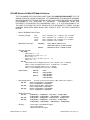
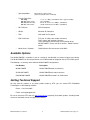
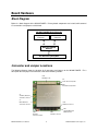
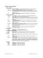
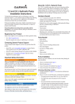
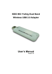
WLAN17202ER User's Manual
Embedded Wireless LAN 802.11a/b/g PC/104-Plus Module
BDM-610020036
Rev. B
ISO9001 and AS9100 Certified
WLAN17202ER User's Manual
RTD EMBEDDED TECHNOLOGIES, INC.
103 Innovation Blvd
State College, PA 16803-0906
Phone: +1-814-234-8087
FAX: +1-814-234-5218
E-mail
[email protected]
[email protected]
Web Site
http://www.rtd.com
WLAN17202ER User's Manual
1
RTD Embedded Technologies, Inc.
Manual Revision History
Rev A
Initial Release
Rev B
Updated jumper descriptions
Updated rotary switch settings table
Updated board picture
Added section to describe network activity LED
Published by:
RTD Embedded Technologies, Inc.
103 Innovation Boulevard
State College, PA 16803
Copyright 2005 by RTD Embedded Technologies, Inc.
All rights reserved
WLAN17202ER User's Manual
2
RTD Embedded Technologies, Inc.
The RTD Embedded Technologies Logo is a registered trademark of RTD Embedded Technologies.
dspModule, cpuModule, and utilityModule are trademarks of RTD Embedded Technologies. PC/104,
PC/104-Plus, and PCI-104 are registered trademark of PC/104 Consortium. Atheros is a trademark of
Atheros Communications. All other trademarks appearing in this document are the property of their
respective owners.
WLAN17202ER User's Manual
3
RTD Embedded Technologies, Inc.
Table of Contents
Introduction.................................................................................................................................................... 6
Product Overview ...................................................................................................................................... 6
Board Features .......................................................................................................................................... 6
PCI Interface ...................................................................................................................................... 6
Physical Attributes.............................................................................................................................. 6
5004 MP Atheros 4G Mini-PCI Module Features............................................................................... 7
Available Options....................................................................................................................................... 8
Getting Technical Support ......................................................................................................................... 8
Board Hardware ............................................................................................................................................ 9
Block Diagram ........................................................................................................................................... 9
Connector and Jumper Locations ............................................................................................................. 9
External I/O Connections......................................................................................................................... 10
Connector CN1/CN2 - PC/104 ISA...................................................................................................... 10
Connector CN3 - PC/104 PCI Bus....................................................................................................... 10
PCI Bus Signal Assignments ........................................................................................................... 10
PCI Bus Signal Description .............................................................................................................. 11
Connectors J3 and J4 – WLAN Antenna Connectors ......................................................................... 12
PCI Configuration Options....................................................................................................................... 12
Rotary Switch SW1 – PCI Slot Selector .............................................................................................. 12
Bus Master Control .............................................................................................................................. 12
Network Activity LED ........................................................................................................................... 13
Board Installation ........................................................................................................................................ 14
Installing the Hardware............................................................................................................................ 14
Static Precautions ................................................................................................................................ 14
Steps for Installing ............................................................................................................................... 14
Installing Software ................................................................................................................................... 15
Windows Drivers .................................................................................................................................. 15
Linux Drivers ........................................................................................................................................ 15
Additional Information ................................................................................................................................. 16
WLAN17202ER User's Manual
4
RTD Embedded Technologies, Inc.
5004 MP Atheros 4G Mini-PCI WLAN Module........................................................................................ 16
Atheros AR5004X Chipset....................................................................................................................... 16
IEEE 802.11 WLAN Specifications.......................................................................................................... 16
Limited Warranty ......................................................................................................................................... 17
WLAN17202ER User's Manual
5
RTD Embedded Technologies, Inc.
Introduction
Product Overview
The WLAN17202ER is designed to provide wireless communication for PC/104-Plus and PCI-104 based
systems. It communicates via the standard 802.11a/b/g protocols. The WLAN17202ER can be used to
connect multiple PC systems together. The WLAN17202ER uses the 5004 MP Atheros 4G Mini-PCI
module from Netgate. This module is connected to the PC/104 PCI bus through a Mini-PCI connector
and special circuitry to allow for compatibility with either 3.3V or 5V PCI signaling.
Board Features
o
o
o
o
o
o
o
PC/104 PCI and ISA stack through busses
5004 MP Atheros 4G Mini-PCI module
Atheros AR5004X Client Chipset
Supports IEEE 802.11a, 80211b, 802.11g protocols
Two MCX Jacks for dual antennas
Structural support system for the Mini-PCI module to increase ruggedness.
Needs only +5V input power
THE WLAN17202ER IS AN EMBEDDED MODULE WHICH IS INTENDENDED TO BE
INTEGRATED INTO A FINAL SYSTEM. IT PROVIDES POWER, ANTENNA ACCESS, AND
STRUCTURAL SUPPORT FOR RUGGED SYSTEMS. IT IS INCUMBENT ON THE USER TO
OBTAIN ANY CERTIFICATIONS WHICH MAY BE REQUIRED FOR OPERATION WHEN
INTEGRATED INTO ITS FINAL APPLICATION. THE ONLY CURRENT CERTIFICATIONS
WHICH MAY RELATE TO THIS MODULE ARE THE ONES WHICH HAVE BEEN OBTAINED
FOR THE 5004 MP ATHEROS 4G MINI-PCI MODULE FROM NETGATE.
PCI Interface
o
o
Supports 3.3V and 5.0V PCI Signaling
User-selectable PCI Slot Number
Physical Attributes
o
o
o
o
o
Size: 3.6”L x 3.8”W x 0.6”H (90mm L x 96mm W x 15mm H)
Weight: Approximately 0.18 lbs (0.08 Kg)
o
o
Operating Temperature:
0 C to +70 C
o
o
Storage Temperature:
-20 C to +80 C
Power Requirements @ +5 VDC:
FTP Tx :
FTP Rx :
Standby mode:
Power saving mode:
RF Kill :
WLAN17202ER User's Manual
802.11a
1.39 W
0.99 W
0.86 W
0.17 W
0.13 W
802.11b
1.43 W
1.02 W
0.83 W
0.17 W
0.13 W
6
802.11g
1.35 W
1.02 W
0.89 W
0.17 W
0.13 W
RTD Embedded Technologies, Inc.
5004 MP Atheros 4G Mini-PCI Module Features
THE FOLLOWING SPECIFICATIONS COME FROM THE NATEGATE DATASHEET FOR THE
5004 MP ATHEROS 4G MINI-PCI MODULE. RTD EMBEDEDED TECHNOLOGIES ASSUMES
NO RESPONSIBLILITY FOR ANY ERRORS IN THAT DATA SHEET AND DOES NOT ASSUME
RESPONSIBILITY FOR VERIFYING ITS ACCURACY.
INFORMATION FROM THIS
DATASHEET IS PROVIDED FOR CONVIENIENCE ONLY. IT IS THE RESPONSIBILITY OF
THE USER TO OPTAIN THE LATEST VERSION OF THE DATASHEET TO VERIFY THAT NO
CHANGES HAVE BEEN MADE WHICH MAY CONFLICT WITH THE DATA PRESENTED
BELOW.
o
Atheros AR5004X Client Chipset
o
Frequency Range:
o
Modulation Technique :
USA:
Europe:
Japan:
China:
2.400 – 2.483GHz, 5.15 ~ 5.35Ghz, 5.725 ~ 5.825Ghz
2.400 – 2.483GHz, 5.15 ~ 5.35Ghz, 5.47 ~ 5.725Ghz
2.400 – 2.483GHz, 4.90 - 5.091GHz, 5.15 – 5.25GHz
2.400 – 2.483GHz, 5.725 ~5.85Ghz
802.11b/g:
802.11a:
o
Channels Support:
o
Output Power :
802.11b/g:
US/Canada: 11 (1 ~ 11)
Major European country: 13 (1 ~ 13)
France: 4 (10 ~ 13)
Japan: 11b: 14 (1~13 or 14th), 11g: 13 (1 ~ 13)
China: 13 (1 ~ 13)
802.11a:
US/Canada:12 non-overlapping channels (5.15~ 5.35GHz, 5.725 ~ 5.825GHz)
Europe: 19 non-overlapping channel (5.15 ~ 5.35GHz, 5.47 ~ 5.725GHz)
Japan: 4 non-overlapping channels (5.15 ~ 5.25GHz)
China : 5 non-overlapping channels (5.725 ~ 5.85GHz)
802.11b:
802.11g:
802.11a:
o
802.11a:
802.11g:
Depends on Antenna performance, LOS, and the laws of physics
Outdoor: 85m@54Mbps, 300m@6Mbps
Indoor: 20m@54Mbps, 40m@6Mbps
Outdoor:300m@11Mbps, 400m@1Mbps
Indoor: 30m@11Mbps, 50m@1Mbps
Outdoor: 80m@54Mbps, 300m@6Mbps
Indoor: 15m@54Mbps, 35m@6Mbps
Receive Sensitivity:
802.11a:
802.11b:
802.11g:
o
18dBm
18dBm @6Mbps
15dBm @54Mbps
17dBm @6Mbps
13dBm @54Mbps
Operating distance:
802.11b:
o
DSSS (DBPSK, DQPSK, CCK)
OFDM (BPSK,QPSK, 16-QAM, 64-QAM)
OFDM(BPSK,QPSK, 16-QAM, 64-QAM)
Security:
WLAN17202ER User's Manual
-88dB@6Mbps, -87dB@9Mbps, -85@12Mbps, -83dB@18Mbps,
-80dB@24Mbps,-75dB@36Mbps, -73dB@48Mbps, -71dB@54Mbps
-95dB@1Mbps, -94dB@2Mbps, [email protected], -90dB@11Mbps
-90dB@6Mbps, -89dB@9Mbps, -87@12Mbps, -85dB@18Mbps,
-82dB@24Mbps,-79dB@36Mbps, -76dB@48Mbps, -74dB@54Mbps
- 64-bit,128-bit, 152-bit WEP Encryption
- 802.1x Authentication
- AES-CCM & TKIP Encryption
7
RTD Embedded Technologies, Inc.
o
Operating Modes:
o
Transfer Data Rate:
o
Wi-Fi Alliance:
WECA Compliant
o
WHQL:
Microsoft XP Compliant
o
FAA:
S/W audio On/Off support
o
EMC Certificate:
FCC part 15 (USA), with multiple e-Antenna
Telec (Japan), with multiple e-Antenna
These certifications do not imply the certification of the
WLAN17202ER. Please see not in Section: “Board Features”
above.
o
Media Access Protocol :
CSMA/CA with ACK architecture 32-bit MAC
Infrastructure & Ad-hoc mode
(depends upon OS, driver, and band)
11, 5.5, 2, 1 Mbps, auto-fallback, 802.11g up to 54 Mbps
Up to 108 Mbps
54, 48, 36, 24, 18, 12, 9, 6Mbps, autofallback
108,96,72,48,36,24,18,12 Mbps, autofallback
802.11b/g:
802.11g (Super mode):
802.11a (Normal mode):
802.11a (Turbo mode):
Available Options
The WLAN17202ER is available as part of a starter kit, bundled with an external antenna and cabling.
The WLAN17202ER can also be purchased as an IDAN module for integration into an RTD IDAN system.
The following is a summary of the different WLAN17202ER configurations:
Part Number
Description
WLAN17202ER
WLAN17202ER board (no antennas)
SK-WLAN17202ER
WLAN17202ER with external antenna
IDAN-WLAN17202ER
WLAN17202ER mounted in an IDAN frame
Getting Technical Support
For help with this product, or any other product made by RTD, you can contact RTD Embedded
Technologies via the following methods:
Phone: +1-814-234-8087
E-Mail: [email protected]
Be sure to check the RTD web site (http://www.rtd.com) frequently for product updates, including newer
versions of the board manual and application software.
WLAN17202ER User's Manual
8
RTD Embedded Technologies, Inc.
Board Hardware
Block Diagram
Below is a block diagram of the WLAN17202ER. Primary board components are in bold, while external
I/O connections and jumpers are italicized.
!"#
!$
Connector and Jumper Locations
The following diagram shows the location of all connectors and jumpers on the WLAN17202ER. For a
description of each jumper and connector, refer to the following sections.
CN1:
PCI Bus Conn.
D1:
Network Activity LED
JP1:
External Activity LED
J4:
Auxiliary External
Antenna Connector
J3:
Main External
Antenna Connector
CN1:
XT ISA Connector
CN2:
AT ISA Connector
SW1:
PCI Slot
Selection Switch
WLAN17202ER User's Manual
9
JP2:
Onboard/External
LED Selection
RTD Embedded Technologies, Inc.
External I/O Connections
The following sections describe the external I/O connections of the WLAN17202ER.
Connector CN1/CN2 - PC/104 ISA
Connector CN1/CN2 carries the signals of the PC/104-Plus ISA bus. The signals from this bus are not
used on this module. The connector serves as a pass-through to other PC/104 and PC/104-Plus
modules.
Connector CN3 - PC/104 PCI Bus
Connector CN3 carries the signals of the PC/104-Plus PCI bus. These signals match definitions of the
PCI Local Bus specification Revision 2.2. The following tables list the pinouts of the PC/104-Plus bus
connector.
PCI Bus Signal Assignments
Pin
1
2
3
4
5
6
7
8
9
10
11
12
13
14
15
16
17
18
19
20
21
22
23
24
25
26
27
28
29
30
A
GND
VI/O
AD05
C/BE0#
GND
AD11
AD14
+3.3V
SERR#
GND
STOP#
+3.3V
FRAME#
GND
AD18
AD21
+3.3V
IDSEL0
AD24
GND
AD29
+5V
REQ0#
GND
GNT1#
+5V
CLK2
GND
+12V
-12V
WLAN17202ER User's Manual
B
Reserved
AD02
GND
AD07
AD09
VI/O
AD13
C/BE1#
GND
PERR#
+3.3V
TRDY#
GND
AD16
+3.3V
AD20
AD23
GND
C/BE3#
AD26
+5V
AD30
GND
REQ2#
VI/O
CLK0
+5V
INTD#
INTA#
REQ3#
10
C
+5 AD00
AD01
AD04
GND
AD08
AD10
GND
AD15
Reserved
+3.3V
LOCK#
GND
IRDY#
+3.3V
AD17
GND
AD22
IDSEL1
VI/O
AD25
AD28
GND
REQ1#
+5V
GNT2#
GND
CLK3
+5V
INTB#
GNT3#
D
+5V
AD03
AD06
GND
M66EN
AD12
+3.3V
PAR
Reserved
GND
DEVSEL#
+3.3V
C/BE2#
GND
AD19
+3.3V
IDSEL2
IDSEL3
GND
AD27
AD31
VI/O
GNT0#
GND
CLK1
GND
RST#
INTC#
GND
RTD Embedded Technologies, Inc.
PCI Bus Signal Description
Address and Data
AD[31:00]
Address and Data are multiplexed on the same PCI pins. A bus transaction
consists of an address phase followed by one or more data phases.
C/BE[3:0]#
Bus Command/Byte Enables are multiplexed. During the address phase of a
transaction, they define the bus command. During the data phase, they are used
as byte enables.
PAR
Parity is even parity across AD[31:00] and C/BE[3:0]#. Parity generation is
required by all PCI signals.
Interface Control Pins
FRAME#
Cycle Frame is driven by the current master to indicate the beginning of an
access and will remain active until the final data cycle.
TRDY#
Target Ready indicates the selected device’s ability to complete the current data
phase of the transaction. Both IRDY# and TRDY# must be asserted to terminate a
data cycle.
IRDY#
Initiator Ready indicates the bus master's ability to complete the current data
phase of the transaction.
STOP#
Stop indicates the current selected device is requesting the master to stop the
current transaction.
DEVSEL#
Device Select, when actively driven, indicates the driving device has decoded its
address as the target of the current access.
IDSEL
Initialization Device Select is used as a chip-select during configuration read
and write transactions.
LOCK#
Lock indicates an atomic operation to a bridge that may require multiple
transactions to complete.
Error Reporting
PERR#
Parity Error is for reporting data parity errors.
SERR#
System Error is for reporting address parity errors.
Arbitration (Bus Masters Only)
REQ#
Request indicates to the arbitrator that this device desires use of the bus.
GNT#
Grant indicates to the requesting device that access has been granted.
System
CLK
Clock provides timing for all transactions on the PCI bus and is an input to every
PCI device.
RST#
Reset is used to bring PCI-specific registers, sequencers, and signals to a
consistent state.
M66EN
66 MHz Enable indicates to a device whether the bus segment is operating at 33
MHz or 66 MHz. The PCI bus has been simulated at 33MHz. For the purpose of
this specification, 66MHz is not supported. To support future enhancements, the
M66EN signal should be grounded on any module that cannot support 66MHz and
left open for modules that can support a 66MHz clock.
Interrupts
INTA#
Interrupt A is used to request Interrupts.
INTB#
Interrupt B is used to request Interrupts.
INTC#
Interrupt C is used to request Interrupts.
INTD#
Interrupt D is used to request Interrupts.
WLAN17202ER User's Manual
11
RTD Embedded Technologies, Inc.
Connectors J3 and J4 – WLAN Antenna Connectors
WLAN17202ER is capable of hardware antenna diversity if external antennas are connected to both of
the on-board Main and Auxiliary antenna connectors. These connectors are of the MCX/OSX type.
External WLAN antennas are available as part of the SK-WLAN17202ER starter kit.
Note:
The WLAN17202ER will automatically use whichever antenna has the greatest signal strength. If
only one antenna is attached, that one will always be used.
PCI Configuration Options
To install the WLAN17202ER into the stack, the PCI Slot Number must be configured correctly. This is
done by the rotary switch SW1. There are four possible PCI Slot Numbers (0 – 3). Each PCI device
(PC/104-Plus or PCI-104) must a use a different slot number. The slot number is related to the position of
the board in the stack. Slot 0 represents the PCI device closest to the CPU. Slot 3 represents the PCI
devices farthest away from the CPU.
Note:
In a PC/104-Plus or PCI-104 system, all PCI devices should be located on one side of the CPU
board (above or below the add-on cards). The CPU should not be located between two PCI
devices.
Rotary Switch SW1 – PCI Slot Selector
The WLAN17202ER has an eight position rotary switch which supports both 3 and 4 bus master
configurations. The PCI Slot Number can be configured as follows:
Switch Position
0
1
2
3
4
5
6
7
PCI Slot Number
Slot 0 (closest to CPU)
Slot 1
Slot 2
Slot 3
Slot 0
Slot 1
Slot 2
Slot 2
Bus Master
4 bus master
configuration
3 bus master
configuration
Bus Master Control
When the PC/104-Plus Specification was first introduced, it only allowed for three PCI add-on cards to be
bus masters. Version 2.0 of the PC/104-Plus specification was released in November 2003. This version
of the specification (which the WLAN17202ER is designed for) adds support for all 4 PCI slots to be bus
masters.
For compatibility with CPUs designed for the older PC/104-Plus Specification, the WLAN17202ER offers
several rotary switch settings. If the rotary switch is set in positions 0 through 3, the board supports bus
mastering in all 4 PCI slots. If the rotary switch is set to positions 4 through 7, the board will work in a 3
bus master configuration.
WLAN17202ER User's Manual
12
RTD Embedded Technologies, Inc.
Network Activity LED
A network activity LED (D1) may be enabled by setting jumper JP2 to pins 1-2 (default configuration).
When JP2 is configured to pins 2-3, an external activity LED connector (JP1) is enabled.
When configured to use an external LED, the onboard activity LED (D1) will be disabled.
following table to connect an external LED to jumper JP1:
Use the
External LED Connection (JP1)
Pin
Function
1
Cathode
2
Anode
Note:
Pin 1 is indicated by a square solder pad on the bottom side of the board.
WLAN17202ER User's Manual
13
RTD Embedded Technologies, Inc.
Board Installation
Installing the Hardware
The WLAN17202ER can be installed into a PC/104-Plus or PCI-104 stack. It can be located above or
below the CPU, as long as all PCI add-on cards are on the same side of the CPU.
Static Precautions
Keep your board in its antistatic bag until you are ready to install it into your system! When removing it
from the bag, hold the board at the edges and do not touch the components or connectors. Handle the
board in an antistatic environment and use a grounded workbench for testing and handling of your
hardware.
Steps for Installing
1. Shut down the PC/104-Plus system and unplug the power cord.
2. Ground yourself with an anti-static strap.
3. Set the PCI Slot Selector as described in the previous chapter.
4. If any other PCI add-on cards are to be included in the stack, be sure that their PCI slot numbers
are configured correctly (Slot 0 for the board closest to the CPU, Slot 1 for the next board, etc).
5. Line up the pins of the WLAN17202ER’s PC/104 and PC/104-Plus connectors with the
corresponding bus connectors of the stack. Make sure that both connectors are lined up.
6. Apply pressure to both bus connectors and gently press the board onto the stack. The board
should slide into the matching bus connectors. Do not attempt to force the board, as this can
lead to bent/broken pins.
7. Attach the Main WLAN antenna to connector J3.
8. If using an Auxiliary WLAN antenna, attach it to connector J4.
9. If any boards are to be stacked above the WLAN17202ER, install them.
10. Attach any necessary cables to the PC/104-Plus stack.
11. Re-connect the power cord and apply power to the stack.
12. Boot the system and verify that all of the hardware is working properly.
Note:
If multiple PCI devices are configured to use the same PCI slot number, the system will not boot.
WLAN17202ER User's Manual
14
RTD Embedded Technologies, Inc.
Installing Software
After physically installing the WLAN17202ER, your operating system must be configured to recognize the
new board.
Windows Drivers
Windows drivers should be included on CD-ROM with the WLAN17202ER. Installation instructions
should be provided in the file README.TXT. Follows these instructions to install and configure the
software.
Note:
Before installing any drivers, it is recommended that you visit the RTD web site
(http://www.rtd.com) to check for a newer version.
Linux Drivers
Linux software support is provided by the “madwifi” open source project. For installation instructions and
technical support, visit http://www.madwifi.org.
WLAN17202ER User's Manual
15
RTD Embedded Technologies, Inc.
Additional Information
5004 MP Atheros 4G Mini-PCI WLAN Module
For detailed information about the 5004 MP Atheros 4G Mini-PCI WLAN module, Netgate at:
Web:
http://www.netgate.com
Atheros AR5004X Chipset
For detailed information about the Atheros AR5004X chipset, contact Atheros at:
Web:
http://www.atheros.com
IEEE 802.11 WLAN Specifications
A copy of the 802.11 WLAN specifications can be downloaded from the IEEE web site at:
Web:
http://www.ieee.org
WLAN17202ER User's Manual
16
RTD Embedded Technologies, Inc.
Limited Warranty
RTD Embedded Technologies, Inc. warrants the hardware and software products it manufactures and
produces to be free from defects in materials and workmanship for one year following the date of shipment from RTD EMBEDDED TECHNOLOGIES, INC. This warranty is limited to the original purchaser of
product and is not transferable.
During the one year warranty period, RTD EMBEDDED TECHNOLOGIES will repair or replace, at its option, any defective products or parts at no additional charge, provided that the product is returned,
shipping prepaid, to RTD EMBEDDED TECHNOLOGIES. All replaced parts and products become the
property of RTD EMBEDDED TECHNOLOGIES. Before returning any product for repair, customers are
required to contact the factory for an RMA number.
THIS LIMITED WARRANTY DOES NOT EXTEND TO ANY PRODUCTS WHICH HAVE BEEN
DAMAGED AS A RESULT OF ACCIDENT, MISUSE, ABUSE (such as: use of incorrect input voltages,
improper or insufficient ventilation, failure to follow the operating instructions that are provided by RTD
EMBEDDED TECHNOLOGIES, "acts of God" or other contingencies beyond the control of RTD
EMBEDDED TECHNOLOGIES), OR AS A RESULT OF SERVICE OR MODIFICATION BY ANYONE
OTHER THAN RTD EMBEDDED TECHNOLOGIES. EXCEPT AS EXPRESSLY SET FORTH ABOVE,
NO OTHER WARRANTIES ARE EXPRESSED OR IMPLIED, INCLUDING, BUT NOT LIMITED TO, ANY
IMPLIED WARRANTIES OF MERCHANTABILITY AND FITNESS FOR A PARTICULAR PURPOSE,
AND RTD EMBEDDED TECHNOLOGIES EXPRESSLY DISCLAIMS ALL WARRANTIES NOT STATED
HEREIN. ALL IMPLIED WARRANTIES, INCLUDING IMPLIED WARRANTIES FOR MECHANTABILITY
AND FITNESS FOR A PARTICULAR PURPOSE, ARE LIMITED TO THE DURATION OF THIS
WARRANTY. IN THE EVENT THE PRODUCT IS NOT FREE FROM DEFECTS AS WARRANTED
ABOVE, THE PURCHASER'S SOLE REMEDY SHALL BE REPAIR OR REPLACEMENT AS PROVIDED
ABOVE. UNDER NO CIRCUMSTANCES WILL RTD EMBEDDED TECHNOLOGIES BE LIABLE TO THE
PURCHASER OR ANY USER FOR ANY DAMAGES, INCLUDING ANY INCIDENTAL OR
CONSEQUENTIAL DAMAGES, EXPENSES, LOST PROFITS, LOST SAVINGS, OR OTHER DAMAGES
ARISING OUT OF THE USE OR INABILITY TO USE THE PRODUCT.
SOME STATES DO NOT ALLOW THE EXCLUSION OR LIMITATION OF INCIDENTAL OR
CONSEQUENTIAL DAMAGES FOR CONSUMER PRODUCTS AND SOME STATES DO NOT ALLOW
LIMITATIONS ON HOW LONG AN IMPLIED WARRANTY LASTS, SO THE ABOVE LIMITATIONS OR
EXCLUSIONS MAY NOT APPLY TO YOU.
THIS WARRANTY GIVES YOU SPECIFIC LEGAL RIGHTS, AND YOU MAY ALSO HAVE OTHER
RIGHTS WHICH VARY FROM STATE TO STATE.
WLAN17202ER User's Manual
17
RTD Embedded Technologies, Inc.