1
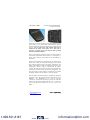
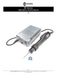
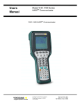
M1 Series - DM
Instruction Manual 9R000034-IR
E.O. 6409 JAN 2008
M1 SERIES – DIGITAL MANOMETER
USER MANUAL
Meriam Process Technologies’ M1 Series pressure instrument
is a microcontroller-based pressure sensing device that can be
used to directly measure pressure. Differential, Gauge and
Absolute pressure sensors are supported up to 100 PSI.
Pressure can be displayed in selectable engineering units of
PSI, bar, mbar, kPa, mmHg, inHg, mmH2O or inH2O.
www.meriam.com
Page 1 of 17
1.800.561.8187
www.
.com
[email protected]
M1 Series - DM
Instruction Manual 9R000034-IR
E.O. 6409 JAN 2008
Table of Contents
Introduction ...............................................................3
User Interface..........................................................4
Single Keypad Functions ...........................................4
ON/OFF (O) Key....................................................4
BACKLIGHT (B) Key ...........................................4
FUNC (F) Key ........................................................4
UNIT (U) Key.........................................................4
Zeroing the M1 ..........................................................5
Functional Modes ......................................................5
Liquid Crystal Display (LCD) ................................6
Engineering Units Select ........................................7
Record Mode ..........................................................8
Auto Shut-Off .........................................................9
Field Recalibration ..................................................10
ZERO....................................................................10
SPAN ....................................................................11
Restore Factory Defaults ......................................11
Specifications ..........................................................12
Certification/Safety/Warnings .................................14
Changing the Batteries.............................................14
User Connections.....................................................16
Contact Information.................................................17
www.meriam.com
Page 2 of 17
1.800.561.8187
www.
.com
[email protected]
M1 Series - DM
Instruction Manual 9R000034-IR
E.O. 6409 JAN 2008
Introduction
Thank you for purchasing this Meriam product. Meriam has been
providing innovative, reliable, cost-effective measurement and
calibration solutions since 1911.
The M1 has been designed using the latest technology to provide
reliable accuracy throughout its entire operating temperature range,
dependable operation, and exceptional battery life.
The compact design makes the unit easy to carry and the intuitive
user interface makes it easy to use.
Pressure measurements are displayed on a large, easy-to-read
liquid crystal display (LCD). This unit has two backlights: a green
backlight which is user activated, and an automatic red backlight
which indicates an error/over-range condition.
Four keys provide direct access to frequently used functions (like
Units, Backlight). Other, less frequently used functions (like Zero,
Span, and Record) are accessible via multiple key combinations. A
complete list of these functions is printed on the back of the case.
www.meriam.com
Page 3 of 17
1.800.561.8187
www.
.com
[email protected]
M1 Series - DM
Instruction Manual 9R000034-IR
E.O. 6409 JAN 2008
User Interface
Single Keypad Functions
ON/OFF (O) Key
The ON/OFF key, represented by the standard ON/OFF symbol,
turns the M1 ON or OFF (note: the ON/OFF key must be held until
the display turns on or off). Upon power on, the M1 will perform a
self test, display all segments for approximately 1-2 seconds, then
go into the normal pressure measure mode using the last pressure
units selected.
To view the calibrated accuracy and firmware revision, press and
hold the ON/OFF key for approximately 2 seconds upon power on.
The display will alternate between the calibrated accuracy and
firmware revision for as long as the ON/OFF key is held.
BACKLIGHT (B) Key
The BACKLIGHT key, represented by the standard light-bulb
symbol, turns the green display backlight on and off. The backlight
will remain on for approximately 20 seconds if not manually
turned off. To temporarily override the auto shut off feature, press
and hold the BACKLIGHT key for approximately 2 seconds (until
the backlight turns on-off-on).
FUNC (F) Key
This key selects the functional mode of the M1. Detailed
instructions are provided on the back of the unit and in the
subsequent sections.
UNIT (U) Key
This key selects the engineering unit of measure desired when the
M1 is in NORMAL or TEMP mode.
www.meriam.com
Page 4 of 17
1.800.561.8187
www.
.com
[email protected]
M1 Series - DM
1.
Instruction Manual 9R000034-IR
E.O. 6409 JAN 2008
Zeroing the M1
To Zero the M1, first turn off pressure sources and vent pressure
ports to atmosphere. Then simultaneously press and hold the F
and U keys until “F.CAL” is displayed. The display will read “---” during the zeroing process. The process is complete when the
display changes from “----” to a “zero” reading.
Note: The M1 can only be zeroed if the measured zero is within
±2.5% (of FS) of the factory calibrated zero limit. Further
details are provided under Field Recalibration.
2.
Functional Modes
The Digital Manometer supports NORMAL and TEMP modes.
The NORMAL mode of operation has an additional sub-mode
referred to as “REC” or record mode, which is described later.
For Pressure measurements:
The red backlight will illuminate when the M1 is measuring
pressure values outside its calibrated range. When the red backlight
is on, the accuracy of these measurements is uncharacterized.
Beyond 110% of the calibrated range, “----” will be displayed. The
red backlight will be illuminated in both cases.
The minimum and maximum pressure the M1 has measured is
permanently recorded for factory warranty issues.
For Temperature measurements:
• Selecting the TEMP mode (the °F or °C icon) will display the
internal ambient temperature of the M1.
o the UNIT key will toggle between °F and °C
The minimum and maximum temperature the M1 has
measured is permanently recorded for factory warranty issues.
www.meriam.com
Page 5 of 17
1.800.561.8187
www.
.com
[email protected]
M1 Series - DM
Instruction Manual 9R000034-IR
E.O. 6409 JAN 2008
Liquid Crystal Display (LCD)
The LCD displays the:
• Pressure or Temperature measurement via large digits,
• Pressure measurement via bar graph, and
• Pressure or Temperature engineering units via icons.
A low battery warning (the BAT icon) is displayed when the
batteries require replacement. Approximately 2 hours of run time
is available immediately following a low battery warning.
The bar graph at the bottom of the display always shows a reading
of the currently applied pressure as a percent of the full scale of the
M1.
The LCD incorporates two backlights:
• a green backlight which is user activated via the BACKLIGHT
key, and
• a red backlight which is automatically activated during an
error/over-range condition
During an error or over-range condition, the red backlight will
“over-ride” the green backlight. However, once the error or overrange condition is corrected, the green backlight will be restored to
its previous state (if the backlight auto-off timer did not expire).
The backlight should be turned off when not needed to conserve
battery power. The backlight feature will be reduced when the M1
is in low battery mode.
www.meriam.com
Page 6 of 17
1.800.561.8187
www.
.com
[email protected]
M1 Series - DM
Instruction Manual 9R000034-IR
E.O. 6409 JAN 2008
Engineering Units Select
For pressure measurements:
mmHg
inHg
mmH2O
inH2O
kPa
mbar
bar
PSI
user 1
user 2
(@ 0°C)
(@ 0°C)
(@ 20°C)
(@ 20°C)
(optional)
(optional)
To change the pressure units, press the UNIT key while in
NORMAL mode.
“user 1” and “user 2” are reserved for custom user defined “units
of measure”. Contact Meriam if this support is required.
Notes: Depending upon the pressure range of the M1, some
engineering units may not be available (i.e. they will be
skipped).
When the M1 is turned on, it will default to the last
selected pressure engineering units.
For temperature measurements:
°F
°C
To change the temperature units, press the UNIT key while in
TEMP mode.
Notes: When the TEMP mode is selected, the M1 will default to
the last selected temperature engineering units.
www.meriam.com
Page 7 of 17
1.800.561.8187
www.
.com
[email protected]
M1 Series - DM
Instruction Manual 9R000034-IR
E.O. 6409 JAN 2008
Record Mode
The M1 can store up to 240 pressure measurements (also called
values or points) in a single record (REC) session. For maximum
flexibility, a REC session can be:
• Automatic - the current value is automatically stored every 5
seconds, for up to 20 minutes
• Manual - the current value is stored every time the U key is
pressed, up to 240 times
Both types of REC sessions can store between 1 and 240
measurements. The measurement data is preserved in non-volatile
memory until another REC session is started.
REC Data:
In NORMAL mode enter REC Data mode by pressing both the B
and F keys until the REC icon begins flashing.
Second, choose the type of REC session.
To start an automatic REC session, press the F key. This will
delete the previously stored pressure measurement and store the
current pressure measurement. Then, every 5 seconds, the current
pressure value will be stored.
To start a manual REC session, press the U key. This will delete
the previously stored session and store the current pressure
measurement. Then, every time the U key is pressed, the current
pressure value will be stored.
For both types of REC session, the pressure value on the LCD will
blank briefly every time a sample is stored, and after 240
measurements have been recorded, the following step (stop and
exit REC Data mode) will happen automatically.
Third, to stop and exit REC Data mode, press both the B and F
keys. All previously stored REC session data will be saved and the
M1 will return to NORMAL mode (the REC icon will go off). This
step can be done anytime the REC icon is flashing.
www.meriam.com
Page 8 of 17
1.800.561.8187
www.
.com
[email protected]
M1 Series - DM
Instruction Manual 9R000034-IR
E.O. 6409 JAN 2008
REC View:
First, set the M1 to NORMAL mode (no functional mode icons on).
Then enter REC View mode by pressing both the B and U keys
until the REC icon illuminates.
Second, press the U key to cycle through the stored values. The
pressure value on the LCD will blank briefly every time a sample
is displayed, and after all the recorded samples have been viewed,
“----” will be displayed and the following step (stop and exit REC
View mode) will happen automatically.
Third, to stop and exit REC View mode, press both the B and U
keys. The M1 will return to NORMAL mode (the REC icon will
go off). This step can be done anytime the REC icon is on.
Auto Shut-Off
To conserve battery life, the M1 will automatically power off after
30 minutes of keypad inactivity.
www.meriam.com
Page 9 of 17
1.800.561.8187
www.
.com
[email protected]
M1 Series - DM
Instruction Manual 9R000034-IR
E.O. 6409 JAN 2008
Field Recalibration
The M1 can be recalibrated in the field for zero and span. The
proper primary standards must be available prior to calibrating the
unit. These standards should meet the accuracy requirements for
your company or industry. Meriam Process Technologies follows
the guidelines established by ANSI/NCSL Z540 which requires
that the primary standard be 4 times more accurate than the unit
under test.
The field recalibration is not intended to replace the Factory
calibration procedure. It is intended to trim the factory calibration
curve fit to accommodate slight changes in sensor characteristics
over time.
ZERO
To Zero the M1, first turn off pressure sources and vent pressure
ports to atmosphere. Then simultaneously press and hold the F
and U keys until “F.CAL” is displayed. The process is complete
when the display changes from “----” to a “zero” reading.
Note: The M1 can only be zeroed if the measured zero is within
±2.5% (of FS) of the factory calibrated zero.
At this point, the M1 can be zeroed.
The above process applies only to gauge and differential
pressure instruments. To recalibrate the zero on an absolute
pressure instrument, the applied pressure must be within 10
times the full scale accuracy term of the original factory
calibrated zero. 200 microns is Meriam’s standard vacuum
reference for all absolute pressure sensors.
Note: It should be noted that if the zero reference source used to
recalibrate any pressure instrument is not accurate, the M1
zero can be recalibrated to a maximum discrepancy of
2.5% of the original factory zero. This can create a 2.5%
offset in all pressure measurements after the recalibration
of zero.
If this procedure generates a new value outside this limit,
the red backlight will flash to indicate the procedure failed
and the previous value was retained.
www.meriam.com
Page 10 of 17
1.800.561.8187
www.
.com
[email protected]
M1 Series - DM
Instruction Manual 9R000034-IR
E.O. 6409 JAN 2008
SPAN
First, before the M1 can be spanned, it must be zeroed.
Second, to Span the M1, a calibration specific pressure must be
applied. If this Span pressure is known (because the unit has been
spanned previously), skip the next step.
To determine the Span pressure, make sure the pressure sources
are still vented (i.e. still at zero), then press and hold the O and B
keys until “F.CAL” is displayed. Immediately following “F.CAL”
is the value of the pressure that should be applied. The red
backlight will flash to indicate the M1 was not spanned (since
there was no pressure applied).
Third, apply the Span pressure to the M1 and let the pressure
stabilize. Then press and hold the O and B keys until “F.CAL” is
displayed. Immediately following “F.CAL” is the value of the
pressure that should be applied. The display will read “----” during
the spanning process. The process is complete when the display
changes from “----” to the Span pressure reading.
Note: The M1 can only be spanned if the calculated measured
span is within 5 times full scale accuracy of the original
factory calibrated span pressure.
For example, given:
Accuracy = 0.25% FS, FS = 100 PSI, and Span = 70 PSI
the Measured Span must be within ±1.25 PSI of 70 PSI
Note: It should be noted that if the span pressure source used to
recalibrate any pressure instrument is not accurate, the M1
span can be recalibrated to a maximum discrepancy of
1.25% of the original factory span calibration pressure.
This can create a 1.25% gain error in all pressure
measurements after the recalibration of span.
If this procedure generates a new value outside this limit,
the red backlight will flash to indicate the procedure failed
and the previous value was retained.
Restore Factory Defaults
The factory calibration defaults can be restored in the M1 by
simultaneously pressing the O and F and U keys until the display
shows “----”. The process is complete when the display changes
from “----” to the current pressure reading.
www.meriam.com
Page 11 of 17
1.800.561.8187
www.
.com
[email protected]
M1 Series - DM
Instruction Manual 9R000034-IR
E.O. 6409 JAN 2008
Specifications
Type and Range:
All sensors are non-isolated
D – 28 inH2O (1 psi)
D – 138 inH2O (5 psi)
D – 416 inH2O (15 psi)
D – 832 inH2O (30 psi)
D – 2000 inH2O (72.3 psi)
A – 755 mmHg (15 psia)
A – 1551 mmHg (30 psia)
A – 2585 mmHg (50 psia)
G – 5 psi
G – 15 psi
G – 30 psi
G – 50 psi
G – 100 psi
Accuracy:
±0.25% of FS
Includes the combined effects of temperature, linearity,
repeatability, hysteresis and resolution.
Temperature:
Storage = -40°C to +60°C (-40°F to +140°F)
Operating = -10°C to +50°C (14°F to +122°F)
Reading = Inside product @ ±1°C
Media Compatibility:
Clean, dry, non-corrosive gases only.
Pressure Limits:
D – 3 × FS range on high side only or 200 PSI, whichever is
less
G or A – 3 × FS range or 200 PSI, whichever is less
Connection:
D – 1/8” female NPT, 316SS. P1 = high side, P2 = low side
G – 1/8” female NPT, P1 port only, P2 vent
A – 1/8” female NPT, P1 port only, P2 vent
See User Connection Section of this Manual
www.meriam.com
Page 12 of 17
1.800.561.8187
www.
.com
[email protected]
M1 Series - DM
Instruction Manual 9R000034-IR
E.O. 6409 JAN 2008
Battery Type:
3 x AA battery, field replaceable.
Alkaline (A900614-00011):
Duracell, PC1500, 1.5V, 2000mAh
Duracell, MN1500, 1.5V, 2000mAh
Varta, 4906, 1.5V, 2600mAh
Battery Operation:
> 300 hours continuous use without backlight on, 1 year
shelf life, auto power off set at 30 minutes, low battery
warning giving approximately 2 hours of run time.
Enclosure:
(6.5” × 3.2” × 1.1”) Polycarbonate, Permanently Static
Dissipative, ESD Protection
Enclosure with Boot: (6.8” × 3.5” × 1.3”)
Display Resolution:
Range 0-9
0-99 0-999 0-9999
Display x.yyy xx.yy xxx.y xxxx
Some pressure units may display differently depending upon
full scale range and accuracy.
Display Warnings
° HI = The temperature of M1 above valid calibration
range/field recalibration value.
° LO = The temperature of M1 below valid calibration
range/field recalibration value.
P HI = Pressure applied to M1 above valid calibration
range/field recalibration value.
P LO = Pressure applied to M1 below valid calibration
range/field recalibration value.
www.meriam.com
Page 13 of 17
1.800.561.8187
www.
.com
[email protected]
M1 Series - DM
Instruction Manual 9R000034-IR
E.O. 6409 JAN 2008
Certification/Safety/Warnings
The following defines the certification and area classification of
the M1 Series pressure instrument.
Note the following WARNINGS and requirements:
•
User must use bulkhead fitting hex surface when attaching
user’s 1/8” NPT fitting.
When making mechanical
connections DO NOT apply torque to bulkhead fitting that
causes the fitting to turn or twist with respect to plastic
enclosure. To do so, will damage the product and void the
warranty.
Changing the Batteries
The M1 is powered by three, 1.5 volt AA size batteries. When the
output of the batteries drop below a normal level, the display will
activate the “BAT” icon, indicating a low battery condition. A low
battery condition may affect performance and therefore, the unit
should not be used to measure pressure. All three batteries should
be replaced.
To replace the battery locate the battery compartment in the bottom
rear of the M1, as shown below.
www.meriam.com
Page 14 of 17
1.800.561.8187
www.
.com
[email protected]
M1 Series - DM
Instruction Manual 9R000034-IR
E.O. 6409 JAN 2008
Remove the two screws located at the top center and bottom center
of the battery cover by turning them counterclockwise until the
fully disengaged from the M1 base. Lift the cover from the back of
the unit. Do not remove the pink antistatic foam that is
attached to the inside of the battery cover. This foam is
necessary to properly secure the batteries under specified
shock and vibration conditions!
Remove the batteries by pulling the positive side first straight out
of the battery compartment. Note the positive (+) and negative (-)
battery polarity markings at the bottom of the compartment, as
shown here.
Install the three batteries by sliding them into the bottom of the
battery slots, making sure the polarity markings on the batteries
align with the markings shown in the battery compartment. The
battery compartment has stand offs molded into the side of the
compartment. When a battery is installed with the polarity
reversed, the stand offs prevent the negative battery terminal from
contacting the positive terminal in the battery compartment. The
unit will not power up when a battery is installed this way. Should
this happen, simply reverse the battery to correct the polarity.
With the batteries secured in the battery compartment, replace the
compartment cover. The cover has only one orientation for correct
alignment. The “WARNING DO NOT OPEN IN EXPLOSIVE
ATMOSPHERE” statement on the battery cover must be visible and
aligned in the approximate middle of the M1 case. To secure the
cover, torque the screws clockwise to 1.6 in-lbs. Do not over
tighten.
www.meriam.com
Page 15 of 17
1.800.561.8187
www.
.com
[email protected]
M1 Series - DM
Instruction Manual 9R000034-IR
E.O. 6409 JAN 2008
User Connections
Connection: 1/8” female NPT, 316SS. The pressure connections
(P1 and P2) are marked on top of the keypad as shown on page 1.
“D” or Differential models have 2 used pressure ports. P1 is the
high pressure connection and P2 is the low pressure connection (as
shown below).
“G” Gauge and “A” Absolute models have one used pressure port,
P1. P2 is used to vent enclosure/sensor to atmosphere.
Absolute
Pressure
Differential
A
+
Gauge
Barometric Pressure
or
Atmospheric Pressure
Vacuum
B
Absolute Zero
WARNING Connection to the incorrect pressure port may
cause damage to the pressure sensor. Once this sort of damage
occurs, the unit must be returned to the factory for sensor
replacement.
WARNING User must use bulkhead fitting hex surface when
attaching user’s 1/8” NPT fitting. No torque can be applied to
bulkhead fitting with respect to plastic enclosure.
www.meriam.com
Page 16 of 17
1.800.561.8187
www.
.com
[email protected]
M1 Series - DM
Instruction Manual 9R000034-IR
E.O. 6409 JAN 2008
Contact Information
If the M1 cannot be zeroed, spanned, or is damaged, it must be
returned to the factory for servicing. In this case, contact the
Meriam Process Technologies representative in your area or call
the factory at the numbers listed below for a Return Material
Authorization (RMA) number.
Meriam Process Technologies
10920 Madison Ave.
Cleveland, OH 44102
Phone (216) 281-1100 FAX (216) 281-0228
All M1 Series pressure instruments recalibrated at the factory are
returned with certificates of NIST traceability.
www.meriam.com
Page 17 of 17
1.800.561.8187
www.
.com
[email protected]