1
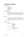
Snapshot
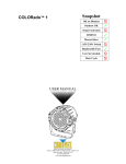
COLORado™ 1
OK on Dimmer
Outdoor OK
Sound Activated
DMX512
Master/Slave
115V/230V Switch
Replaceable Fuse
User Serviceable
Duty Cycle
USER MANUAL
Chauvet, 3000 N 29th Ct, Hollywood, FL 33020 U.S.A.
(800) 762-1084 – (954) 929-1115
FAX (954) 929-5560
www.chauvetlighting.com
TABLE OF CONTENTS
1. BEFORE YOU BEGIN....................................................................................................................................................... 3
WHAT IS INCLUDED .............................................................................................................................................................. 3
UNPACKING INSTRUCTIONS .................................................................................................................................................. 3
AC POWER ......................................................................................................................................................................... 3
CONTACT US ...................................................................................................................................................................... 3
SAFETY INSTRUCTIONS ........................................................................................................................................................ 4
2. INTRODUCTION ............................................................................................................................................................... 5
FEATURES .......................................................................................................................................................................... 5
DMX CHANNEL SUMMARY ................................................................................................................................................... 5
PRODUCT OVERVIEW .......................................................................................................................................................... 6
3. SETUP ............................................................................................................................................................................... 7
FUSE REPLACEMENT ........................................................................................................................................................... 7
FIXTURE LINKING ................................................................................................................................................................. 7
Data Cabling ................................................................................................................................................................. 7
DMX Data Cable.................................................................................................................................................... 7
Cable Connectors .................................................................................................................................................. 8
3-Pin to 5-Pin Conversion Chart ............................................................................................................................ 8
SETTING UP A DMX SERIAL DATA LINK ................................................................................................................................ 8
MASTER/SLAVE FIXTURE LINKING ........................................................................................................................................ 9
MOUNTING .......................................................................................................................................................................... 9
Orientation ............................................................................................................................................................. 9
Rigging................................................................................................................................................................... 9
4. OPERATING INSTRUCTIONS........................................................................................................................................ 10
NAVIGATING THE CONTROL PANEL ..................................................................................................................................... 10
MENU MAP........................................................................................................................................................................ 11
MENU FUNCTIONS ............................................................................................................................................................. 12
User Configurations .................................................................................................................................................... 12
Programming Custom Scenes............................................................................................................................. 12
Upload custom programs to another fixture: ....................................................................................................... 12
Activate or Deactivate the password: .................................................................................................................. 13
Service Functions ....................................................................................................................................................... 13
Reset custom programs to factory defaults ......................................................................................................... 13
OPERATION ....................................................................................................................................................................... 13
Stand-Alone Mode (Auto Mode): ................................................................................................................................ 13
Master/Slave Mode (Master Sound, Master Auto):..................................................................................................... 13
DMX Mode .................................................................................................................................................................. 14
DMX-512 control without “ID” address........................................................................................................................ 14
DMX-512 addressing with ID address ........................................................................................................................ 14
EXAMPLE CONFIGURATIONSDMX CHANNEL VALUES .......................................................................................................... 15
DMX CHANNEL VALUES .................................................................................................................................................... 16
5. COLORADO™ CONTROLLER ...................................................................................................................................... 18
OVERVIEW ........................................................................................................................................................................ 18
SETUP .............................................................................................................................................................................. 18
MENU MAP........................................................................................................................................................................ 19
Wash Program ............................................................................................................................................................ 19
Effect Program ............................................................................................................................................................ 19
Custom Program......................................................................................................................................................... 20
Play Schedule ............................................................................................................................................................. 20
Clock ........................................................................................................................................................................... 20
Schedule ..................................................................................................................................................................... 20
Settings ....................................................................................................................................................................... 20
Activating password mode .......................................................................................................................................... 21
Control via external DMX ............................................................................................................................................ 21
GENERAL TROUBLESHOOTING ........................................................................................................................................... 23
TECHNICAL SUPPORT ........................................................................................................................................................ 23
6. APPENDIX....................................................................................................................................................................... 24
DMX PRIMER .................................................................................................................................................................... 24
PHOTOMETRICS ................................................................................................................................................................ 25
GENERAL MAINTENANCE ................................................................................................................................................... 25
GENERAL MAINTENANCE ................................................................................................................................................... 26
RETURNS PROCEDURE ...................................................................................................................................................... 26
CLAIMS ............................................................................................................................................................................. 26
TECHNICAL SPECIFICATIONS .............................................................................................................................................. 27
COLORado 1 User Manual
2
2007-05-18/12:46
1. BEFORE YOU BEGIN
What is included
¾
¾
¾
¾
¾
¾
¾
¾
1 x COLORado™ 1
1 x Power cable with plug
1 x IP65 power extension cable
1 x IP65 signal extension cable
1 x DMX input cable
1 x DMX output cable
Warranty Card
Users Manual
Unpacking Instructions
Immediately upon receiving a fixture, carefully unpack the carton, check the contents to ensure that
all parts are present, and have been received in good condition. Notify the shipper immediately and
retain packing material for inspection if any parts appear damaged from shipping or the carton itself
shows signs of mishandling. Save the carton and all packing materials. In the event that a fixture
must be returned to the factory, it is important that the fixture be returned in the original factory box
and packing.
AC Power
This fixture has an auto-switching power supply that can accommodate a wide range of input
voltages. The only thing necessary to do before powering on the unit is to make sure the line voltage
you are applying is within the range of accepted voltages. This fixture will accommodate between
100V and 240V AC. All fixtures must be powered directly off a switched circuit and cannot be run off a
rheostat (variable resistor) or dimmer circuit, even if the rheostat or dimmer channel is used solely for
a 0% to 100% switch.
Contact Us
World Wide
General Information
Chauvet Lighting
th
3000 North 29 Court
Hollywood, FL 33020
voice: 954.929.1115
fax:
954.929.5560
toll free: 800.762.1084
Technical Support
Chauvet Lighting
th
3000 North 29 Court
Hollywood, FL 33020
voice: 954.929.1115 (Press 4)
fax:
954.929.5560 (Attention: Service)
World Wide Web
www.chauvetlighting.com
COLORado 1 User Manual
3
2007-05-18/12:46
Safety Instructions
Please read these instructions carefully, which includes important
information about the installation, usage and maintenance of this
product.
•
•
•
•
•
•
•
•
•
•
•
•
Caution!
Please keep this User Guide for future consultation. If you sell the unit to another user, be sure that
they also receive this instruction booklet.
Always make sure that you are connecting to the proper voltage, and that the line voltage you are
connecting to is not higher than that stated on the decal or rear panel of the fixture.
Make sure there are no flammable materials close to the unit while operating.
Always disconnect from power source before servicing or replacing fuse and be sure to replace with
same fuse source.
Secure fixture to fastening device using a safety chain.
Maximum ambient temperature (Ta) is 95°F (35°C). Do not operate fixture at temperatures higher
than this.
In the event of a serious operating problem, stop using the unit immediately. Never try to repair the
unit by yourself. Repairs carried out by unskilled people can lead to damage or malfunction. Please
contact the nearest authorized technical assistance center. Always use the same type spare parts.
Don’t connect the device to a dimmer pack.
Make sure the power cord is never crimped or damaged.
Never disconnect the power cord by pulling or tugging on the cord.
Avoid direct eye exposure to the light source while it is on.
Do not daisy chain power to more than 20 units at 120V, or 40 units at 230V.
There are no user serviceable parts inside the unit. Do not open the housing or
attempt any repairs yourself. In the unlikely event your unit may require service,
please contact CHAUVET at: 954-929-1115.
COLORado 1 User Manual
4
2007-05-18/12:46
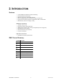
2. INTRODUCTION
Features
•
•
•
•
•
•
9-channel DMX-512 LED PAR can (with ID addressing)
Blackout/static/dimmer/strobe/pulse
RGB color mixing with or without DMX controller
Built-in automated programs via master/slave, DMX or COLOR-CON
Program and recall custom programs via master/slave, DMX or COLOR-CON
RGB fade delay channel for snapping or fading
Ad d i t i o n a l F e a t u r e s
•
•
•
•
•
•
Available in black or silver
Durable and weather resistant IP65 rated
Additional power output for daisy chaining units together (max 20 units @ 120V)
LED display with lock-out feature
Gel frame holder (4mm max thickness)
Low power consumption
Optional Controller
•
COLORado™ Controller (COLOR-CON)
DMX Channel Summary
CHANNEL FUNCTION
1
Master Dimmer
2
Red
3
Green
4
Blue
5
Color Macros
6
Strobe
7
Auto/Custom Programs
8
9
ID Address
COLORado 1 User Manual
Instant/Delayed Color Change
5
2007-05-18/12:46
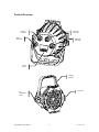
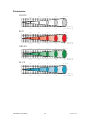
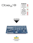
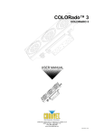
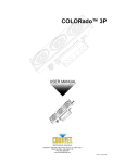
Product Overview
Power In
Connector
Power Out
Connector
DMX In
Connector
DMX Out
Connector
Control
Panel
Hanging
Bracket
Gel frame
Tilt
Adjustment
Knob
COLORado 1 User Manual
6
2007-05-18/12:46
3. SETUP
Disconnect the power cord before replacing a fuse and always
replace with the same type fuse.
Fuse Replacement
The fuse for this fixture is located inside the chassis. Remove the damaged fuse from its holder and
replace with exact same type fuse. Reconnect power.
Fixture Linking
You will need a serial data link to run light shows of one or more fixtures using a DMX-512 controller
or to run synchronized shows on two or more fixtures set to a master/slave operating mode. The
combined number of channels required by all the fixtures on a serial data link determines the number
of fixtures the data link can support.
Important:
Fixtures on a serial data link must be daisy chained in one single line. To
comply with the EIA-485 standard no more than 32 devices should be connected on
one data link. Connecting more than 32 fixtures on one serial data link without the
use of a DMX optically-isolated splitter may result in deterioration of the digital DMX
signal.
Maximum recommended serial data link distance: 500 meters (1640 ft.)
Maximum recommended number of fixtures on a serial data link: 32 fixtures
Data Cabling
To link fixtures together you must obtain data cables. You can purchase CHAUVET-certified DMX
cables directly from a dealer/distributor or construct your own cable. If you choose to create your own
cable please use data-grade cables that can carry a high quality signal and are less prone to
electromagnetic interference.
D MX DA TA CAB LE
Use a Belden© 9841 or equivalent cable which meets the specifications for EIA RS-485 applications.
Standard microphone cables cannot transmit DMX data reliably over long distances. The cable will
have the following characteristics:
2-conductor twisted pair plus a shield
Maximum capacitance between conductors – 30 pF/ft.
Maximum capacitance between conductor and shield – 55 pF/ft.
Maximum resistance of 20 ohms / 1000 ft.
Nominal impedance 100 – 140 ohms
COLORado 1 User Manual
7
2007-05-18/12:46
CAB LE C ONN ECTORS
Cabling must have a male XLR connector on one end and a female XLR connector on the other end.
1
3
2
DMX connector configuration
COMMON
1
3
INPUT
2
CAUTION
1
3
2
DMX +
DMX
-
Resistance 120
ohm 1/4w between
pin 2 (DMX -) and
pin 3 (DMX +) of
the last fixture.
OUTPUT
Termination reduces signal errors. To
avoid signal transmission problems
and interference, it is always
advisable to connect a DMX signal
terminator.
Do not allow contact between the common and the fixture’s chassis
ground. Grounding the common can cause a ground loop, and your fixture may
perform erratically. Test cables with an ohm meter to verify correct polarity and to
make sure the pins are not grounded or shorted to the shield or each other.
3-PIN TO 5- PIN CO N VER SION CHAR T
Note!
If you use a controller with a 5 pin DMX output connector, you will need to use a 5
pin to 3 pin adapter. CHAUVET Model No: DMX5M, or DMX5F.
The chart below details a proper cable conversion:
3 PIN TO 5 PIN CONVERSION CHART
Conductor
3 Pin Female (output)
5 Pin Male (Input)
Ground/Shield
Pin 1
Pin 1
Data ( - ) signal
Pin 2
Pin 2
Data ( + ) signal
Pin 3
Pin 3
Do not use
Do not use
Do not use
Do not use
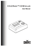
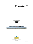
Universal DMX Controller
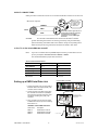
Setting up a DMX Serial Data Link
1. Connect the (male) 3 pin connector side of
the DMX cable to the output (female) 3 pin
connector of the controller.
2. Connect the end of the cable coming from
the controller which will have a (female) 3
pin connector to the input connector of the
next fixture consisting of a (male) 3 pin
connector.
This drawing provides a
general illustration of the
DMX Input/Output panel of
a lighting fixture.
3. Then, proceed to connect from the output
as stated above to the input of the following
fixture and so on.
CHAUVET Certified DMX Data Cables
Order Code
Description
DMX1.5
DMX Cable 1.5m/4.9ft
DMX4.5
DMX Cable 4.5m/14.8ft
DMX10
DMX Cable 10m/32.8ft
COLORado 1 User Manual
8
Continue the link
2007-05-18/12:46
Master/Slave Fixture Linking
1. Connect the (male) 3 pin connector side of the DMX cable to the output (female) 3 pin connector
of the first fixture.
2. Connect the end of the cable coming from the first fixture which will have a (female) 3 pin
connector to the input connector of the next fixture consisting of a (male) 3 pin connector. Then,
proceed to connect from the output as stated above to the input of the following fixture and so on.
Often, the setup for Master-Slave
and Standalone operation requires
that the first fixture in the chain be
initialized for this purpose via either
settings in the control panel or DIPswitches. Secondarily, the fixtures
that follow may also require a slave
setting. Please consult the
“Operating Instructions” section in
this manual for complete instructions
for this type of setup and
configuration.
Mounting
ORIENTATION
This fixture may be mounted in any position provided there is adequate room for ventilation.
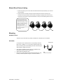
R IG G IN G
Hanging Clamp
It is important never to obstruct the fan or vents pathway. Mount the
fixture using, a suitable “C” or “O” type clamp. Adjust the angle of the
fixture by loosening both knobs and tilting the fixture. After finding the
desired position, retighten both knobs.
•
•
•
When selecting installation location, take into consideration lamp
replacement access and routine maintenance.
Safety cables must always be used.
Never mount in places where the fixture will be exposed to rain, high
humidity, extreme temperature changes or restricted ventilation.
COLORado 1 User Manual
9
Note!
Clamp is sold separately.
2007-05-18/12:46
4. OPERATING INSTRUCTIONS
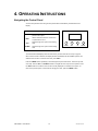
Navigating the Control Panel
Access control panel functions using the four panel buttons located directly underneath the LCD
Display.
Button
Function
<MENU>
Used to access the menu or to return to a
previous menu option
<SET>
Used to select and store the current menu
or option within a menu
<UP>
Scrolls through menu options in ascending
order
<DOWN>
Scrolls through menu options in descending
order
MENU
SET
UP
DOWN
The Control Panel LED Display shows the menu items you select from the menu map on page #.
When a menu function is selected, the display will show immediately the first available option for the
selected menu function. To select a menu item, press <SET>.
Press the <MENU> button repeatedly to scroll through the top level menu items. This is the top of the
menu map. Use the <UP> and <DOWN> buttons to navigate the menu map and menu options. Press
the <SET> button to access the menu function currently displayed or to enable a menu option. To
return to the previous option or menu without changing the value, press the <MENU> button.
COLORado 1 User Manual
10
2007-05-18/12:46
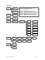
Menu Map
AUTO
AT.01 – AT.10
(Automatic 1-10)
PR.C1 - PR.10
(Custom 1-10)
dMX
Id
Edit
SET
d001 – d500
When navigating the menu:
Use the “UP” button to move up.
Use the “DOWN” button to move down.
Use the “SET” button to move right.
Use the “MENU” button to move left.
I001 – I066
(ID Address)
PR.C1 – PR.10
SC.01 – SC.30
(Custom 1-10)
(Scene 1-30)
rEd
R.000 – R.255
GrEn
G.000 – G.255
bluE
b.000 – b.255
Strb
S.000 – S.255
TIME
T.000 – T.255
FAdE
F.000 – F.255
UPLd
PASS
****
Send
REST
PASS
****
rEST
PASS
End
ON
OFF
COLORado 1 User Manual
11
2007-05-18/12:46
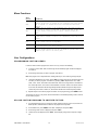
Menu Functions
MENU
OPTION
DESCRIPTION
Auto Mode – Master Unit: Sets the fixture to Master status for Master-Slave
operation and the built in programs will be triggered by the sound. No data
link is required; all fixtures can be set to this mode for Stand-alone
operation.
DMX Mode: Sets the fixture to run in DMX mode. Also, this mode is used to
set a fixture to operate in Slave mode. In Master/Slave mode you must set
the first fixture in the data link to “Master” otherwise nothing will
happen.
ID Address: Sets the ID address of the fixture, which allows up to 3,696 (66
per DMX address) COLORado 1 fixtures to be independently controlled on one
universe.
AUTO
dMX
Id
Edit
Used to create and edit custom programs. Up to 10 custom programs with up to
30 steps (scenes) each can be programmed.
SET
Used to upload the custom programs from one fixture to another, and to reset
the custom programs to the factory defaults.
PASS
Turns the password protection on or off. If turned on, you must enter a
password to gain access to the control panel.
User Configurations
PROGRA MM IN G CU ST OM SC ENES
In order to create a custom program than can be run in any mode, do the following:
1)
In the menu, select “Edit”. Next, scroll through until the desired program number is displayed,
and select it.
2)
Scroll through to the step you wish to program, and select it.
Note: The program runs in sequential order, starting with step 01, and continuing through step 30.
3)
“rEd” will be displayed on the screen. Press <SET> to edit the value for red. Scroll through to the
red value you wish to program, and select it by pressing <SET>. Repeat this for the, “GrEn”,
“bluE”, “Strb”, “TimE”, and “FAdE” values. Note that “TimE” is the length of time in minutes that
the current step will run, and must be a value between 0 and 255. “Fade” is the amount of time,
in seconds, that the fixture will take to gradually transition between the previous step and the
current step. If the value of “Fade” is 0, the transition will be at the maximum speed possible.
4)
Repeat steps 2 and 3 until the program is created. To end programming, press <MENU> twice.
The program can be run in any mode. See the instructions for the desired operating mode in order to
run the custom program.
U PLOAD CU STOM PROGRAMS TO ANOTHER FIXTUR E:
1)
On all fixtures that are going to receive the custom programs from the source unit, set them for
DMX operation; address does not matter for the purpose of this operation.
2)
On the Master unit, press <MENU> until “SET” is displayed, and press <SET>.
3)
Scroll through until “UPLd” is displayed, and press <SET>.
4)
“PASS” will now be displayed. Press <SET>, and the display will go blank, except for a single
dot.
COLORado 1 User Manual
12
2007-05-18/12:46
5)
Press <UP>, then <DOWN>, then <UP>, then <DOWN>, then <SET>. This is the same
password that is used for the main access password.
6)
“SENd” will now be displayed, and all units will output the color yellow.
7)
When the upload is complete, the sending fixture will display “ENd”, and all fixtures will output
the color green to indicate a successful upload. If a unit has an error, it will output the color red.
8)
Press <MENU> on the source unit to exit the upload mode.
ACTIVA TE OR DEACTIVATE THE PASSWORD:
1)
Press <MENU> until “PASS” is displayed, and press <SET>.
2)
Select “OFF” or “ON” and press <SET>.
Note:
The password is permanently set as <UP>, <DOWN>, <UP>, <DOWN>; this cannot be
changed.
Service Functions
RESET CUSTOM PROGRAMS TO FACTORY DEFAULTS
1)
Press <MENU> until “SET” is displayed, and press <SET>.
2)
Scroll through until “REST” is displayed, and press <SET>.
3)
“PASS” will now be displayed. Press <SET>, and the display will go blank, except for a single
dot.
4)
Press <UP>, then <DOWN>, then <UP>, then <DOWN>, then <SET>. This is the same
password that is used for the main access password.
5)
“REST” will now be displayed, and will be flickering. After about 30 seconds, the reset sequence
will be complete, and “REST” will be displayed without flickering.
6)
Press <MENU> to exit the reset mode.
Operation
Stand-Alone Mode (Auto Mode):
This mode allows a single unit to auto change in Auto Mode.
1)
Press <MENU> until “Auto” appears on the display, and press <SET>.
2)
Press scroll through to the desired program (either Auto 1-10 or Custom 1-10), and press <SET>
to select it. The unit will now auto change in Auto Mode.
Master/Slave Mode (Master Sound, Master Auto):
This mode will allow you to link up to 32 units together without a controller.
1)
Use standard DMX cables to daisy chain your units together via the DMX connector on the rear
of the units. For longer cable runs we suggest a terminator at the last fixture. For more
information about terminators, see page 8.
2)
Choose a unit to function as the Master. The unit must be the first unit in line. Press <MENU>
until “Auto” appears on the display, and press <SET>.
3)
Press scroll through to the desired program (either Auto 1-10 or Custom 1-10), and press <SET>
to select it.
4)
Then simply chain the units together using DMX cable.
5)
On the Slave units, press <MENU> until “dMX” is displayed and press <SET>.
COLORado 1 User Manual
13
2007-05-18/12:46
DMX Mode
This mode allows the unit to be controlled by any universal DMX controller. If you are unfamiliar with
DMX, please read the DMX Primer on page 24.
1)
Press <MENU> until “dMX” is displayed and press <SET>.
2)
Scroll through to select the desired address, and press <SET>.
DMX-512 control without “ID” address
The COLORado™ 1 operates on 9 channels of DMX. Address each fixture in increments of 9
channels. (I.e. 1, 10, 19, 28 etc…) To save time you can use the same DMX address for each fixture.
All fixtures will then respond simultaneously to control. You may also group your fixtures and address
those groups alike for faster programming and control.
1)
Press <MENU> until “dMX” is displayed and press <SET>.
2)
Scroll through to select the desired address, and press <SET>.
Note:
This fixture always has an ID address; it cannot be deactivated. Unintended results
may occur if values are present in channel 8. Make sure values on channel 8 are set
to “0”.
DMX-512 addressing with ID address
1)
Press <MENU> until “dMX” is displayed and press <SET>.
2)
Scroll through to select the desired DMX address, and press <SET>.
3)
Press <MENU> until “Id” is displayed and press <SET>.
4)
Scroll through to select the desired ID address, and press <SET>. For every DMX512 starting
address the user can set 66 separate ID addresses.
Note:
COLORado 1 User Manual
ID addresses are accessible using Channel 8.
14
2007-05-18/12:46
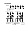
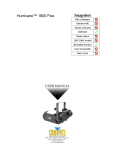
Example Configurations
Single Row
Application
ID Address: 01
ID Address: 02
ID Address: 03
ID Address: 05
ID Address: 04
ID Address: 06
The figure above shows 6 fixtures connected in series with corresponding
addresses. You must set the {Range} settings in the controller to [006] before
accessing {Effect} programs.
SET
UP
DOWN
EXIT
Repeat Row Block Application
ID Address: 01
ID Address: 02
ID Address: 01
ID Address: 02
ID Address: 01
ID Address: 02
Block Application
ID Address: 03
ID Address: 03
ID Address: 03
COLORado 1 User Manual
UP
ID Address: 02
ID Address: 04
ID Address: 05
ID Address: 07
The figure above shows 9 fixtures connected
in series. Three rows comprised of 3 fixtures
are addressed identically. You must set the
{Range} settings in the controller to [003]
before accessing {Effect} programs.
SET
ID Address: 01
DOWN
EXIT
15
ID Address: 08
The figure above shows 9 fixtures
connected in series with
corresponding addresses. You must
set the {Range} settings in the
controller to [009] before accessing
{Effect} programs.
ID Address: 03
ID Address: 06
ID Address: 09
SET
UP
DOWN
EXIT
2007-05-18/12:46
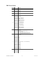
DMX Channel Values
CHANNEL VALUE
FUNCTION
1
000 Ù 255
Master Dimmer: 0 – 100%
2
000 Ù 255
Red (or step time when PR. 01 – PR. 10 is activated)
0 – 100%
3
000 Ù 255
Green (or fade time when PR. 01 – PR. 10 is activated)
0 – 100%
4
000 Ù 255
Blue
0 – 100%
5
000 Ù 009
010 Ù 029
030 Ù 039
040 Ù 049
050 Ù 069
070 Ù 079
080 Ù 089
090 Ù 109
110 Ù 119
120 Ù 129
130 Ù 149
150 Ù 159
160 Ù 169
170 Ù 189
190 Ù 199
200 Ù 219
220 Ù 229
230 Ù 239
240 Ù 255
Color Macros
No function
Red
Red 85%, Yellow 15%
Red 60%, Yellow 40%
Yellow
Yellow 85%, Green 15%
Yellow 60%, Green 40%
Green
Green 85%, Blue 15%
Green 60%, Blue 40%
Blue
Blue 85%, Cyan 15%
Blue 60%, Cyan 40%
Cyan
Cyan 50%, Purple 50%
Purple
Purple 50%, White 50%
White 95%, Yellow 5%
White
6
000 Ù 009
010 Ù 063
064 Ù 127
128 Ù 191
192 Ù 255
Strobe
No function
Strobe with pulse effect (slow > fast)
Strobe (slow > fast)
Color changing pulse with fadeout (slow > fast)
Color changing pulse with fade-in/out (slow > fast)
7
000 Ù 009
010 Ù 019
020 Ù 029
030 Ù 039
040 Ù 049
050 Ù 059
060 Ù 069
070 Ù 079
080 Ù 089
090 Ù 099
100 Ù 109
110 Ù 119
120 Ù 129
130 Ù 139
140 Ù 149
150 Ù 159
160 Ù 169
170 Ù 179
180 Ù 189
190 Ù 199
200 Ù 255
Programs
No function
Auto 1
Auto 2
Auto 3
Auto 4
Auto 5
Auto 6
Auto 7
Auto 8
Auto 9
Auto 10 (Cycle Auto 1 – 9 for 5 minutes each)
Custom 1
Custom 2
Custom 3
Custom 4
Custom 5
Custom 6
Custom 7
Custom 8
Custom 9
Custom 10
8
000 Ù 009
010 Ù 019
020 Ù 029
030 Ù 039
ID Address
All IDs
ID 1
ID 2
ID 3
COLORado 1 User Manual
16
2007-05-18/12:46
040 Ù 049
050 Ù 059
060 Ù 069
070 Ù 079
080 Ù 089
090 Ù 099
100 Ù 109
110 Ù 119
120 Ù 129
130 Ù 139
140 Ù 149
150 Ù 159
160 Ù 169
170 Ù 179
180 Ù 189
190 Ù 199
200 Ù 209
210
211
212
213
214
215
216
217
218
219
220
221
222
223
224
225
226
227
228
229
230
231
232
233
234
235
236
237
238
239
240
241
242
243
244
245
246
247
248
249
250
251
252
253
254
255
9
COLORado 1 User Manual
ID 4
ID 5
ID 6
ID 7
ID 8
ID 9
ID 10
ID 11
ID 12
ID 13
ID 14
ID 15
ID 16
ID 17
ID 18
ID 19
ID 20
ID 21
ID 22
ID 23
ID 24
ID 25
ID 26
ID 27
ID 28
ID 29
ID 30
ID 31
ID 32
ID 33
ID 34
ID 35
ID 36
ID 37
ID 38
ID 39
ID 40
ID 41
ID 42
ID 43
ID 44
ID 45
ID 46
ID 47
ID 48
ID 49
ID 50
ID 51
ID 52
ID 53
ID 54
ID 55
ID 56
ID 57
ID 58
ID 59
ID 60
ID 61
ID 62
ID 63
ID 64
ID 65
ID 66
RGB Fader Response
Instant (snap)
5 second fade
000 Ù 250
251 Ù 255
17
2007-05-18/12:46
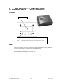
5. COLORADO™ CONTROLLER
Overview
LCD Display Panel
MODE
SETUP
UP
DOWN
MODE
Accesses main menu or backs out of sub-menu
SETUP
Selects the currently displayed menu or confirms the current function value
UP
Use to navigate upwards through menu items or increment function values
DOWN
Use to navigate downwards through menu items or decrement function values
Setup
Connect from the OUT on the controller to the DMX Input side of the COLORado™ 1 using a DMX XLR
cable. It is recommended that you power up all COLORado units connected prior to turning on the
controller. This ensures that the controller will auto-detect DMX addresses.
Alternatively you can use {Detect device} from the {Settings} menu.
Set ID addresses on the COLORado’s in ascending order.
Set the {Range} in the {Settings} menu.
Note
COLORado 1 User Manual
There is no need to set ID and Range for {Wash} programs.
18
2007-05-18/12:46
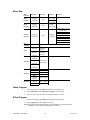
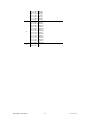
Menu Map
MAIN
FUNCTION
SELECTION
SELECTION
SELECTION
Wash
program
Wash [1]
Ù
Wash [8]
Edit
Step time
[001] Ù [255]
Fade time
[001] Ù [255]
Effect
program
Effect [1]
Ù
Effect [8]
Edit
Speed
[001] Ù [100]
Custom
program
Custom [1]
Ù
Custom [8]
Play
schedule
Schedule
Time now
Clock
Edit time
Schedule
Settings
Password
Edit
Scene [1]
Ù
Scene [100]
SELECTION
ID address [000*] Ù [100]
(*0 = all units)
Step time [000] Ù [255]
Fade time [000] Ù [255]
Red [000] Ù [255]
Green [000] Ù [255]
Blue [000] Ù [255]
Module [001] Ù [006]
Strobe [000] Ù [020]
I.e.
12/31/2006
13:50:24
I.e.
12/31/2006
13:50:24
Wash [1]
Ù
Wash [8]
Effect [1]
Start>>>End
Ù
00:00>>00:00
Effect [8]
Custom [1]
Ù
Custom [8]
DMX address [001] Ù [255]
Range
[001] Ù [066]
Allow edit
[YES] Ù [NO]
Detect device
>>>
Reset to
[YES] Ù [NO]
Factory
settings
Password
[ON] Ù [OFF]
ON/OFF
Set password
[
]
Wash Program
1)
Select from the eight existing [Wash] programs and it will instantly play.
2)
Set the [Step time] and the [Fade time] in the [Edit] function if desired.
3)
The unit of time is 5 seconds and it can be adjusted between 1 and 255.
Effect Program
1)
Select from the eight existing [Effect] programs and it will instantly play.
2)
Vary the [Speed] of the effect between 1 and 255.
Note: effect programs were designed primarily for the COLORado 3. They will work with the
COLORado 1, but they may react differently from time to time.
COLORado 1 User Manual
19
2007-05-18/12:46
Custom Program
1)
Select from the eight existing [Custom] programs and it will instantly play.
2)
Enter the [Edit] section to create or edit program.
3)
You can create or edit up to 100 scenes. To omit a scene from execution set its [Step time] to
0.
4)
Select the ID address of the target unit. Setting ID address to 0 selects all units in the serial
link. Color/Effects combination for different IDs is allowed.
5)
Specify the [Module] or modules to run active.
Note: this option is intended for use with the COLORado 3; for the COLORado 1, it is
recommended that [Module] be set to zero. Setting it to any number other than zero may
cause unintended results.
0 = 1,2,3
1=1
2=2
3=3
4 = 1,2
5 = 2,3
6 = 1,3
6)
RGB mix using the [Red], [Green] and [Blue] functions and adjusting the range between 0 and
255.
7)
Select a [Strobe] speed from 0-20Hz if desired.
8)
Select the [Step time] for the current scene.
Step time unit values
Range 0 – 10 =
0.1sec per unit
Range 11 – 255 =
1 sec per unit
9)
Set a [Fade time] for the current scene in one second increments from 0 to 255.
Play Schedule
Simply activate this menu [Play schedule] to run.
Clock
[Clock] Â [Time now]: To view the current time on the controller.
[Clock] Â [Edit now]: Edit the time and date.
Schedule
There are 24 Wash, Effect and Custom programs that can be set with Start and End times. Start
times take priority over End times. Programs will not overlap. Programs with the most recent Start
time will always override the existing previously executed program.
Settings
[DMX address]
This function sets the DMX address for the controller. It is addressable from 1 to 250.
[Range]
Enter the number of fixtures connected in series.
[Allow edit]
This function either enables or disables editing in Wash, Effect and Custom programs.
[Detect device]
This is the manual method of detecting and connecting the controller to all new units in series. It is
COLORado 1 User Manual
20
2007-05-18/12:46
generally used when you add more units to an existing system. Turning off and then on the controller
has the same effect.
[Reset to factory settings]
This function will reset all the settings to the factory defaults except for [Custom] programs.
Factory Default Settings
Setting
Default
[Schedule]
[Wash program]
[Effect program]
[DMX address]
[Range]
[Allow edit]
[Password ON/OFF]
[Set password]
All times in schedule are reset to [00:00]
Step times and fade times are reset to [001]
Speeds are reset to [001]
DMX address is reset to [001]
Range is reset to [066]
Reset to [Yes]
Password is reset to [OFF]
Password is reset to [00000000] Down=0, Up=1
Activating password mode
1)
Set [Password] function to [ON]. This will prompt the user for a password every time the
controller is powered on.
2)
Toggle to [Set password] function in order to change the password.
3)
Input an 8 digit password using the [UP] & [DOWN] keys. Press the [SET] button to confirm.
Note
In the event that the user forgets the password use the following factory password
override:
[UP] Â [DOWN] Â [UP] Â [DOWN] Â [UP] Â [UP] Â [DOWN] Â [DOWN]
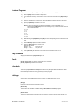
Control via external DMX
Programs in the controller can be accessed via an external DMX controller. It will be necessary to
have the DMX address set on the COLORado Controller. The controller operates on 4 channels of
control.
DMX Channel Values
CHANNEL
1
2
COLORado 1 User Manual
VALUE
FUNCTION
000 Ù 010
011 Ù 030
031 Ù 040
041 Ù 060
061 Ù 070
071 Ù 090
091 Ù 100
101 Ù 120
121 Ù 130
131 Ù 150
151 Ù 160
161 Ù 180
181 Ù 190
191 Ù 210
211 Ù 220
221 Ù 255
000 Ù 010
011 Ù 030
031 Ù 040
041 Ù 060
061 Ù 070
071 Ù 090
091 Ù 100
101 Ù 120
121 Ù 130
Blackout
Wash [1]
Blackout
Wash [2]
Blackout
Wash [3]
Blackout
Wash [4]
Blackout
Wash [5]
Blackout
Wash [6]
Blackout
Wash [7]
Blackout
Wash [8]
Blackout
Effect [1]
Blackout
Effect [2]
Blackout
Effect [3]
Blackout
Effect [4]
Blackout
21
2007-05-18/12:46
3
4
COLORado 1 User Manual
131 Ù 150
151 Ù 160
161 Ù 180
181 Ù 190
191 Ù 210
211 Ù 220
221 Ù 255
000 Ù 010
011 Ù 030
031 Ù 040
041 Ù 060
061 Ù 070
071 Ù 090
091 Ù 100
101 Ù 120
121 Ù 130
131 Ù 150
151 Ù 160
161 Ù 180
181 Ù 190
191 Ù 210
211 Ù 220
221 Ù 255
000 Ù 127
128 Ù 255
Effect [5]
Blackout
Effect [6]
Blackout
Effect [7]
Blackout
Effect [8]
Blackout
Custom [1]
Blackout
Custom [2]
Blackout
Custom [3]
Blackout
Custom [4]
Blackout
Custom [5]
Blackout
Custom [6]
Blackout
Custom [7]
Blackout
Custom [8]
OFF
ON
22
2007-05-18/12:46
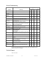
General Troubleshooting
Applies to
Symptom
Solution(s)
Lights
Auto shut off
Check fan thermal switch reset
9
Beam is very dim or
not bright
Clean optical system or check dimmer value
9
Breaker/Fuse keeps
blowing
Check total load placed on device
Chase is too slow
Check users manual for speed adjustment
9
Device has no power
Check for power on Mains.
Check device’s fuse. (internal and/or external)
9
Fixture is not
responding
Check DMX menu settings for correct addressing
Check DMX cables
Check polarity switch settings on controller
9
Fixture is on but
there is no
movement to the
audio
Make sure you have the correct audio mode on the
control switches. If audio provided via ¼” jack, make
sure a live audio signal exists
Adjust sound sensitivity knob
9
Lamps cut off
sporadically
Possible bad lamp or fixture is overheating.
Check DMX and power cable connections
9
Light will not come
on after power failure
Check fuse
Check for power on Mains
9
Loss of signal
Use only DMX cables
Install terminator
Note: Keep DMX cables separated from power cables
or black lights.
9
Moves slow
Check 220/110v switch for proper setting
9
No flash
Check correct DMX values
9
No laser output
Bounce mirror motor may have shifted during shipping,
readjust
9
No light output
Check slip ring & brushes for contact
Check correct DMX values or mode settings
Call service technician
9
Relay will not work
Check reset switch
Check cable connections
Remote does not
work
Make sure connector is firmly connected to device
9
Stand alone mode
Check user manual for proper stand alone mode
settings
9
Foggers
& Snow
Controllers
Dimmers
& Chaser
9
9
9
9
9
9
9
9
9
9
9
9
9
If you still have a problem after trying the above solutions, please contact CHAUVET Technical
Support at the location on the next page.
Technical Support
Address: Service Dept.
COLORado 1 User Manual
23
2007-05-18/12:46
3000 N 29th Ct, Hollywood, FL 33020 (U.S.A.)
Support (Email): [email protected]
Telephone: (954) 929-1115 - (Press 4)
Fax: (954) 929-5560 - (Attention: Service)
Website: http://www.chauvetlighting.com
6. APPENDIX
DMX Primer
There are 512 channels in a DMX-512 connection. Channels may be assigned in any manner. A
fixture capable of receiving DMX 512 will require one or a number of sequential channels. The user
must assign a starting address on the fixture that indicates the first channel reserved in the controller.
There are many different types of DMX controllable fixtures and they all may vary in the total number
of channels required. Choosing a start address should be planned in advance. Channels should
never overlap. If they do, this will result in erratic operation of the fixtures whose starting address is
set incorrectly. You can however, control multiple fixtures of the same type using the same starting
address as long as the intended result is that of unison movement or operation. In other words, the
fixtures will be slaved together and all respond exactly the same.
DMX fixtures are designed to receive data through a serial Daisy Chain. A Daisy Chain connection is
where the DATA OUT of one fixture connects to the DATA IN of the next fixture. The order in which
the fixtures are connected is not important and has no effect on how a controller communicates to
each fixture. Use an order that provides for the easiest and most direct cabling. Connect fixtures
using shielded two conductor twisted pair cable with three pin XLR male to female connectors. The
shield connection is pin 1, while pin 2 is Data Negative (S-) and pin 3 is Data positive (S+). CHAUVET
carries 3-pin XLR DMX compliant cables, DMX-10 (33’), DMX-4.5 (15’) and DMX-1.5 (5’)
COLORado 1 User Manual
24
2007-05-18/12:46
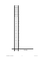
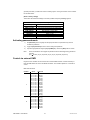
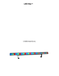
Photometrics
W H I TE
275 0
70 0
32 0
19 0
2
0.52
4
1.05
6
1.57
8
2.10
114 5
29 0
13 0
72
2
0.52
4
1.05
6
1.57
8
2.10
176 3
57 0
27 0
15 8
2
0.52
4
1.05
6
1.57
8
2.10
30 7
98
46
27
2
0.52
4
1.05
6
1.57
8
2.10
14 5
LU X
15
3
2
1
0
1
2
3
10
2.60
Dis t a n c e ( m)
Dia m e t e r ( m)
R ED
50
LU X
15
3
2
1
0
1
2
3
10
2.60
Di s ta n c e ( m)
Di a m e te r ( m)
G R E EN
12 8
LU X
15
3
2
1
0
1
2
3
10
2.60
Dis t a n c e ( m)
Dia m e t e r ( m)
B L UE
COLORado 1 User Manual
22
LU X
15
3
2
1
0
1
2
3
25
10
2.60
Di s t a n c e ( m)
Dia me t e r ( m)
2007-05-18/12:46
General Maintenance
To maintain optimum performance and minimize wear fixtures should be cleaned frequently. Usage
and environment are contributing factors in determining frequency. As a general rule, fixtures should
be cleaned at least twice a month. Dust build up reduces light output performance and can cause
overheating. This can lead to reduced lamp life and increased mechanical wear. Be sure to power off
fixture before conducting maintenance.
Unplug fixture from power. Use a vacuum or air compressor and a soft brush to remove dust
collected on external vents and internal components. Clean all glass when the fixture is cold with a
mild solution of glass cleaner or Isopropyl Alcohol and a soft lint free cotton cloth or lens tissue. Apply
solution to the cloth or tissue and drag dirt and grime to the outside of the lens. Gently polish optical
surfaces until they are free of haze and lint.
The cleaning of internal and external optical lenses and/or mirrors must be carried out periodically to
optimize light output. Cleaning frequency depends on the environment in which the fixture operates:
damp, smoky or particularly dirty surrounding can cause greater accumulation of dirt on the unit’s
optics. Clean with soft cloth using normal glass cleaning fluid. - Always dry the parts carefully. - Clean
the external optics at least every 20 days. Clean the internal optics at least every 30/60 days.
Returns Procedure
Returned merchandise must be sent prepaid and in the original packing, call tags will not be issued.
Package must be clearly labeled with a Return Merchandise Authorization Number (RA #). Products
returned without an RA # will be refused. Call CHAUVET and request RA # prior to shipping the
fixture. Be prepared to provide the model number, serial number and a brief description of the cause
for the return. Be sure to properly pack fixture, any shipping damage resulting from inadequate
packaging is the customer’s responsibility. CHAUVET reserves the right to use its own discretion to
repair or replace product(s). As a suggestion, proper UPS packing or double-boxing is always a safe
method to use.
Note:
If you are given an RA #, please include the following information on a piece of paper
inside the box:
1)
Your name
2)
Your address
3)
Your phone number
4)
The RA #
5)
A brief description of the symptoms
Claims
Damage incurred in shipping is the responsibility of the shipper; therefore the damage must be
reported to the carrier upon receipt of merchandise. It is the customer's responsibility to notify and
submit claims with the shipper in the event that a fixture is damaged due to shipping. Any other claim
for items such as missing component/part, damage not related to shipping, and concealed damage,
must be made within seven (7) days of receiving merchandise.
COLORado 1 User Manual
26
2007-05-18/12:46
Technical Specifications
WEIGHT & DIMENSIONS
Length............................................................................................................................. 6.5 in (165 mm)
Width .............................................................................................................................. 9.5 in (240 mm)
Height .............................................................................................................................. 10 in (255 mm)
Weight ................................................................................................................................. 8.8 lbs (4 kg)
POWER
Operating Voltage ................................................................................................. 90V ~ 240V 50/60 Hz
Fuse............................................................................................................................................ 2A 250V
Power Consumption ..................................................................................................51.3W (0.56A) Max
Inrush Power ....................................................................................................... 45.6W (1.33A) at 120V
Power Factor ....................................................................................................................... 0.72 at 120V
Power Output...................................................................... 20 units max at 110V, 40 units max at 230V
LIGHT SOURCE
LED............................................................................................... 36 x 1W (12 Red, 12 Green, 12 Blue)
PHOTO OPTIC
Illuminance at 1m ....................................................................................................1,370 fc (14,741 lux)
Beam Angle ..................................................................................................................................... 11.6°
Field Angle.......................................................................................................................................... 24°
THERMAL
Maximum ambient temperature...........................................................................................104°F (40°C)
FUSE
Internal PCB .........................................................................................20mm Glass 2A 250V Fast Blow
CONTROL & PROGRAMMING
Data input ................................................................................................ locking 3-pin XLR male socket
Data output ........................................................................................... locking 3-pin XLR female socket
Data pin configuration ..............................................................................pin 1 shield, pin 2 (-), pin 3 (+)
Protocols........................................................................................................................ DMX-512 USITT
DMX Channels .......................................................................................................................................9
ORDERING INFORMATION
COLORado 1 Black .......................................................................................................... COLORado1B
COLORado 1 Silver.......................................................................................................... COLORado1S
WARRANTY INFORMATION
Warranty .............................................................................................................. 2-year limited warranty
COLORado 1 User Manual
27
2007-05-18/12:46