1
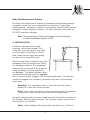
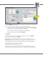
Instruction Manual
Hydroweight Software
Windows Version 5.12
Manual No. X17070
For Cat No. 17061 &17062
Read Warning on Page 3
Specifications subject to change without notice
Ó1998-2011 VacuMed
Vacu·Med
4538 Westinghouse Street
Ventura CA 93003
Tel: 805-644-7461
FAX: 805-654-8759
E-mail: [email protected]
www.vacumed.com
#17070mnl.vp
Last Update 10/11
1
Contents
1. Must-Read Warning
3
2. Installation
4
3. Calibration
5
4. Software Installation
5
5. Running the Software
6
6. Preparing the Subject
7
7. Tare Weight Procedure
7
8. Underwater Weighing
8
9. Printing
9
GENERAL INFORMATION
The water in the tank must be treated with chlorine and checked for proper
ph level. We suggest you purchase appropriate chemicals and a test kit from
your local swimming pool supply house. You may also wish to buy a pool
ladder for easy access to the tank.
You will also need a weighing scale, a thermometer to measure water
temperature and a method to measure Residual Volume (RV) or a spirometer
to measure Vital Capacity for the estimation of RV.
See also model 17400 Residual Volume Measurement System available from
VacuMed.
Warning
THE SOFTWARE AND USER MANUAL ARE BOTH PROTECTED
BY U.S. COPYRIGHT LAW (TITLE 17 UNITED STATES CODE).
UNAUTHORIZED REPRODUCTION AND/OR SALES MAY RESULT IN
IMPRISONMENT OF UP TO 1 YEAR AND FINES OF UP TO $10,000
(17USC 506). COPYRIGHT INFRINGERS MAY ALSO BE
SUBJECT TO CIVIL LIABILITY.
2
Warning
Read this. Your life may depend on it.
Improper installation could cause death by electrocution.
• Lethal voltages may cause death if this system is
not installed properly.
• This installation must be done by an expert in
installing electrical systems near swimming pools
and other water vessels.
• VacuMed cannot give you advice about safe
installation. Building codes vary, but they all require
the installation of special GFI circuits.
• If the electrical contractor that is handling the
installation is unsure, beware! Get a second opinion
or inspection by a qualified electrical engineer or
local government building code inspector.
• Look in the Yellow Pages under Swimming Pools
or Spas. Call a swimming pool supplier and ask
them to recommend an electrical contractor
familiar with Spa installations.
• Installation of our equipment may require a permit
from your local government building and or safety
agency. Check with them. Failure to get such
permit may subject you to fines.
• Warning: Test subjects with long hair must wear a
hair net. Know how to shut off the pump quickly in
case you choose to ignore this hair net warning.
• Take care to hang the transducer from the support
arm using the hardware supplied. The transducer
wire should be secured to the supports using the
plastic wire ties supplied in the package. The digital
indicator must be placed in a location where it
cannot fall, or be accidentally dragged, into the
hydrostatic tank. The indicator should be plugged
into a properly grounded outlet with a ground fault
interrupter (GFI).
3
Body Fat Measurement System
The Body Fat Measurement System is a hardware and software package
designed to allow the user to automate the collection of hydrostatic
measurements. Hardware included in this package should include a single
transducer, digital weighing indicator, a 2 button remote control and an
RS-232C computer interface.
Note: This manual may not reflect all changes caused by changing
to a different hardware supplier in 2007.
2. INSTALLATION
Install the stainless steel upright
supports, mount the crossbar. In a
room with a low ceiling you may need
to tilt the tank horizontally to do this.
Now install the two hoses connecting
the tank to the pump/filter unit.
Once this has been completed, hang the
transducer from the support arm using
the hardware supplied. The transducer
cable should be secured to the supports
using the plastic wire ties supplied in
the package. The digital indicator must
be placed in a location where it can not
fall, or be accidentally dragged, into the hydrostatic tank. The indicator
should be plugged into a properly grounded outlet with a ground fault
interrupter.
Warning: It is mandatory that you have an electrical expert
assist you in this step of the process.
Note: We cannot, and will not, give you advice about the electrical
connection, read the warning on the previous page again!
Hang the weighing chair from the transducer and connect the computer to
the indicator with the cable provided. The 2-button remote control box is
hard-wired to the indicator.
Note: Initial heating of the tank water may take up to 10 hours.
4
3. CALIBRATION
Note: The transducer and indicator have been calibrated prior
to shipment. Do not make any adjustments.
The indicator will show an initial negative weight.
This is normal, because you must always use the supplied weight
belt. The system will not TARE while there is a negative reading.
It is easy to check the calibration by hanging objects of known weight on the
transducer. For example, hang the supplied weight belt or any 2-3kg weight
from the transducer and press the TARE button (left). The indicator should
now indicate zero weight. Now add an object of known weight on the
transducer and read the weight. If the calibration is not within acceptable
limits the system must be re-calibrated. Directions for this procedure are
contained in the Instruction Manual of the indicator. It is important to note
that calibration must be done with a weight close to the maximum capacity of
the transducer (250 pounds).
4. SOFTWARE INSTALLATION
The software supplied with this package is contained on a CD labeled TurboFit
"Hydro-Weight".
Install the software to your hard disk, to do so insert software into your CD
drive and type:
D: setup.exe
(Enter)
(or find setup.exe on the CD)
Continue as prompted
The next step in installing the system is to determine if your computer
system has an available serial port. If your computer does not presently
have an available serial port, you must install one, or install a Serial to USB
adapter, your local computer store can help you. If your computer has a
serial port and it is not being used by another device, then it may be used for
this system. The standard software supplied with this package is designed to
read from the connected/active communication port.
In TurboFit, click on Setup, then User Header to enter the name of your
laboratory to be printed on report.
Note: USB Connections
If you have both an RV system and a Loadcell, both USB cables must be
connected to open the software
5
5. RUNNING THE SOFTWARE
5.1. Click on the TurboFit icon
5.2. Click on Calibration to enter ambient temperature, pressure and humidity.
5.3. Go direct to Quit to Test or click Hydro-Weight on Main Menu.
5.4. Click on New to enter information for a new subject and Save,
or Previous to recall a previously tested subject.
5.5. If using Load Cell Indicator 17070 or 17071,
make sure Comm Port box is checked, unless you want to enter
weight manually. A list of available COM ports is shown in the Comm Port
window. The default is COM 1, but you may need to change it.
If no results are recorded in step 8.2, come back here and select a
different available COM port.
5.6. Enter known Residual Volume or click on Estimated Residual Volume*
and enter Vital Capacity so that software will calculate residual volume
or, if importinga RV value from an RV test, open the *.RV file first,
then click on IMPORT RV.
5.7. Enter Water Temperature
Click
this SAVE button
to save Name, etc
5.8. Click Continue
*Note: Estimated Residual Volume is computed using the following formula:
Males:
RV = Vital Capacity · 0.24 (VC x 0.24)
Females: RV = Vital Capacity · 0.28 (VC x 0.28)
6
6. PREPARE THE SUBJECT
Note: Some users have the test subjects shower before entering
the tank to keep tank water clean.
Test subjects should try to rub out air bubbles trapped
in body hair before taking a weight to minimize errors.
Warning: Every test subject with long hair must wear a hair net to
prevent their hair from being sucked into the pump.
Do not use a rubber cap that might trap air under the cap.
You are now ready to conduct a hydrostatic weighing session. Have the
subject enter the tank and stand to the side or front of the weighing chair.
Have the subject place the weight belt on the chair. Practice with the subject
expelling all the air from their lungs. To expel air, it is suggested that the
subject be directed to begin to slowly exhale air prior to submerging and as
they get to the end of their expiration they submerge and continue to
complete exhalation. Direct the subject to move slowly in the tank to reduce
the dynamic effects of moving water. If you notice a great deal of variability
in your measurements, try using more weight on the subject. (If weight is
added you must proceed through all the steps, e.g. a new TARE, prior to data
collection). This is a learned skill so it may take some practice. A large error
may be introduced into your measurement unless the water in the tank
remains calm when you are taking a tare or net weight.
7. TARE WEIGHT PROCEDURE
Hold the Remote Control box with the buttons facing up and the cable
connector pointed toward you, then the button on the left is the TARE button,
the button on the right is the PRINT button. These buttons functions the
same as the buttons on the indicator.
The indicator may be turned on by connecting it to a power source. This
starting procedure should be done before each testing session and before
each subject. You will note there is no off position, when not in use the
system should be unplugged. You are now ready to proceed.
Place the weight belt in the chair. When the subject is ready, have him/her
slowly expel their air and submerge their head while not sitting in the chair.
The total body should be submerged and no part of the subject should be
leaning on the weighing chair. Add additional weights to the weight belt if
the weighing indicator shows a negative weight.
7
When all the subject’s air is expelled and the is water quiet, press the TARE
button on the indicator or on the hand held remote control. This procedure
zeros the weight of the chair and weight belt. The weight should now
indicate “0.0" and the NET indicator will light up. The weight placed on the
chair must be sufficient to record a positive weight on the indicator prior to
pressing TARE.
If you encounter a problem and desire to take a second tare weight, just
press the TARE button again. This will replace the old tare weight.
8. UNDERWATER WEIGHING
The subject can now place the weight belt around their waist and get into the
chair. No part of their body should be touching the sides or bottom of the
tank.
You are now ready to collect data. Have the subject slowly empty his/her
lungs and lean forward and submerge. Do this slowly so the water is not
disturbed. When the bubbles stop press the PRINT button on the indicator or
the right button on the hand held remote control. The computer will beep
when the data is received and will display the data. This beep is the signal
for the test subject to surface.
Software Procedure
8.1. Follow Subject Testing Prompts. You can repeat weighing without
re-TARE by following the on-screen "Subject Testing" prompts again.
8.2. Each time PRINT is pressed a new trial (H2O Weight in kg) is recorded
in the table.
8.3. Check "Select to Average" boxes to average trials you select.
(Leave out results that are not close to average "outliers")
The RESULTS button will turn green after the first "Select to average".
8.4. Click RESULTS to see %Body Fat for trial(s) checked.
(SAVE button now turns green)
8.5. You MUST click SAVE to save trials, or data file can not be retrieved.
8.6. Click REPORT for Print Preview
8.7. If desired, click into bottom of page to add comments
8
Click
this SAVE button
to save data
8.8. Click PRINT to print report
8.9. For manual entry of underwater weight uncheck the box
"Use Comm Port" in the Patient Info Screen click into the H2O Weight
field, enter the underwater weight and hit ENTER.
You can view the result immediately by clicking Results,
then get a printed record by clicking Report.
9. Printing
To print a report from a previously tested subject, click on the Review
button, select the file and click Open.
Note that you can add comments prior to printing by clicking into the
Comments section at the bottom of the page. The numbers at the bottom
of the page represent the in-water weight in kg for each trial averaged.
Hydro weight files are saved as *.hdwt files.
Residual Volume files are saved as *.RV.
This program is a part of VacuMed's TurboFit VO2 measurement system.
You may view those features by selecting a *.stress file in the Review menu.
9
INFORMATION AND PROBLEMS
The largest source of error in hydrostatic weighing is the inability of the test
subjects to clear their lungs, transducer bounce, and estimation of residual
volume. It takes practice to get accurate results.
Desirable body weight (in pounds) is calculated as follows:
Females: 45.5 + (0.91 x (height in cm - 152.4)) x 2.2046
Males: 50 + (0.91 x (height in cm - 152.4)) x 2.2046
Body Composition Calculation Source
SIRI, W. E. Body Composition from Fluid Spaces and Density. Donner Lab.
Med. Physics (Univ. Calif.) Rept. of 19 March, 1956
USB Connections
If you have both an RV system and a Loadcell, both USB cables must be
connected to open the software
Cable Problems
A standard RS232 cable is hardwired to the rear panel on indicators delivered
after 2006.
Units delivered before 2006 require a modified "Null-modem" cable,
contact VacuMed.
Warning: Lengthening the cable between loadcell and indicator
may un-balance loadcell, factory re-balance will be required.
Revision History
28 Nov 2005:
16 Dec 2006
14 Sep 2008
20 Oct 2008
7 Aug 2009
8 Oct 2011
Initial Issue
Minor corrections, add H2O weight at bottom of report
Corrections for new indicator
Explain SAVE buttons
Minor clarifications
Simplify software procedure and change manual accordingly
10
11
2