1
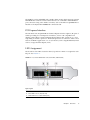
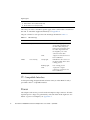
Sun Dual Port 4x QDR IB Host
Channel Adapter PCIe
User’s Guide
Part No. 820-6536-13
April 2010, Revision A
Copyright © 2009, 2010, Oracle and/or its affiliates. All rights reserved.
This software and related documentation are provided under a license agreement containing restrictions on use and disclosure and are
protected by intellectual property laws. Except as expressly permitted in your license agreement or allowed by law, you may not use, copy,
reproduce, translate, broadcast, modify, license, transmit, distribute, exhibit, perform, publish, or display any part, in any form, or by any
means. Reverse engineering, disassembly, or decompilation of this software, unless required by law for interoperability, is prohibited.
The information contained herein is subject to change without notice and is not warranted to be error-free. If you find any errors, please report
them to us in writing.
If this is software or related software documentation that is delivered to the U.S. Government or anyone licensing it on behalf of the U.S.
Government, the following notice is applicable:
U.S. GOVERNMENT RIGHTS Programs, software, databases, and related documentation and technical data delivered to U.S. Government
customers are "commercial computer software" or "commercial technical data" pursuant to the applicable Federal Acquisition Regulation and
agency-specific supplemental regulations. As such, the use, duplication, disclosure, modification, and adaptation shall be subject to the
restrictions and license terms set forth in the applicable Government contract, and, to the extent applicable by the terms of the Government
contract, the additional rights set forth in FAR 52.227-19, Commercial Computer Software License (December 2007). Oracle USA, Inc., 500
Oracle Parkway, Redwood City, CA 94065.
This software or hardware is developed for general use in a variety of information management applications. It is not developed or intended for
use in any inherently dangerous applications, including applications which may create a risk of personal injury. If you use this software or
hardware in dangerous applications, then you shall be responsible to take all appropriate fail-safe, backup, redundancy, and other measures to
ensure the safe use. Oracle Corporation and its affiliates disclaim any liability for any damages caused by use of this software or hardware in
dangerous applications.
Oracle is a registered trademark of Oracle Corporation and/or its affiliates. Oracle and Java are registered trademarks of Oracle and/or its
affiliates. Other names may be trademarks of their respective owners.
AMD, Opteron, the AMD logo, and the AMD Opteron logo are trademarks or registered trademarks of Advanced Micro Devices. Intel and Intel
Xeon are trademarks or registered trademarks of Intel Corporation. All SPARC trademarks are used under license and are trademarks or
registered trademarks of SPARC International, Inc. UNIX is a registered trademark licensed through X/Open Company, Ltd.
This software or hardware and documentation may provide access to or information on content, products, and services from third parties.
Oracle Corporation and its affiliates are not responsible for and expressly disclaim all warranties of any kind with respect to third-party content,
products, and services. Oracle Corporation and its affiliates will not be responsible for any loss, costs, or damages incurred due to your access to
or use of third-party content, products, or services.
Please
Recycle
Contents
Safety Agency Compliance Statements
Regulatory Compliance Statements
Declaration of Conformity
Preface
1.
ix
xi
xiii
Overview
1
Adapter Hardware Overview
IB-HCA Card
2
I/O Interfaces
2
1
InfiniBand Interface
2
PCI Express Interface
LED Assignment
3
3
I2C Compatible Interface
Power
4
4
Node GUID
5
Hardware and Software Requirements
2.
v
IB-HCA Card Installation
Installing the IB-HCA Card
5
7
7
iii
▼
3.
Install the Adapter
7
InfiniBand Software on the Solaris Operating System and Linux
InfiniBand Software on the Solaris Operating System
InfiniBand Software for Solaris 10
10
10
Sun Firmware Flash Update Tool for IB-HCAs
▼
10
Verify the Installation With the Solaris 10 OS
11
Sun Firmware Version for IB-HCAs on the Solaris OS
Using InfiniBand Devices on the Solaris 10 OS
Troubleshooting
▼
Download the MLNX_OFED Software and Documentation
▼
Install the MLNX_OFED Software on a Sun Server
Boot Over InfiniBand on Linux
▼
14
15
Download the Boot Over IB Software and Documentation
16
Additional InfiniBand Software for Linux
17
Product Specifications
19
Adapter Specifications
19
Replacing a Short Bracket With a Tall Bracket on an IB-HCA Card
21
▼
Remove the Short Bracket From the Adapter
▼
Assemble and Install a Tall Bracket
Index
15
16
Verify the Installation With Linux
Short Bracket Replacement
iv
14
15
Verifying the Installation With Linux
B.
13
13
Internet Protocol Over InfiniBand on Linux
A.
12
13
InfiniBand Support Software for Linux
▼
9
24
27
Sun Dual Port 4x QDR IB Host Channel Adapter PCIe User’s Guide • April 2010
22
21
Safety Agency Compliance
Statements
Read this section before beginning any procedure. The
following text provides safety precautions to follow when
installing a Sun Microsystems product.
Depending on the type of power switch your device has,
one of the following symbols may be used:
On – Applies AC power to the system.
Off – Removes AC power from the system.
Safety Precautions
For your protection, observe the following safety
precautions when setting up your equipment:
■
Follow all cautions and instructions marked on the
equipment.
■
Ensure that the voltage and frequency of your power
source match the voltage and frequency inscribed on
the equipment’s electrical rating label.
■
Never push objects of any kind through openings in
the equipment. Dangerous voltages may be present.
Conductive foreign objects could produce a short
circuit that could cause fire, electric shock, or damage
to your equipment.
Symbols
The following symbols may appear in this book:
Caution – There is a risk of personal injury
and equipment damage. Follow the
instructions.
Standby – The On/Standby switch is in the
standby position.
Modifications to Equipment
Do not make mechanical or electrical modifications to the
equipment. Sun Microsystems is not responsible for
regulatory compliance of a modified Sun product.
Placement of a Sun Product
Caution – Do not block or cover the openings
of your Sun product. Never place a Sun
product near a radiator or heat register.
Failure to follow these guidelines can cause
overheating and affect the reliability of your
Sun product.
System Unit Cover
Caution – Hot surface. Avoid contact.
Surfaces are hot and may cause personal
injury if touched.
Caution – Hazardous voltages are present. To
reduce the risk of electric shock and danger to
personal health, follow the instructions.
You must remove the cover of your Sun computer system
unit to add cards, memory, or internal storage devices. Be
sure to replace the cover before powering on your computer
system.
Caution – Do not operate Sun products
without the cover in place. Failure to take this
precaution may result in personal injury and
system damage.
v
Conformité aux normes de sécurité
Veuillez lire attentivement cette section avant de
commencer. Ce texte traite des mesures de sécurité qu’il
convient de prendre pour l’installation d’un produit Sun
Microsystems.
Mesures de sécurité
Pour votre sécurité, nous vous recommandons de suivre
scrupuleusement les mesures de sécurité ci-dessous lorsque
vous installez votre matériel:
■
Suivez tous les avertissements et toutes les
instructions inscrites sur le matériel.
■
Assurez-vous que la tension et la fréquence de votre
source d'alimentation correspondent à la tension et à
la fréquence indiquées sur l'étiquette de la tension
électrique nominale du matériel
■
N'introduisez jamais d'objets quels qu'ils soient dans
les ouvertures de l'équipement. Vous pourriez vous
trouver en présence de hautes tensions dangereuses.
Tout objet étranger conducteur risque de produire un
court-circuit pouvant présenter un risque d'incendie
ou de décharge électrique, ou susceptible
d'endommager le matériel.
Symboles
Vous trouverez ci-dessous la signification des différents
symboles utilisés:
Attention – Vous risquez d'endommager le
matériel ou de vous blesser. Veuillez suivre les
instructions.
Attention – Surfaces brûlantes. Evitez tout
contact. Les surfaces sont brûlantes. Vous
risquez de vous blesser si vous les touchez.
Attention – Tensions dangereuses. Pour
réduire les risques de décharge électrique et
de danger physique, observez les consignes
indiquées.
Marche – Met le système sous tension
alternative.
Arret – Met le système hors tension
alternative.
Veilleuse – L'interrupteur Marche/Veille est
sur la position de veille.
Modification du matériel
N'apportez aucune modification mécanique ou électrique
au matériel. Sun Microsystems décline toute responsabilité
quant à la non-conformité éventuelle d'un produit Sun
modifié.
Positionnement d’un produit Sun
Attention – Evitez d'obstruer ou de recouvrir
les orifices de votre produit Sun. N'installez
jamais un produit Sun près d'un radiateur ou
d'une source de chaleur. Si vous ne respectez
pas ces consignes, votre produit Sun risque de
surchauffer et son fonctionnement en sera
altéré.
Couvercle de l'unité
Pour ajouter des cartes, de la mémoire ou des périphériques
de stockage internes, vous devez retirer le couvercle de
votre système Sun. Remettez le couvercle supérieur en
place avant de mettre votre système sous tension.
Attention – Ne mettez jamais des produits
Sun sous tension si leur couvercle supérieur
n'est pas mis en place. Si vous ne prenez pas
ces précautions, vous risquez de vous blesser
ou d'endommager le système.
Selon le type d'interrupteur marche/arrêt dont votre
appareil est équipé, l'un des symboles suivants sera utilisé:
vi
Sun Dual Port 4x QDR IB Host Channel Adapter PCIe User’s Guide • April 2010
Einhaltung sicherheitsbehördlicher
Vorschriften
Lesen Sie vor dem Ausführen von Arbeiten diesen
Abschnitt. Im folgenden Text werden Sicherheitsvorkehrungen beschrieben, die Sie bei der Installation eines
Sun Microsystems-Produkts beachten müssen.
Aus– Unterbricht die Wechselstromzufuhr
zum Gerät.
Wartezustand – Der Ein-/Standby-Netzschalter befindet sich in der Standby-Position.
Sicherheitsvorkehrungen
Treffen Sie zu Ihrem eigenen Schutz bei der Installation des
Geräts die folgenden Sicherheitsvorkehrungen:
■
Beachten Sie alle auf den Geräten angebrachten
Warnhinweise und Anweisungen.
■
Stellen Sie sicher, dass Spannung und Frequenz der
Stromversorgung den Nennleistungen auf dem am
Gerät angebrachten Etikett entsprechen.
■
Führen Sie niemals Fremdobjekte in die Öffnungen
am Gerät ein. Es können gefährliche Spannungen
anliegen. Leitfähige Fremdobjekte können einen
Kurzschluss verursachen, der einen Brand, Stromschlag oder Geräteschaden herbeiführen kann.
Symbole
Die Symbole in diesem Handbuch haben folgende
Bedeutung:
Modifikationen des Geräts
Nehmen Sie keine elektrischen oder mechanischen
Gerätemodifikationen vor. Sun Microsystems ist für die
Einhaltung der Sicherheitsvorschriften von modifizierten
Sun-Produkten nicht haftbar.
Gehäuseabdeckung
Sie müssen die Abdeckung Ihres Sun-Computersystems
entfernen, um Karten, Speicher oder interne Speichergeräte
hinzuzufügen. Bringen Sie vor dem Einschalten des
Systems die Gehäuseabdeckung wieder an.
Achtung – Nehmen Sie Sun-Geräte nicht ohne
Abdeckung in Betrieb. Die Nichtbeachtung
dieses Warnhinweises kann Verletzungen oder
Geräteschaden zur Folge haben.
Achtung – Gefahr von Verletzung und
Geräteschaden. Befolgen Sie die Anweisungen.
Achtung – Heiße Oberfläche. Nicht berühren,
da Verletzungsgefahr durch heiße Oberfläche
besteht.
Achtung – Gefährliche Spannungen. Befolgen
Sie die Anweisungen, um Stromschläge und
Verletzungen zu vermeiden.
Je nach Netzschaltertyp an Ihrem Gerät kann eines der
folgenden Symbole verwendet werden:
Ein – Versorgt das System mit Wechselstrom.
Safety Agency Compliance Statements
vii
Normativas de seguridad
Lea esta sección antes de realizar cualquier operación. En
ella se explican las medidas de seguridad que debe tomar al
instalar un producto de Sun Microsystems.
Medidas de seguridad
Apagado – Corta la alimentación de CA del
sistema.
Espera – El interruptor de encendido/espera
está en la posición de espera.
Para su protección, tome las medidas de seguridad
siguientes durante la instalación del equipo:
■
Siga todos los avisos e instrucciones indicados en el
equipo.
■
Asegúrese de que el voltaje y frecuencia de la fuente
de alimentación coincidan con el voltaje y frecuencia
indicados en la etiqueta de clasificación eléctrica del
equipo.
■
No introduzca objetos de ningún tipo por las rejillas
del equipo, ya que puede quedar expuesto a voltajes
peligrosos. Los objetos conductores extraños pueden
producir cortocircuitos y, en consecuencia, incendios,
descargas eléctricas o daños en el equipo.
Símbolos
En este documento aparecen los siguientes símbolos:
Modificaciones en el equipo
No realice modificaciones de tipo mecánico ni eléctrico en el
equipo. Sun Microsystems no se hace responsable del
cumplimiento de normativas en caso de que un producto
Sun se haya modificado.
Colocación de un producto Sun
Precaución – No obstruya ni tape las rejillas
del producto Sun. Nunca coloque un producto
Sun cerca de radiadores ni fuentes de calor. Si
no sigue estas indicaciones, el producto Sun
podría sobrecalentarse y la fiabilidad de su
funcionamiento se vería afectada.
Precaución – Existe el riesgo de que se
produzcan lesiones personales y daños en el
equipo. Siga las instrucciones.
Precaución – Superficie caliente. Evite todo
contacto. Las superficies están calientes y
pueden causar lesiones personales si se tocan.
Precaución – Voltaje peligroso. Para reducir
el riesgo de descargas eléctricas y lesiones
personales, siga las instrucciones.
En función del tipo de interruptor de alimentación del que
disponga el dispositivo, se utilizará uno de los símbolos
siguientes:
Encendido – Suministra alimentación de CA
al sistema.
viii
Sun Dual Port 4x QDR IB Host Channel Adapter PCIe User’s Guide • April 2010
Regulatory Compliance Statements
Your Sun product is marked to indicate its compliance class:
• Federal Communications Commission (FCC) — USA
• Industry Canada Equipment Standard for Digital Equipment (ICES-003) — Canada
• Voluntary Control Council for Interference (VCCI) — Japan
• Bureau of Standards Metrology and Inspection (BSMI) — Taiwan
Please read the appropriate section that corresponds to the marking on your Sun product before attempting to install the
product.
FCC Class A Notice
This device complies with Part 15 of the FCC Rules. Operation is subject to the following two conditions:
1. This device may not cause harmful interference.
2. This device must accept any interference received, including interference that may cause undesired operation.
Note: This equipment has been tested and found to comply with the limits for a Class A digital device, pursuant to Part 15 of
the FCC Rules. These limits are designed to provide reasonable protection against harmful interference when the equipment
is operated in a commercial environment. This equipment generates, uses, and can radiate radio frequency energy, and if it is
not installed and used in accordance with the instruction manual, it may cause harmful interference to radio communications.
Operation of this equipment in a residential area is likely to cause harmful interference, in which case the user will be required
to correct the interference at his own expense.
Modifications: Any modifications made to this device that are not approved by Sun Microsystems, Inc. may void the authority
granted to the user by the FCC to operate this equipment.
ICES-003 Class A Notice - Avis NMB-003, Classe A
This Class A digital apparatus complies with Canadian ICES-003.
Cet appareil numérique de la classe A est conforme à la norme NMB-003 du Canada.
ix
BSMI Class A Notice
The following statement is applicable to products shipped to Taiwan and marked as Class A on the product compliance
label.
CCC Class A Notice
The following statement is applicable to products shipped to China and marked with “Class A” on the product’s compliance
label.
x
Sun Dual Port 4x QDR IB Host Channel Adapter PCIe User’s Guide • April 2010
Declaration of Conformity
To receive a copy of the latest Declaration of Conformity (DoC) for the product, either contact your
local Sun sales representative, or create an online request at:
(https://www2.sun.de/dct/forms/reg_us_1607_755_0.jsp)
xi
xii
Sun Dual Port 4x QDR IB Host Channel Adapter PCIe User’s Guide • April 2010
Preface
This guide provides an overview, installation instructions, and specifications of the
Sun Dual Port 4x DDR IB Host Channel Adapter PCIe low-profile card. The
instructions in this guide are designed for system administrators with experience
installing network hardware and software.
Note – The Sun Dual Port 4x DDR IB Host Channel Adapter PCIe is based on
Mellanox Technologies’ MT26428 ConnectX IB adapter (HCA) device.
Related Documentation
The following table lists the documentation for this product. The online
documentation is available at:
http://docs.sun.com/app/docs/prod/qdr.pcie
Application
Title
Part Number
Format
Location
Unpacking
the product
Sun Dual Port 4x QDR IB Host Channel Adapter PCIe Getting 820-6538
Started Guide
Printed Shipping kit
PDF
Online
Installation
and use
Sun Dual Port 4x QDR IB Host Channel Adapter PCIe User’s
Guide (this document)
820-6536
PDF
HTML
Online
Latest
Information
Sun Dual Port 4x QDR IB Host Channel Adapter PCIe Product 820-6537
Notes
PDF
HTML
Online
Solaris
support
Solaris 10 Operating System documentation collection
http://docs.sun.com/app/docs/prod/solaris.10
PDF
HTML
Online
xiii
If you download software from Mellanox Technologies, as described in this manual,
you might also need documentation that is available at:
http://www.mellanox.com
Details on locating specific manuals at this web site are provided in Chapter 3.
Application
Title
Format
Location
Installing Linux support
software
Mellanox OFED for Linux Installation Guide
PDF
Online
Use of Linux support
software and IPoIB
features
Mellanox OFED Stack for Linux User’s Manual
PDF
Online
Latest information on
Linux support software
Mellanox OFED for Linux Release Notes
Text file
Online
Use of BoIB features
Boot over IB (BoIB) User’s Manual
PDF
Online
Latest information on
BoIB
Mellanox Boot over IB (BoIB) in “Mellanox OFED
for Linux” Release Notes
Text file
Online
Documentation, Support, and Training
Sun Function
URL
Documentation
http://docs.sun.com
Support
http://www.sun.com/support/
Training
http://www.sun.com/training/
Third-Party Web Sites
Sun is not responsible for the availability of third-party web sites mentioned in this
document. Sun does not endorse and is not responsible or liable for any content,
advertising, products, or other materials that are available on or through such sites or
xiv
Sun Dual Port 4x QDR IB Host Channel Adapter PCIe User’s Guide • April 2010
resources. Sun will not be responsible or liable for any actual or alleged damage or
loss caused by or in connection with the use of or reliance on any such content,
goods, or services that are available on or through such sites or resources.
Information
URL
PCI Express specifications
http://www.pcisig.com
Mellanox Technologies HCA information,
firmware downloads, and Linux software
downloads
http://www.mellanox.com
OFED information
http://www.openfabrics.org
InfiniBand Specifications
http://infinibandta.org/
Documentation Feedback
Sun is interested in improving its documentation and welcomes your comments and
suggestions. You can submit your comments by going to:
http://www.sun.com/hwdocs/feedback
Please include the title and part number of your document with your feedback:
Sun Dual Port 4x QDR IB Host Channel Adapter PCIe User’s Guide, part number 8206536-13.
Preface
xv
xvi
Sun Dual Port 4x QDR IB Host Channel Adapter PCIe User’s Guide • April 2010
CHAPTER
1
Overview
This chapter includes:
■
“Adapter Hardware Overview” on page 1
■
“Hardware and Software Requirements” on page 5
Adapter Hardware Overview
The main features of the Sun Dual Port 4x QDR IB Host Channel Adapter PCIe lowprofile card are as follows:
■
IBTA (InfiniBand Trade Association) v1.2 compliant
■
Two 4x InfiniBand copper ports for connecting InfiniBand traffic (4x IB
connectors)
■
PCIe 2.0 card
■
PCI Express expansion board with an x8 edge connector compatible to the PCI
Express 1.0a specification
■
Media detect circuit, which supports external InfiniBand fiber solutions
■
European Union Restriction of Hazardous Substances (RoHS) compliant
■
4x IB port speed support: 10 Gbps, 20 Gbps, or 40 Gbps (QDR - Quad data rate)
■
Short mounting bracket (an alternative tall bracket is supplied along with the
card)
1
IB-HCA Card
FIGURE 1-1
Sun Dual Port 4x QDR IB Host Channel Adapter PCIe With Short Bracket
I/O Interfaces
Each IB-HCA card includes the following interfaces:
■
Two 4x InfiniBand QSFP connectors
■
PCI Express x8 edge connector
■
I/O panel LEDs
InfiniBand Interface
The Sun Dual Port 4x QDR IB Host Channel Adapter PCIe is compliant with the
InfiniBand Architecture Specification, Release 1.2. The device has two compliant 4x
InfiniBand ports, called 1 and 2. The IB-HCA card provides access to these ports by
means of two 4x InfiniBand connectors for external InfiniBand copper cables. These
cables must be compliant with the InfiniBand Architecture Specification, Release 1.2.
Connector 1 connects to Port 1 of the device, while connector 2 connects to Port 2.
2
Sun Dual Port 4x QDR IB Host Channel Adapter PCIe User’s Guide • April 2010
The IB-HCA card is embedded with a media detect circuit, which supports external
InfiniBand fiber solutions. These external devices are connected to the InfiniBand
port connectors using active media converters, such as the Emcore QTR3400 Smart
Module or the Fujitsu FPD-010R008-0E o-microGiGaCN.
PCI Express Interface
The Sun Dual Port 4x QDR IB Host Channel Adapter PCIe has eight Tx/Rx pairs of
SerDes providing for a PCI Express x8 interface, version 1.0a compatible. The
adapter can be either a master initiating the PCI Express bus operations or a slave
responding to PCI bus operations. The PCI Express bus can connect to either a host
CPU in an IB-HCA application or to an I/O device (such as Gigabit Ethernet) when
used as a target channel adapter (TCA).
LED Assignment
The board has four LEDs located on the I/O panel. Two LEDs are assigned to each
4X port. See FIGURE 1-2.
FIGURE 1-2
I/O Panel With Dual Ports and LEDs (Tall Bracket)
Figure Legend
1
InfiniBand Port 1
2
Green LED for Port 1 (Physical Link)
3
Amber LED for Port 1 (Data Activity Link)
Chapter 1
Overview
3
Figure Legend
4
InfiniBand Port 2
5
Amber LED for Port 2 (Data Activity Link)
6
Green LED for Port 2 (Physical Link)
The same port names and LED footprints apply when a tall bracket is installed on
the card. To install the supplied tall bracket, see Appendix B.
The pair of LEDs for each port have the meanings described in TABLE 1-1.
TABLE 1-1
LED Meanings
LED Color
LED Name
LED State
Meaning
Green
Physical Link
Lit
The link bringup process has
successfully completed and
the link width, link speed,
link polarity, and link reversal
have been negotiated with
the neighbor port on the
other end of the cable.
Unlit
A physical connection has not
been established.
Steady light
Infiniband is discovered over
the physical link, but no data
is being passed.
Blinking light
Data is being passed.
Unlit
A physical or logical
connection (or both) has not
been established.
Amber
Data Activity
I2C Compatible Interface
A three-pin header, designated with reference name J5 on the IB-HCA card, is
provided as the I2C compatible interface.
Power
The adapter card receives power from the PCI Express edge connector. All other
required power voltages are generated by on-board switch mode regulators. For
details on power consumption, see Appendix A.
4
Sun Dual Port 4x QDR IB Host Channel Adapter PCIe User’s Guide • April 2010
Node GUID
A label on the back of the Sun Dual Port 4x QDR IB Host Channel Adapter PCIe
card displays the 64-bit GUID. This GUID uniquely identifies this device in the
server and on the IB fabric.
Hardware and Software Requirements
For the latest list of supported platforms and operating systems, refer to the Sun
Dual Port 4x QDR IB Host Channel Adapter PCIe Product Notes, part number 820-6537.
This document is available at http://docs.sun.com.
Chapter 1
Overview
5
6
Sun Dual Port 4x QDR IB Host Channel Adapter PCIe User’s Guide • April 2010
CHAPTER
2
IB-HCA Card Installation
The IB-HCA card is a standard PCI Express (PCIe) x8 card with a standard x8 edge
connector. Consult the server documentation for instructions on how to install a PCI
Express card into that system.
This chapter includes:
■
“Installing the IB-HCA Card” on page 7
■
“Install the Adapter” on page 7
Installing the IB-HCA Card
Caution – Electronic components on printed circuit boards are extremely sensitive
to static electricity. Ordinary amounts of static electricity generated by your clothing
or work environment can damage the electronic equipment. When installing the IBHCA card in a system, use antistatic grounding straps and antistatic mats to help
prevent damage due to electrostatic discharge.
▼ Install the Adapter
Refer to your system installation or service manual for detailed instructions for the
following steps:
1. Check that the bracket on the IB-HCA card is the correct size for your system.
An alternative longer bracket is supplied with the card. If you need to use a
different bracket, perform the instructions in Appendix B.
7
2. Power off your server, using the standard shutdown procedures described in
your system service manual.
Product documentation for Sun servers is available at http://docs.sun.com.
3. Remove the cover from the system to access the card slots and connectors.
4. Select an available PCIe x8 slot and remove the blank front panel for that slot.
Or, if you are replacing an existing card in that slot, remove the card.
5. Install the IB-HCA card into the slot, pushing the card’s edge connector into the
connector on the chassis.
Ensure that the front plate on the IB-HCA card mounts flush with the chassis
panel opening.
6. If applicable, install the screw in the front plate to secure the IB-HCA card into
the chassis.
7. Attach the 4x end of each InfiniBand I/O cable to an IB-HCA port connector.
Ensure that the connectors are properly engaged.
Caution – Avoid putting unnecessary stress on the connection. Do not bend or twist
the cable near the connectors and avoid cable bends of more than 90 degrees.
8. Replace the cover on the unit.
9. If not already connected, connect the other end of the InfiniBand I/O cables to
the appropriate ports on the switch or switches.
The IB-HCA ports can be connected to different ports on the same switch or to a
port on different switches.
10. Turn on power to the system and allow the server to reboot.
This step completes the hardware installation. Proceed to the verification
instructions in “Verify the Installation With the Solaris 10 OS” on page 11 or
“Verifying the Installation With Linux” on page 16.
8
Sun Dual Port 4x QDR IB Host Channel Adapter PCIe User’s Guide • April 2010
CHAPTER
3
InfiniBand Software on the Solaris
Operating System and Linux
InfiniBand is a network architecture for the large-scale interconnection of computing
and I/O nodes through a high-speed switched fabric. To operate InfiniBand on a Sun
server, you need an InfiniBand HCA (the adapter) and an InfiniBand software stack.
This chapter provides an overview of installing and using the InfiniBand software
stack for the Solaris OS and Linux operating system.
Consult the product notes for your server for recent information about supported
operating systems, firmware and software updates, and other issues not covered in
the main product documentation.
This chapter includes:
■
“InfiniBand Software on the Solaris Operating System” on page 10
■
“InfiniBand Support Software for Linux” on page 13
■
“Internet Protocol Over InfiniBand on Linux” on page 15
■
“Boot Over InfiniBand on Linux” on page 15
■
“Verifying the Installation With Linux” on page 16
■
“Additional InfiniBand Software for Linux” on page 17
9
InfiniBand Software on the Solaris
Operating System
InfiniBand software is bundled with the Solaris 10 OS. The package containing the
device driver for the Sun Dual Port 4x QDR IB Host Channel Adapter is
SUNWhermon. The driver name is hermon.
InfiniBand Software for Solaris 10
For details about InfiniBand software supported in Solaris 10 Update releases, refer
to the following documents in the Solaris 10 Release and Installation Collection
available at http://docs.sun.com:
■
Solaris 10 What’s New
■
Solaris 10 Release Notes
■
Solaris 10 Package List
Note – The SUNWhermon package that is available in the Solaris 10 10/09 OS and
subsequent Solaris Update releases must be used with this IB-HCA PCIe.
The InfiniBand software stack, consisting of the upper layer protocols and transport
framework, is included in all of the Solaris software groups described in the Solaris
Installation Guide. The SUNWhermon package is included in the Entire+OEM, Entire,
and Developer software groups. If you are not using any of these groups, you must
explicitly add the SUNWhermon package during initial installation. If you are not
doing a software install, use the pkgadd(1) utility to add the package prior to using
the Sun Dual Port 4x QDR IB Host Channel Adapter PCIe.
Sun Firmware Flash Update Tool for IB-HCAs
The Sun Firmware Flash Update tool in the Solaris 10 OS does not support the Sun
Dual Port 4x QDR IB Host Channel Adapter PCIe. You must download a separate
package containing that tool from the Oracle Download Webpage at:
http://www.sun.com/download/index.jsp.
Go to the Download A-Z tab and search for the "Sun Firmware Flash Utility." Refer
to the installation instructions in the package README file.
10
Sun Dual Port 4x QDR IB Host Channel Adapter PCIe User’s Guide • April 2010
To check that the correct version is installed, type:
# firmwareflash -v
firmwareflash: version v1.9
Note – This command must display version number 1.9 or higher.
▼ Verify the Installation With the Solaris 10 OS
Before you can verify the installation, you must install the adapter in the chassis,
power on the server, and cable the server to an operational InfiniBand switch.
Afterward, perform the following steps:
1. Ensure that the cables are connected to the adapter and switches.
2. Verify that the IB Subnet Manager is running on the IB switch or on a host
within the subnet.
Refer to the manual for the IB Subnet Manager for more information.
3. Check that the green LED is illuminated for each port that is connected to the
switch.
If the green LED is not on, check the cable connections at the adapter and at the
switch.
4. Check that the amber LED is illuminated for each port that is connected to the
switch.
5. Verify that the IB-HCA ports are up and the driver is attached.
a. Use the cfgadm(1m) command to obtain the state of the device installed.
# cfgadm -als "cols=ap_id:condition" hca
Ap_Id
Condition
hca:2C90109763F70
ok
If more than one IB-HCA device is installed in the server, a row is displayed
for each. Look for the row displaying hca:GUID where GUID is the 64-bit
number from the physical label on the IB-HCA card. See “Node GUID” on
page 5.
The Condition column must display ok to indicate that the driver has
discovered the hardware and bound to it. Refer to the cfgadm_ib(1m) man
pages for details about the IB specific extensions.
Chapter 3
InfiniBand Software on the Solaris Operating System and Linux
11
b. Use the cfgadm(1m) command to obtain port GUIDs for each port on the IBHCA card.
# cfgadm -als "cols=ap_id:info" hca
Ap_Id
Information
hca:2C90109763F70
VID: 0x15b3, PID: 0x5a44,
#ports: 0x2, port1 GUID: 0x2C90109763F71, port2 GUID:
0x2C90109763F72
If more than one IB-HCA device is installed in the server, a row is displayed
for each. Look for the row displaying hca:GUID where GUID is the 64-bit
number from the physical label on the IB-HCA card. See “Node GUID” on
page 5.
Use the port number and GUID displayed by this command for your IB-HCA
device in the following step.
c. Use the cfgadm(1m) command to verify that the IB ports and partitions are
configured by the Subnet Manager.
# cfgadm -als "select=type(IB-VPPA),cols=ap_id"
Ap_Id
ib::2C90109763F71,ffff,ipib
ib::2C90109763F72,ffff,ipib
The command displays the AP_ID column where each row has the format of
ib::Port GUID,P_Key,ipib. Match the Port GUIDs from the previous
command with these port GUIDs. There must be one row corresponding to the
port and P_Key setup by the Subnet Manager. If an entry is missing, check the
Subnet Manager configuration.
Sun Firmware Version for IB-HCAs on the Solaris
OS
To use this adapter with the Solaris OS, the minimum firmware version must be
2.7.000. Use the firmwareflash command to display the revision level of your IBHCA card.
# firmwareflash -l -c IB
Look for the revision number that appears after the Firmware revision string. If
more than one HCA device is displayed, look for the Node Image GUID that
matches the GUID displayed on the physical GUID label of the IB-HCA card being
installed. See “Node GUID” on page 5.
12
Sun Dual Port 4x QDR IB Host Channel Adapter PCIe User’s Guide • April 2010
If the firmware version is not at 2.7.000 or higher, update the firmware. Only update
the firmware on your IB-HCA card with files specifically approved for the Oracle
product. Select and download approved firmware files from:
http://www.mellanox.com/support/firmware_table_Sun.php
After obtaining a firmware image, use the firmwareflash command to install the
firmware. Once installed, reboot the system to enable the new firmware.
Using InfiniBand Devices on the Solaris 10 OS
For details about InfiniBand software stack configurations in a Solaris 10 Update
release, refer to the System Administration Guide: Devices and File Systems document in
the Solaris 10 System Administrator Collection available at http://docs.sun.com.
Section 9 of this guide titled Using InfiniBand Devices (Overview/Tasks) describes how
to set up upper layer protocols such as IPoIB and uDAPL.
Troubleshooting
Check the Sun Dual Port 4x QDR IB Host Channel Adapter PCIe Product Notes (8206537) for information about known issues discovered using the Solaris 10 OS with
your IB-HCA card.
When using IPoIB, verify that the broadcast group is configured by the Subnet
Manager in the partition where the IPoIB link will be used.
InfiniBand Support Software for Linux
With most supported Linux releases, you must also install the MLNX_OFED software
stack. This software is the Mellanox OpenFabrics Enterprise Distribution (OFED) for
Linux. Refer to your Linux vendor for software installation recommendations and
support.
Chapter 3
InfiniBand Software on the Solaris Operating System and Linux
13
▼ Download the MLNX_OFED Software and
Documentation
1. Go to the Mellanox Technologies web site:
http://www.mellanox.com
2. Select the Products tab.
3. Select InfiniBand SW/Drivers from the menu for Products.
4. Select Linux SW/Drivers from the menu for InfiniBand SW/Drivers.
5. Select the download that corresponds to your operating system.
Follow those instructions to complete the download.
6. Select and download the related documentation for MLNX_OFED.
At minimum, download copies of these manuals that are offered on the Linux
SW/Drivers page:
■
Installation Guide
■
Linux User’s Manual
■
Release Notes
▼ Install the MLNX_OFED Software on a Sun Server
1. Refer to the Mellanox OFED for Linux Installation Guide you downloaded from the
Mellanox web site.
The instructions in that document are correct for installation on a Sun server
except for a difference explained in the next step.
2. Whenever a procedure in the Mellanox guide calls for running the
mlnxofedinstall script, always include the --without-fw-update option.
This option prevents the MLNX_OFED installation process from automatically
updating the firmware on your Sun HCA. Only update the firmware on that
device using files specifically approved for Sun product. You can select and
download approved firmware files from:
http://www.mellanox.com/support/firmware_table_Sun.php
14
Sun Dual Port 4x QDR IB Host Channel Adapter PCIe User’s Guide • April 2010
Internet Protocol Over InfiniBand on
Linux
Support for Internet Protocol Over InfiniBand (IPoIB) is included in the MLNX_OFED
software distribution. Details on using IPoIB are included in the Mellanox OFED
Stack for Linux User’s Manual.
Boot Over InfiniBand on Linux
Software to enable Boot Over InfiniBand (BoIB) on Linux is available from the
Mellanox Technologies web site.
▼ Download the Boot Over IB Software and
Documentation
1. Go to the Mellanox Technologies web site:
http://www.mellanox.com
2. Select the Products tab.
3. Select Boot Over IB from the menu for Products.
4. Select Linux SW/Drivers from the menu for InfiniBand SW/Drivers.
5. Select Download.
Follow the instructions provided on the web page to complete the download.
6. Select and download the related documentation for BoIB.
At minimum, download copies of these manuals that are offered on the Boot Over
IB page:
■
User’s manual
■
Release notes
Chapter 3
InfiniBand Software on the Solaris Operating System and Linux
15
Verifying the Installation With Linux
Before you can verify the installation, you must install the adapter in the chassis,
power the server, and cable it to an operational InfiniBand switch. The InfiniBand
switch should automatically recognize InfiniBand servers when they are connected
to the fabric.
▼ Verify the Installation With Linux
The InfiniBand switch should automatically recognize the IB-HCA card when it is
connected to the fabric if the IB Subnet Manager is running on the switch, or on a
host within the subnet.
1. Ensure that the cables are connected to the adapter and switches.
2. Verify that the IB Subnet Manager is running on the IB switch or on a host
within the subnet.
Refer to the manual for the IB Subnet Manager for more information.
3. Check that the green LED is illuminated for each port that is connected to the
switch.
If the green LED is not on, check the cable connections at the adapter and at the
switch.
4. Check that the amber LED is illuminated for each port that is connected to the
switch.
5. Verify that the IB-HCA ports are up and the driver is attached:
# ibstat
The output shows system diagnostic messages that have the string mlx4 in the
message (the name of the Linux driver). Included in the output is a message that
indicates whether the port is up or down.
16
Sun Dual Port 4x QDR IB Host Channel Adapter PCIe User’s Guide • April 2010
Additional InfiniBand Software for
Linux
As the popularity of InfiniBand technology increases, the number of Linux
distributions and open source organizations producing drivers and tools will
increase. For up-to-date information, check with open source organizations (such as
http://OpenFabrics.org) and your current vendors.
The OpenFabrics organization is the Open Software solution in the InfiniBand
software space. The OpenFabrics Enterprise Distribution (OFED) is the InfiniBand
suite of software produced by this organization. Various vendors contribute their
drivers (and other software components) to OFED.
Chapter 3
InfiniBand Software on the Solaris Operating System and Linux
17
18
Sun Dual Port 4x QDR IB Host Channel Adapter PCIe User’s Guide • April 2010
APPENDIX
A
Product Specifications
This appendix includes:
■
“Adapter Specifications” on page 19
Adapter Specifications
TABLE A-1 lists the specifications for the IB-HCA card.
TABLE A-1
Specifications for the Dual Port 4x QDR IB Host Channel Adapter PCIe
Physical
Size
Air flow
4x 10Gbps connector
2.54 in. x 5.37 in. (64.4 mm x 136.47 cm)
200 LFM @ 55˚C
InfiniBand (copper, current rating: 0.5A max) with active media
adapter support
Protocol Support
InfiniBand
IBTA v1.2, auto-negotiation
40 Gbps, 5 Gbps
20 Gbps, 5 Gbps
10 Gbps, 2.5 Gbps
QoS
8 InfiniBand virtual lanes for each port
RDMA support
All ports
PCI Express
2.0 SERDES @ 5.0 GT/s
Power and Environmental
Voltage
12 V, 3.3 V
Typical Power
12.23 W
19
TABLE A-1
Specifications for the Dual Port 4x QDR IB Host Channel Adapter PCIe
Maximum Power
14.32 W
Temperature
0˚C to 55˚C
Regulatory
20
Safety
IEC/EN 60950-1:2001, ETSI EN 300 019-2-2
Environmental
IEC 60068-2- 64, 29, 32
RoHS
RoHS-R5
Sun Dual Port 4x QDR IB Host Channel Adapter PCIe User’s Guide • April 2010
APPENDIX
B
Replacing a Short Bracket With a Tall
Bracket on an IB-HCA Card
By default, the Dual Port 4x QDR IB PCIe Host Channel Adapter has a short bracket.
A tall bracket is also provided to accomodate systems that require the longer bracket.
This chapter includes:
■
“Short Bracket Replacement” on page 21
Short Bracket Replacement
Topics include:
■
“Remove the Short Bracket From the Adapter” on page B-22
■
“Assemble and Install a Tall Bracket” on page B-24
FIGURE B-1 shows the bracket-side view of a dual-port IB-HCA card.
21
FIGURE B-1
Short Bracket of the Sun Dual Port 4x QDR IB Host Channel Adapter PCIe
▼ Remove the Short Bracket From the Adapter
1. Remove the bracket screws and washers.
Unscrew both screws from the card using a torque screwdriver (see FIGURE B-2).
22
Sun Dual Port 4x QDR IB Host Channel Adapter PCIe User’s Guide • April 2010
FIGURE B-2
Unscrewing the Short Bracket Screws
Appendix B
Replacing a Short Bracket With a Tall Bracket on an IB-HCA Card
23
2. Detach the bracket.
a. Grip the bracket as shown in FIGURE B-3, placing your thumb on the LED
component.
FIGURE B-3
Detaching the Short Bracket
b. In a rotating move toward the component side of the card, slide the bracket
out of the connectors.
c. Gently hold your thumb on the LED component, as shown in FIGURE B-3. At
the same time extract the bracket, while making sure to protect the LEDs.
d. Make a rotating move to detach the short bracket, as shown in FIGURE B-3.
▼ Assemble and Install a Tall Bracket
1. Place the tall bracket onto the card, as shown in FIGURE B-4.
a. Gently fit the connectors through the bracket connector holes.
b. Ensure that the LEDs are aligned into their intended bracket holes.
24
Sun Dual Port 4x QDR IB Host Channel Adapter PCIe User’s Guide • April 2010
FIGURE B-4
Placing the Tall Bracket Onto the Card and Tightening the Screws
2. Secure the tall bracket to the card with screws.
a. Insert a screw along with a washer into each of the two holes on the card
intended for holding the bracket as shown in FIGURE B-4.
Use a torque screwdriver to apply up to 2 lbs per inch torque on each screw.
Appendix B
Replacing a Short Bracket With a Tall Bracket on an IB-HCA Card
25
26
Sun Dual Port 4x QDR IB Host Channel Adapter PCIe User’s Guide • April 2010
Index
A
mlnxofedinstall script, 14
adapter
power, 4
specifications, 19
O
Open Fabrics Enterprise Distribution (OFED), 13
OpenFabrics organization, 17
B
bracket
height, 1
replacing, 21
F
S
Subnet Manager, 16
V
Verifying the Installation, 16
firmware updates, 14
I
I/O
cables, 8
interfaces, 2
panel, 3
IB Subnet Manager, 16
IB-HCA installation, 8
Internet Protocol Over InfiniBand (IPoIB), 15
L
LED, 16
assignment, 3
location, 3
Linux distributions, 17
Linux support, 9
M
Mellanox Open Fabrics Enterprise Distribution
(MLNX_OFED), 13
27
28
Sun Dual Port 4x QDR IB Host Channel Adapter PCIe User’s Guide • April 2010