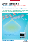
1
3. Communication parameter setting
Communication Installation Instructions
KT4H/B Temperature Controller
No. KT4HCE4 2009.11
These instructions are for communication functions. For detailed operating
instructions, please refer to User’s Manual for the KT4H/B.
Serial communication and Tool port communication cannot be used together.
When performing Serial communication, remove the tool cable (AKT4H820) from
the USB port of the PC and tool connector of the KT4H/B.
When performing Tool port communication, it is not required to remove the Serial
communication cables. However, do not send a command from the master side.
Set each communication parameter following the procedures below.
Proceed to Auxiliary function setting mode.
(1)
Press
key while pressing
key in
the PV/SV display mode. The unit proceeds
to Auxiliary function setting mode.
+
Auxiliary function setting mode
(2)
Press
key twice.
The unit proceeds to Communication protocol
selection.
(Twice)
Communication protocol selection
(3)
Select the communication protocol.
: Modbus ASCII mode (Default)
: Modbus RTU mode
: MEWTOCOL (Slave)
(4)
Instrument number setting
Set the instrument number of the controller
individually when communicating by connecting
plural instruments.
1 to 99 (Default: 1)
(5)
Communication speed selection
Set the communication speed equal to that of
the host computer.
: 2400bps
: 4800bps
: 9600bps (Default)
: 19200bps
(6)
Data bit/Parity selection
Select the data bit and parity.
: 8 bits/No parity
: 7 bits/No parity
: 8 bits/Even
: 7 bits/Even (Default)
: 8 bits/Odd
: 7 bits/Odd
(7)
Stop bit selection
Select the stop bit.
: 1 (Default)
:2
(8)
Communication response time setting
Set the minimum response time.
5 to 99 (Default: 5ms)
[17]
[19]
5. System configuration
Communication converter
RS-232C
RS-485
[20]
KT4H or KT4B
No. 2
No. 1
No. 31
[21]
Host computer
(Fig. 1-1)
2. Wiring
[22]
Wiring example using a communication converter
Using a D-sub 9-pin Connector
KT4H or KT4B
Host computer
Shielded
wire
[23]
FG
FG
[24]
Shielded
wire
FG
Numbers such as [17], [19], etc. are setting item numbers.
Refer to the User’s Manual for the KT4H/B.
D-sub 9-pin connector
4. Communication procedures
(Fig. 2-1)
Using a D-sub 25-pin Connector
KT4H or KT4B
Host computer
Shielded
wire
FG
Shielded
wire
FG
D-sub 25-pin connector
(Fig. 2-2)
When connecting to a PLC (RS-485)
KT4H or KT4B
PLC
FG
Shielded wire
FG
(Fig. 2-3)
Shielded wire
Connect only one side of the shielded wire to the FG terminal so that current cannot
flow to the shielded wire. If both sides of the shielded wire are connected to the FG
terminal, the circuit will be closed between the shielded wire and the ground. As a
result, current will run through the shielded wire and this may cause noise. Be sure
to ground the FG terminal.
Terminator (Terminal resistor)
Do not connect terminator with the communication line because each KT4H/B has
built-in pull-up and pull-down resistors instead of a terminator.
If there is a large distance between the PLC and the KT4H/B, connect the
terminator on the PLC side. (Connect a terminator of 120 or more resistance.)
Communication starts with command transmission from the host computer
(Master) and ends with the response of the KT4H/B (Slave).
Master
Slave
• Response with data
Command
When the master sends the reading command, the
Data
slave responds with the corresponding set value or
current status.
• Acknowledgement
Command
When the master sends the setting command, the
Acknowledgement
slave responds by sending the acknowledgement
after the processing is terminated.
• Negative acknowledgement
Command
When the master sends non-existent command or
Negative
value out of the setting range, the slave returns the
Acknowledgement
negative acknowledgement.
• No response
Command
The slave will not respond to the master in the following cases.
• Global address “FF” (MEWTOCOL) is set.
No response
• Broadcast address (Modbus protocol) is set.
• Communication error (framing error, parity error)
(Fig.4-1)
• LRC discrepancy (Modbus ASCII mode)
• CRC-16 discrepancy (Modbus RTU mode)
RS-485 communication timing
Master side (Notice on programming)
Set the program so that the master can disconnect the transmitter from the
communication line within a 1 character transmission period after sending the
command in preparation for reception of the response from the slave.
To avoid the collision of transmissions between the master and the slave, send
the next command after carefully checking that the master received the response.
Slave side
When the slave starts transmission through the communication line, the slave
is arranged so as to provide an idle status (mark status) transmission period of
5ms or more (communication response time from 5 to 99ms settable) before
sending the response to ensure the synchronization on the receiving side.
The slave is arranged so as to disconnect the transmitter from the communication
line within a 1 character transmission period after sending the response.
5. Specifications
Communication system : Half duplex
Cable length
: 1,000m (Max.), cable resistance 50 or less
(Terminator: None or 120 or more on PLC side)
Communication line
: EIA RS-485
Communication speed : 9600bps (2400, 4800, 9600, 19200bps) Selectable by key
Synchronous system : Start-stop synchronous
Code
: ASCII (Modbus ASCII, MEWTOCOL), Binary (Modbus RTU)
Error correction
: Command request repeat system
About User’s Manual
Please download User’s Manual at http://panasonic-denko.co.jp/ac/e/
For the detailed usage and User’s Manual, please contact us at the address below.
Panasonic Electric Works Co., Ltd. Automation Controls Business Unit
Head Office: 1048 Kadoma, Kadoma-shi, Osaka 571-8686, Japan
Telephone : Japan (81) Osaka (06) 6908-1050
Facsimile : Japan (81) Osaka (06) 6908-5781
Pursuant to the directive 2004/108/EC, article 9(2)
Panasonic Electric Works Europe AG
Rudolf-Diesel-Ring 2 83607 Holzkirchen, Germany
This product has been developed /produced for industrial use only.
Installation Instructions
2.2 External dimensions (Unit: mm) Common to KT4H/B
Rubber gasket
Mounting frame
KT4H/B Temperature Controller
EVT1
EVT2
: Alarm 1 output
: Alarm 2 output (option) or
Heater burnout alarm output
(option)
OUT1 : Control output or Heating
output (option)
OUT2 : Cooling output (option)
TC
: Thermocouple input
RTD
: RTD input
DC
: DC current, voltage input
CT1
: Current transformer input
(option: Single, 3-phase)
CT2
: Current transformer input
(option: 3-phase)
RS-485 : Serial communication (option)
DI
: Contact input (option)
Terminal cover (sold separately)
No. KT4HE5 2009.07
M3 screw
To ensure safe and correct use, thoroughly read and understand these instructions before using
this instrument. For detailed usage and options, please refer to User’s Manual for the KT4H/B.
SAFETY PRECAUTIONS
(Be sure to follow the precautions described below to prevent injury or accidents.)
The safety precautions are classified into categories: “Warning” and “Caution”.
Warning: Procedures which may lead to dangerous conditions and cause death or
serious injury, if not carried out properly.
Caution: Procedures which may lead to dangerous conditions and cause superficial
to medium injury or physical damage or may degrade or damage the
product, if not carried out properly.
(Fig. 2.2-1)
Warning
• When using this controller on occasions which serious injury would be expected to
occur or when damage is likely to expand or proliferate, make sure to take safety
measures such as installing double safety structures.
• Do not use this controller in an environment with flammable gases, or it may cause
explosion.
(Fig. 3-3)
2.3 Panel cutout (Unit: mm)
45 +0.5
0
n×48-3+0.5
0
45 +0.5
0
75
Caution
• Fasten the electric wire with the terminal screws securely. Imperfect connection may
cause abnormal heating or fumes.
• Use this controller according to the rating and environmental conditions. Otherwise
abnormal heating or fumes may occur.
• Do not touch the terminals while the power is supplied to the controller, as this may
cause electric shock.
• Do not disassemble or modify the controller, as this may cause electric shock or fumes.
Lateral close mounting, n: Number of units mounted
Caution: If lateral close mounting is used
for the controller, IP66 (Dust-proof/Drip-proof)
+0.5
may be compromized, and all warranties will
45
0
(Fig. 2.3-1)
be invalidated.
2.4 Mounting and removal to/from the control panel
How to mount the KT4H/B (Fig.2.4-1, Fig.2.4-2)
Mount the controller vertically to ensure it adheres to the Dust-proof/Drip-proof specification (IP66).
Mountable panel thickness: Within 1 to 5mm
(1) Insert the controller from the front side of the panel.
(2) Insert the mounting frame until the frame tips come into contact with the panel, and fasten with screws.
Tighten screws with one rotation upon the screw tips touching the panel. Torque: 0.05 to 0.06N•m.
How to remove the mounting frame (Fig.2.4-3)
(1) Turn the power to the unit OFF, and disconnect all wires before removing the mounting frame.
(2) Insert a flat blade screwdriver between the screw frame and unit 1 .
(3) Slowly push the frame upward using the screwdriver 2 while pushing the unit toward the panel 3 .
(4) Repeat step (2) and slowly push the frame downward using the screwdriver for the other side.
The frame can be removed little by little by repeating these steps.
Caution
• This instrument should be used in accordance with the specifications described in these
instructions. If it is not used according to the specifications, it may malfunction or cause fire.
• Be sure to follow the warnings, cautions and notices. Not doing so could cause serious
injury or accidents.
• The contents of this booklet are subject to change without notice.
• This instrument is designed to be installed in a control panel. If not, measures must be
taken to ensure that the operator cannot touch power terminals or other high voltage
sections.
• Be sure to turn the power supply to the instrument OFF before cleaning this instrument.
• Use a soft, dry cloth when cleaning the instrument.
(Alcohol based substances may tarnish or deface the unit.)
• As the display section is vulnerable, do not strike or scratch it with a hard object.
• Any unauthorized transfer or copying of this document, in part or in whole, is prohibited.
• Matsushita Electric Works, Ltd. is not liable for any damages or secondary damages
incurred as a result of using this product, including any indirect damages.
Rubber gasket
Mounting frame
1. Name and functions of the sections
Model
KT4H or KT4B
(Fig. 2.4-1)
Turn the power supply to the instrument off before wiring or checking it.
Working or touching the terminal with the power switched on may result in
severe injury or death due to Electric Shock.
Increase key
MODE key
OUT/OFF key
Decrease key
• The terminal block of this instrument is designed to be wired from the left side.
The lead wire must be inserted from the left side of the terminal, and fastened by
the terminal screw. The torque is approximately 0.63N•m.
• When using a terminal cover (AKT4H801), pass terminal wires numbered 7 to 12
into the holes of the terminal cover. See (Fig. 3-2).
• To extend a thermocouple’s lead wire, be sure to use a compensating lead
wire in accordance with the sensor input specification. (If any other compensating lead wire is used, a temperature indication error may be caused.)
• Use the 3-wire RTD which corresponds to the input specification of this controller.
• This controller does not have a built-in power switch, circuit breaker or fuse.
Therefore, it is necessary to install them in the circuit near the external controller.
(Recommended fuse: Time-lag fuse, rated voltage 250V AC, rated current 2A)
• For a 24V AC/DC power source, do not confuse polarity when using direct current (DC).
• When using a relay contact output type, externally use a relay according to the
capacity of the load to protect the built-in relay contact.
• When wiring, keep input wires (thermocouple, RTD, etc.) away from AC sources or
load wires to avoid external interference.
• If Alarm 2 and Heater burnout alarm are added together, they (EVT2) utilize
common output terminals.
Lead wire solderless terminal
When using a Terminal cover
Use a solderless terminal with an insulation sleeve in which an M3 screw
fits as shown below. The torque is approximately 0.63N•m.
Solderless
Model
Tightening
Manufacturer
terminal
name
torque
2. Mounting to the control panel
2.1 Site selection
This instrument is intended to be used under the following environmental conditions
(IEC61010-1): Overvoltage category , Pollution degree 2
Ensure the mounting location corresponds to the following conditions:
• A minimum of dust, and an absence of corrosive gases
• No flammable, explosive gases
• Few mechanical vibrations or shocks
• No exposure to direct sunlight, an ambient temperature of 0 to 50 (32 to 122 ) that
does not change rapidly
• An ambient non-condensing humidity of 35 to 85%RH
• No large capacity electromagnetic switches or cables through which large current is flowing
• No water, oil or chemicals or where the vapors of these substances can come into direct
contact with the controller
Nichifu Terminal Industries Co.,Ltd.
Y type
TMEV1.25Y-3
Japan solderless Terminal MFG Co.,Ltd. VD1.25-B3A
Round
type
0.63N•m
5.8mm or less
Nichifu Terminal Industries Co.,Ltd.
TMEV1.25-3
Japan Solderless Terminal MFG Co.,Ltd. V1.25-3
ø 3.2mm
(Fig. 3-1)
3.2mm
(Fig. 3-2)
For approx. 3 seconds after the power is turned on, the PV display indicates the
input type, and the SV display indicates input range high limit value (TC, RTD
input) or scaling high limit value (DC voltage, DC current input).
Power ON
This means that if MODE key is pressed,
the unit proceeds to the next setting mode.
For Control output OFF,
PV/SV display mode
press
key for approx.1sec. (Automatic control)
key.
Main setting mode
SV
[1]
SV2
(*)
SV3
(*)
SV4
(*)
Press
pressing
key while
key.
Sub setting mode
AT/Auto-reset
Perform/Cancel
[5]
Press
key for approx. 3sec.
(Fig. 3-4)
Heater
After the unit is mounted to the control panel and wiring is completed, operate the unit
following the procedures below.
(1) Turn the power supply to the KT4H/B ON.
(2) Initial settings
Refer to “5. Operation flowchart”, “6. Basic operation” and “7. AT Perform/Cancel”.
Select an input type, alarm type, Direct/Reverse action, etc. during Setup mode.
If initial settings are not required, skip this step, and proceed to step (3).
Input type selection (Default: K, -200 to 1370
)
K
-200 to 1370
K
-320 to 2500
K
-200.0 to 400.0
K
-320.0 to 750.0
J
-200 to 1000
J
-320 to 1800
R
0 to 1760
R
0 to 3200
S
0 to 1760
S
0 to 3200
B
0 to 1820
B
0 to 3300
E
-200 to 800
E
-320 to 1500
T
-200.0 to 400.0
T
-320.0 to 750.0
N
-200 to 1300
N
-320 to 2300
PL0 to 1390
PL0 to 2500
C(W/Re5-26) 0 to 2315
C(W/Re5-26) 0 to 4200
Pt100
-200.0 to 850.0
Pt100
-320.0 to 1500.0
JPt100
-200.0 to 500.0
JPt100
-320.0 to 900.0
Pt100
-200 to 850
Pt100
-320 to 1500
JPt100
-200 to 500
JPt100
-320 to 900
4 to 20mA
-2000 to 10000 [Connect 50
shunt resistor (AKT4810, sold separately).]
0 to 20mA
0 to 1V
0 to 5V
-2000 to 10000
1 to 5V
0 to 10V
Alarm type selection (Default: No alarm action “
High limit alarm
A1 hysteresis
Alarm ON
action
”)
Low limit alarm
A1 hysteresis
ON
High/Low limitsalarm
A1 hysteresis
ON
OFF
OFF
OFF
SV
A1
SV
SV
+A1
+A1
A1
A1
set point
set point setting setA1
setting set point
setting set point
point
set point
Process high alarm
Process low alarm
High/Lowlimitrangealarm
A1 hysteresis
A1 hysteresis
A1 hysteresis
Alarm ON
action
OFF
SV
A1
A1
set point setting set point
High limit alarm
with standby
A1 hysteresis
ON
ON
OFF
OFF
A1
set point
Low limit alarm
with standby
A1 hysteresis
OFF
A1
set point
SV
+A1
setting set point
OFF
setA1
point
A1
set point
High/Low limits alarm
with standby
A1 hysteresis
ON
ON
Alarm ON
action
+A1
SV
setting set point
OFF
SV
setA1
point setting setA1
point
Alarm Energized/Deenergized selection
[Default: EVT1 contact output ON (Energized)
]
: EVT1 contact output ON (Energized)
: EVT1 contact output OFF (Deenergized)
Direct/Reverse action selection [Default: Reverse (Heating)
]
: Reverse action (Heating),
: Direct action (Cooling)
OUT/OFF key function selection (Default: OUT/OFF function
)
: OUT/OFF function,
: Auto/Manual control function
(3) Input each set value. Refer to chapters “5. Operation flowchart” and “6. Basic operation”.
Set value lock selection (Default: Unlock
)
: Lock 1 (All set values are locked)
: Lock 2 (All set values except SV are locked)
: Lock 3 (Set values can be changed temporarily, however, after the power is
turned off and on, they return to their previous values.)
(4) Turn the load circuit power ON.
Control action starts so as to keep the control target at the SV (desired value).
Press
Press
key for approx. 3sec.
while pressing
key.
Auxiliary function setting mode
Set value
locks
key.
Press
key for approx. 3sec.
while pressing
key.
Setup mode
Input type
Sensor
correction
[3]
OUT2
proportional
band(*)
Communication
protocol (*)
Scaling
low limit
Integral time
Instrument
number (*)
Decimal point
place
Alarm 2 type
(*)
Contact input
function (*)
Communication
speed (*)
PV filter time
constant
Alarm 1 Energized
/Deenergized
Output status
[7]
[8]
Derivative time
[9]
ARW
[18]
[19]
[20]
[21]
Scaling
high limit
[26]
[27]
[28]
[29]
Data bit/Parity
(*)
OUT1 high limit
OUT1
proportional
cycle
Stop bit (*)
OUT1 low limit
OUT2
proportional
cycle (*)
Communication
response time
(*)
[10]
0)
[11]
[12]
Alarm 1 value
[13]
Alarm 2 value
(*)
[14]
Heater burnout
alarm value (*)
[15]
Heater burnout
alarm 2 value(*)
[16]
Proceed to the Main setting mode.
Press
key in the PV/SV display mode.
The unit proceeds to the Main setting mode.
(2)
Set SV.
Set SV with
or
)
key.
[22]
[23]
[24]
OUT2 ON/OFF
action hysteresis
(*)
Direct/Reverse
control
Alarm 1 type
AT bias
[48]
[37]
[49]
[38]
[39]
[40]
[50]
selection when input
abnormal
[51]
OUT/OFF key
function
Alarm 1
hysteresis
Backlight
Alarm 2
hysteresis (*)
PV color
OUT2 action
mode selection(*)
Alarm 1 action
delayed timer
PV color range
OUT2 high limit
(*)
Alarm 2 action
delayed timer (*)
Backlight time
[31]
OUT1 ON/OFF
action hysteresis
[32]
[33]
[34]
[41]
[43]
[44]
[45]
SV rise rate
Overlap/Dead
band (*)
SV fall rate
[36]
[52]
[53]
[42]
OUT2 low limit
(*)
[35]
Register the SV.
Register the SV by pressing
key.
The unit reverts to the PV/SV display mode.
(4)
Control starts.
Control starts so as to keep the measuring temperature
at 100 .
[46]
[47]
In order to set each value of P, I, D and ARW automatically, the auto-tuning process should be made to
fluctuate to obtain an optimal value. Sometimes the auto-tuning process will not fluctuate if auto-tuning
is performed at or near room temperature. Therefore auto-tuning might not finish normally.
Proceed to the Sub setting mode.
(1)
Press
key while pressing
key in the PV/SV display
mode. The unit proceeds to the Sub setting mode.
and
Alarm 2 Energized/
Deenergized (*)
[30]
(3)
7. AT Perform/Cancel (PID action)
[25]
[17]
OUT1
proportional
band
[6]
(1)
Output MV indication
[2]
[4]
4. Operation
or
For Auto/Manual control,
press
key.
Press
Power
supply
CT
6. Basic operation (Main setting mode, When setting SV to 100
5. Operation flowchart
Control output OFF
/Manual control
This alarm is not usable for detecting heater current under phase control.
Use the current transformer (CT) provided, and pass one lead wire of the
heater circuit into the hole of the CT. (Fig.3-4) When wiring, keep the CT
wire away fromAC sources or load wires to avoid the external interference.
In the case of 3-phase, pass any 2 lead wires of R, S, T into the CT,
and connect them with CT1 (13, 14) and CT2 (14, 15) terminals.
Caution
(Fig.1-1)
(Fig.1-2) Bottom view
MODE key
: Selects the setting mode, or registers the set value.
OUT/OFF key : Switches control output ON/OFF or Auto/Manual control.
Increase key : Increases the numeric value.
Decrease key : Decreases the numeric value.
PV display
: Indicates the PV (process variable).
SV display
: Indicates the SV (main set value).
MEMO display : Indicates the set value memory number.
Action indicators
: Temperature unit
or
lights when selected.
T/R : Lights when Serial communication (option) is performing (TX output).
AT
: Flashes while AT(auto-tuning) or auto-reset is performing.
OUT1 : Lights when control output is ON or when Heating output (option) is ON.
Flashes corresponding to the MV in 0.25 second cycles for DC current output type.
OUT2 : Lights when cooling output (option) is ON.
EVT1 : Lights when Alarm 1 output is ON.
EVT2 : Lights when Alarm 2 output (option) is ON or Heater burnout alarm (option) is ON.
LOCK: Lights when Lock 1, Lock 2 or Lock 3 is selected.
Tool connector: The following operations can be conducted from external computer by
connecting the tool cable (sold separately). (1) Reading and setting of SV, PID and
various set values, (2) Reading of PV and action status, (3) Function change
0
(Fig. 2.4-3)
Warning
SV display
Tool connector
MEMO display
(Fig. 2.4-2)
3. Wiring
PV display
5.8mm or less
Action indicators
(13) CT1 input
(14) terminals
Wiring of Heater burnout alarm (single, 3-phase)
[54]
[55]
[56]
Select AT Perform/Cancel.
Select AT Perform with
key, or
select AT Cancel with
key.
(2)
or
(3)
Confirm AT Perform/Cancel.
Press
key.
The unit reverts to the PV/SV display mode.
(4)
AT Perform/Cancel
While AT is performing, the AT indicator flashes, and it goes
off when AT is cancelled.
Auto-reset can be performed during P or PD action. Auto-reset is cancelled in approximately
4 minutes. It cannot be released while performing this function.
8. Specifications
Power supply: 100 to 240V AC 50/60Hz, or 24V AC/DC 50/60Hz
Allowable fluctuation range: 100 to 240V AC: 85 to 264V AC,
24V AC/DC
: 20 to 28V AC/DC
Indication accuracy
Thermocouple: Within 0.2% of each input span 1digit, or within 2 (4 ), whichever is greater
However, for R, S inputs, 0 to 200 (0 to 400 ): Within 6 (12 )
B input, 0 to 300 (0 to 600 ): Accuracy is not guaranteed.
K, J, E, T, N inputs, less than 0 (32 ): Within 0.4% of input span 1digit
RTD: Within 0.1% of each input span 1digit, or within 1 (2 ), whichever is greater
DC current, voltage input: Within 0.2% of each input span 1digit
Control output 1
Relay contact: 1a, Control capacity, 3A 250V AC (resistive load) 1A 250V AC (inductive load cosø=0.4)
Electric life: 100,000 cycles
Non-contact voltage (for SSR drive): 12V DC 15% Max. 40mA (short circuit protected)
DC current: 4 to 20mA DC, Load resistance, Max. 550
Alarm 1 output, Alarm 2 output, Heater burnout alarm output
Relay contact 1a, Control capacity, 3A 250V AC (resistive load), Electric life, 100,000 cycles
Control output 2
Relay contact 1a, Control capacity, 3A 250V AC (resistive load), Electric life, 100,000 cycles
Non-contact voltage (For SSR drive): 12V DC 15%, Max. 40mA DC (short circuit protected)
Contact input
: Circuit current when closed: Approx. 6mA
Power consumption : Approx. 8VA
Ambient temperature, humidity: 0 to 50 (32 to 122 ), 35 to 85%RH (no condensation)
Weight
: Approx. 120g
Accessories included: Mounting frame 1 piece, Rubber gasket (Mounted to the unit) 1 piece,
Installation instructions 1 copy
Heater burnout alarm Single phase 20A: CT1 (AKT4815), 50A: CT2 (AKT4816): 1 piece each
Heater burnout alarm 3-phase
20A: CT1 (AKT4815), 50A: CT2 (AKT4816): 2 pieces each
Accessories sold separately: Terminal cover (AKT4H801), Shunt resistor [AKT4810 (50 )]
Tool cable (AKT4H820)
About User’s Manual
Please download User’s Manual at http://www.nais-e.com/download/index.html
For the detailed usage and User’s Manual, please contact us at the address below.
Pursuant to the directive 2004/108/EC, article 9(2)
Head Office : 1048 Kadoma, Kadoma-shi, Osaka 571-8686, Japan Panasonic Electric Works Europe AG
Telephone : Japan (81) Osaka (06) 6908-1050
Rudolf-Diesel-Ring 2 83607 Holzkirchen, Germany
Facsimile : Japan (81) Osaka (06) 6908-5781
This product has been developed/produced for industrial use only.
Panasonic Electric Works Co., Ltd. Automation Controls Business Unit
(*): Setting items with (*) are optional, and they appear only when the options are added. Numbers such as [1], [2], etc. are setting item numbers in the User’s Manual.