1
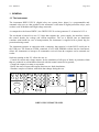
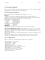
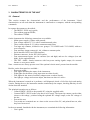
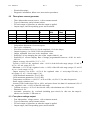
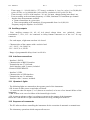
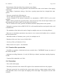
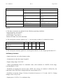
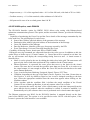
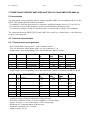
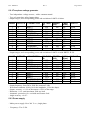
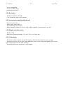
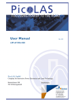
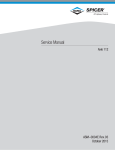
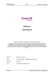
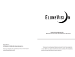
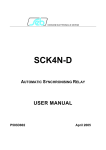
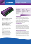
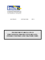
DOC.SIE62153
DATE: 08/12/2008
REV. 1
INSTRUMENT DRTS.3 PLUS
FOR TESTING PROTECTIVE RELAYS,
ENERGY METERS AND TRANSDUCERS
Doc. SIE62153
REVISIONS
N.
PAGE
1
All
Rev. 1
SUMMARY
DATE
08/12/2008 Issued
Page 2/24
VISA
Lodi
Doc. SIE62153
Rev. 1
Page 3/24
1 GENERAL ....................................................................................................................................................................................... 4
1.1 THE INSTRUMENT ......................................................................................................................................................................... 4
1.2 OPTIONS......................................................................................................................................................................................... 5
1.3 TDMS, THE SOFTWARE FOR DRTS.3 PLUS ........................................................................................................................... 5
2 APPLICABLE STANDARDS .................................................................................................................................................... 6
2.1 ELECTROMAGNETIC COMPATIBILITY........................................................................................................................................ 6
EMISSION....................................................................................................................................................................................6
IMMUNITY..................................................................................................................................................................................6
1.2 LOW VOLTAGE DIRECTIVE .......................................................................................................................................................... 6
3 CHARACTERISTICS OF THE UNIT .................................................................................................................................... 7
3.1 GENERAL ..................................................................................................................................................................................... 7
3.2 THREE PHASE CURRENT GENERATOR ...................................................................................................................................... 8
3.3 FOUR PHASE VOLTAGE OUTPUT ................................................................................................................................................ 8
3.4 FOURTH VOLTAGE OUTPUT V4.................................................................................................................................................. 9
3.5 A NGLES...................................................................................................................................................................................... 10
3.6 OUTPUT FREQUENCY................................................................................................................................................................ 10
3.7 LOW VOLTAGE OUTPUTS......................................................................................................................................................... 11
3.8 TIME MEASUREMENTS............................................................................................................................................................. 11
3.9 A UXILIARY OUTPUTS................................................................................................................................................................ 12
3.10 INTERFACE CONNECTIONS ..................................................................................................................................................... 12
3.11 OPERATOR’S LIGHTS............................................................................................................................................................... 12
3.12 SEQUENCE OF COMMANDS..................................................................................................................................................... 12
3.13 TRANSIENT FILES REPRODUCTION........................................................................................................................................ 13
3.14 PROTECTIONS .......................................................................................................................................................................... 13
3.15 POWER SUPPLY........................................................................................................................................................................ 14
3.16 ENCLOSURE .............................................................................................................................................................................. 14
3.17 A CCESSORIES............................................................................................................................................................................ 14
3.18 W EIGHT AND DIMENSIONS..................................................................................................................................................... 14
4 DRTS.3 PLUS OPTIONS ............................................................................................................................................................. 15
4.1 OUTPUT VOLTAGE ...................................................................................................................................................................... 15
4.2 OPTIONAL CURRENT AND VOLTAGE MEASUREMENTS.......................................................................................................... 15
4.3 HIGH PRECISION MODEL ........................................................................................................................................................... 15
4.4 BATTERY SIMULATOR................................................................................................................................................................ 16
4.5 IEC61850 OPTION; CODE PII80156......................................................................................................................................... 17
4.6 RELAY CONNECTION CABLES; CODE ZII15156...................................................................................................................... 18
4.7 GPS SYNCHRONIZER; CODE ZII10161 .................................................................................................................................... 18
4.8 SHA-6 ENERGY METERS UNIVERSAL SCANNING HEAD; CODE ZII20162........................................................................... 19
4.9 IN2-CDG CURRENT BOOSTER FOR 1 A RATED RELAYS AND FOR THE CDG RELAY OF GE; CODE ZII99156 ............. 20
4.10 TRANSIT CASE .......................................................................................................................................................................... 20
4.11 M AINS SYNCHRONISER OPTION, CODE PII24156................................................................................................................. 20
5 THREE PHASE CURRENT AMPLIFIER AND TWO VOLTAGE AMPLIFIER AMIV-66 ................................ 22
5.1 INTRODUCTION........................................................................................................................................................................... 22
5.2 TECHNICAL CHARACTERISTICS ................................................................................................................................................ 22
5.2.1 Three phase current generator...................................................................................................................................... 22
5.2.2 Two phase voltage generator......................................................................................................................................... 23
5.2.3 Power supply ..................................................................................................................................................................... 23
5.2.4 Enclosure ........................................................................................................................................................................... 24
5.2.5 Accessories supplied with the unit ................................................................................................................................ 24
5.2.6 Weight and dimensions ................................................................................................................................................... 24
5.2.7 Protections ........................................................................................................................................................................ 24
Doc. SIE62153
Rev. 1
Page 4/24
1 GENERAL
1.1 The instrument
The instrument DRTS.3 PLUS (digital relay test system, three phase) is a programmable and
automatic relay test set, that permits for the automatic verification of digital protection relays, such
as those used in Medium and High voltage networks.
As compared to the former DRTS.3, the DRTS.3 PLUS version generates 15 A instead of 12.5 A.
The test bench is housed in a case 3 U high, that contains: the power supply, the interface circuits,
the control boards, the voltage and current amplifiers. The set is housed into an aluminium
container with handle for ease of transportation; the instrument is supplied with a plastic bag for
protection during transit.
The instrument operates in connection with a computer, that controls it via the RS232 serial port or
the USB port. The firmware FWH6, contained in a FLASH EPROM resident into the instrument,
allows the instrument to interpret all commands received from the computer and to transmit test
results.
Software running on the P.C. allow the user to:
. Control all current and voltage outputs, for the simulation of all types of faults: in particular, faults
that are produced on a distribution network with the neutral connected to ground;
. Change the output in a ramp or step mode;
. Define the state of inputs and outputs between two fault simulations;
. Simulate complex evolution, with faults that change during the test.
OK
0
10 V ---
C4
C8
A4
V1
C3
C7
A3
V2
I1
I4
I2
I5
!
250 V~
ERR
0
20 mA---
V0/V4
ON
20 A~
ANALOG INPUT
RTS.3
DRTS-6
C2
C6
A2
C1
C5
A1
V3
I3
I6
RS232
VN
!
IN
125/300 V ~
C
IMP1
V~
EXT. AMP.
T16A 250V
IMP2
V---
V~
250 V ~
IN
15 A ~
250 V~5 A
C
AUTOMATIC RELAY TESTING
AND MEASUREMENT SYSTEM
!
260 V--110/230 V~ 50/60 Hz
DRTS.3 PLUS FRONT PANEL
Doc. SIE62153
Rev. 1
Page 5/24
1.2 Options
There are many options available for DRTS.3 PLUS: they are described in detail on chapter 4.
1.3 TDMS, the software for DRTS.3 PLUS
All controls of the instrument are performed by the software TDMS, which is described in
document MSE10015.
Doc. SIE62153
Rev. 1
Page 6/24
2 APPLICABLE STANDARDS
The test set DRTS.3 PLUS and optional modules conform to the EEC directives regarding
Electromagnetic Compatibility and Low Voltage instruments.
2.1 Electromagnetic Compatibility
Directive no. 2004/108/EC. Applicable Standard : EN61326-1 + A1 + A2.
EMISSION
- EN 61000-3-3: Limitation of voltage fluctuations and flicker. Acceptable limits: basic.
- CISPR16 (EN 55011 class A): Limits and measurement methods of radio-electric disturbances for
industrial, medical and scientific instruments at radio-electric frequencies.
Acceptable limits for conducted emission:
. 0.15-0.5 MHz:
79 dB pk; 66 dB avg.
. 0.5-5 MHz:
73 dB pk; 60 dB avg.
. 5-30 MHz:
73 dB pk; 60 dB avg.
Acceptable limits for radiated emission:
. 30-230 MHz:
40 dB (30 m)
. 230-1000 MHz:
47 dB (30 m)
IMMUNITY
- EN 61000-4-2: Immunity tests for ESD. Test values: 8 kV in air; 4 kV in contact.
- EN 61000-4-3; Immunity tests for radio frequency interference. Test values (f= 900 ± 5 MHz):
field 10 V/m, modulated AM 80%; 1 kHz
- EN 61000-4-4; Immunity tests for high speed transients (burst). Test values: 2 kV peak; 5/50 ns.
- EN 61000-4-5; Immunity tests for surge. Test values: 1 kV peak differential mode; 2 kV peak
common mode; 1.2/50 us.
- EN 61000-4-6: immunity to low-voltage sinusoidal waveform. Test values: 0.15-80 MHz, 3 Vrms,
80% AM 1 kHz.
- EN 61000-4-8: Immunity tests for low frequency magnetic fields. Test values: 30 Arms/m.
- EN 61000-4-11: Immunity test for power supply drops. Test value: 1 cycle; 100% drop.
1.2 Low voltage directive
Directive n. 2006/95/EC. Applicable standard: CEI EN 61010-1. In particular:
- Dielectric Rigidity: 1.4 kV, 1 minute.
- Isolation resistance: > 2 MOhm.
- Earth resistance : < 0.1 Ohm.
- Dispersion current: < 5 mA.
- Inputs/outputs protection: IP 2X - IEC 60529.
- Operating temperature: 0 - 50°C; storage: -25°C to 70°C.
- Relative humidity : 5 - 95%, not condensing.
- Vibration: IEC 68-2-6 (20 m/s^2 at 10 – 150 Hz);
- Shock: IEC 68-2-27 (15 g; 11 ms; half- sine).
- Altitude: less than 2000 m.
Doc. SIE62153
Rev. 1
Page 7/24
3 CHARACTERISTICS OF THE UNIT
3.1 General
This section resumes the characteristic and the performances of the instrument. Listed
characteristics are all used when the instrument is connected to a computer, with the corresponding
commands.
In separate documents are described:
- The DRTS.3 PLUS user's guide;
- The resident program FWH6;
- The software TDMS.
On the instrument the following connections are available:
- Mains power supply (2 phase with ground);
- Four voltage outputs V1-V4, with a common neutral point;
- Three current outputs I1-I3, with a common neutral point;
- Ten input trip contacts, divided in two groups C1-C4+IMP1 and C5-C8+IMP2, with two
zero references;
- Four auxiliary output contacts A1-A4, without a common point;
- Serial interface RS232 and USB interface;
- Ethernet connector, for the IEC61850 option;
- Four measurement inputs: two for currents (low and high) and two for voltages (low and
high), for the optional board;
- The EXT. AMPL. female connector with low-power analog signals output, for external
booster or zero-power mode.
Note: connectors are always present even if the optional circuits aren’t present into the module.
Besides, on the front panel are available :
- Power-on switch;
- Four lights indicating the status of the instrument;
- Eight lights for the status of trip input (turn on when closed);
- Four lights for the status of auxiliary outputs (turn on when closed);
- One light per voltage and current output, that turns on when it is active.
When the instrument is turned on it performs a self-diagnostic check of all of the logic and analog
circuits. During the use, the instrument watches continuously the outputs, checking that they do not
deviate from the nominal.
The principal operation are as follows:
- Connect DRTS.3 PLUS to the portable PC, using the supplied cable;
- Connect DRTS.3 PLUS to the relay that is to be tested. The input trip contacts can be either
clean or with voltage, polarized using the optional DC voltage output, or the DC voltage of
the site;
- Execute the test;
- Test results are examined one at a time on the screen of the PC, and printed later on, after
they have been saved.
In the user manual, furnished with the instrument, are contained the following information:
- User's guide;
Doc. SIE62153
Rev. 1
Page 8/24
- Electrical drawings;
- Diagnostic information, failure area, intervention procedures.
3.2 Three phase current generator
-
Three independent current sources, with a common neutral.
Type of connection: safety banana sockets.
For each output, a light turns on when the output is applied.
Output ranges, and corresponding power and resolution.
RANGE OUTPUTS CONNECTION CURRENT
(A)
1
2
3
4
5
3
3
3
1
1
X
X
X
X
X
DIRECT
DIRECT
DIRECT
3 IN PARALLEL
TWO IN SERIES
0…15
0…1.5
0…0.15
0…45
0…15
POWER Z MAX
(VA)
(Ohm)
100
300
200
0.44
0.44
0.44
0.15
0,88
RESOL.
230 µA
23 µA
2 µA
690 uA
230 µA
Independent adjustment of current outputs.
Duty cycle: continuous.
Waveform resolution: 28 bit (16 for the amplitude, 12 for the shape).
Output frequency: 0 to 2 kHz; 5 kHz on reproductions.
Output adjustable from zero to the maximum value.
Possibility of step changing the value of the output within 0.1 ms.
Possibility of current ramping. Rate of change programmable between ± 0.001 A/s and ±
999 A/s.
- Output accuracy; 40 to 60 Hz; 23 °C ± 5 °C.
. Typical: ± 0.05% of the regulated value ± 0.01% of the full scale range (ranges 1.5 and 15
A), or ± 0.5 mA (range 0.15 A).
. Maximum: ± 0.1% of the regulated value ± 0.02% of the full scale range (ranges 1.5 and 15
A), or ± 1 mA (range 0.15 A).
- Output accuracy; 0 to 40 Hz.: ± 0.5% of the regulated value ± 1 mA (range 150 mA); ± 4
mA (range 1,5 A); ± 10 mA (range 15 A).
- 1 kHz maximum attenuation: 3% (0,3 dB).
- 2 kHz maximum attenuation: 5% (0,5 dB).
- Temperature coefficient: ± 0,01%/°C, at 50 to 60 Hz; ± 0,02%/°C, for other frequencies.
- Power supply variation: zero.
- Accuracy with: burden from 30% to 100%, and power factor less than 0.8: maximum 0,2% of
the regulated value ± 0.05% of the full scale range.
- Gradient accuracy: ± 0.5% of the selected value, with minimum rate of 200 mA/s.
- Distortion: 0.1% .
- Automatic protection for overloads (including open circuit). In this case, the output is
taken to zero and the ! LED turns on.
-
3.3 Four phase voltage output
- Four independent voltage sources, with a common neutral.
- Type of connection: safety banana sockets.
- For each output, a light turns on when the output is applied.
- Output ranges, and corresponding power and resolution.
Doc. SIE62153
RANGE OUTPUTS
1
2
3
4
5
6
4X
3X
3X
3X
1X
1X
1
1
2
3
4
5
4X
3X
3X
3X
1X
1X
Rev. 1
CONNECTION
VOLTAGE
(V)
Page 9/24
POWER
(VA)
DIRECT
0…125
85
DIRECT
0…125
100
DIRECT
0…12,5
DIRECT
0…1
2 IN SERIES
0…250
200
2 IN PARALLEL
0…125
200
OPTIONAL 300 V OUTPUT
DIRECT
0…300
85
DIRECT
0…300
100
DIRECT
0…125
100
DIRECT
0… 12.5
2 IN SERIES
0…600
200
2 IN PARALLEL
0…300
200
Z MAX
(Ohm)
RESOLUT.
200
160
160
160
320
80
1.9 mV
1.9 mV
190 µV
19 µV
3.8 mV
1.9 mV
1125
900
160
160
1800
450
4.6 mV
4.6 mV
1.9 mV
190 µV
9.2 mV
4.6 mV
- Independent adjustment of voltage outputs.
- Duty cycle: continuous.
- Waveform resolution: 28 bit (16 for the amplitude, 12 for the shape).
- Output frequency: 0 to 2 kHz; 5 kHz on reproductions, for the 125 V output; 0 to 700 Hz, 5
kHz on reproductions, for the optional 300 V output.
- Output adjustable from zero to the maximum value.
- Possibility of step changing the value of the output within 0.1 ms.
- Possibility of ramping the voltage. Rate of change programmable between ± 0.001 V/s and ±
999 V/s.
- Output accuracy, 40 to 60 Hz; 23 °C ± 5 °C.
. Typical: ± 0.05% of the regulated value ± 0.01% of the full scale range (ranges 12.5, 125 and
300 V), or ± 1 mV (range 1 V).
. Maximum: ± 0.1% of the regulated value ± 0.02% of the full scale range (ranges 12.5, 125
and 300 V), or ± 2 mV (range 1 V).
- Output accuracy; 0 to 40 Hz.: ± 0.5% of the regulated value ± 2 mV (range 1 V); ± 10 mV
(range 12,5 V); ± 50 mV (range 125 V); ± 120 mV (range 300 V).
- 700 Hz maximum attenuation (300 V model): 1% (0,1 dB).
- 1 kHz maximum attenuation: 3% (0,3 dB).
- 2 kHz maximum attenuation: 5% (0,5 dB).
- Temperature coefficient: ± 0,01%/°C, at 50 to 60 Hz; ± 0,02%/°C, for other frequencies.
- Power supply variation: zero.
- Accuracy with: burden from 30% to 100%, and power factor less than 0.8: maximum 0,2% of
the regulated value ± 0.05% of the full scale range.
- Voltage gradient accuracy: ± 0.5% of the selected value, with minimum gradient of 200
mV/s.
- Distortion: 0.1% total maximum, with any load.
- Automatic protection for overloads (short circuit included). In this case, the output is taken
to zero and the ! LED turns on.
3.4 Fourth voltage output V4
- The fourth voltage output can be selected via software to act as:
. Fourth voltage output V4;
Doc. SIE62153
Rev. 1
Page 10/24
. Zero-sequence component VO of the other three voltages V1, V2 V3. Via software the output can
be selected to be: VO = (V1+V2+V3)/3 or VO = (V1+V2+V3)/1.73 (bolded stays for vector sum).
Note that with last two selections the zero sequence component is limited to 125 V (or 300 V if the
optional range is available).
- For the zero-sequence output, the following specifications apply.
. Range: 125 V – Optionally 300 V.
. Output accuracy: ± 0.5% of the value ± 0.1% of the range.
3.5 Angles
- All angles are referred to the same absolute reference.
- Possibility to set independently the angle of all outputs: V1; V2; V3; V4; I1; I2; I3; I4; I5; I6, in
the field between zero and ± 360° (phase angle).
- Possibility of slewing all the angles. Variation range: 0.1°/s to 999 °/s.
- Angle resolution: 0.01°.
- Angle accuracy (40 to 60 Hz): typical ± 0.02°; maximum ± 0.1°.
- Angle accuracy (5 to 40 Hz): maximum ± 1°.
- Angle accuracy (60 to 2 kHz): maximum ± 5°.
3.6 Output frequency
- Possibility of selecting the output frequency between 0.0000 and 1999.9999 Hz.
- Possibility to set the fault frequency on:
. All outputs;
. V1 only;
. Voltages V1-V2 -V3;
. I1 plus V1 – V2 – V3;
. All outputs unless V4;
. V1 and V2.
With all selections unless the first one, not selected outputs stay at pre-fault frequency.
- Maximum frequency error: 0.5 ppM (25 uHz @ 50 Hz).
- Temperature drift of the oscillator frequency: 0,1 ppM/°C.
- Resolution: 0.1 mHz.
- Possibility of step switching the output frequency, separately or together with the amplitude
change.
- Possibility of slewing the frequency, with a slope from 0.001 Hz/s to 999.999 Hz/s. Resolution:
0.001 Hz/s.
- Slew accuracy: 0.01 Hz/s, with a minimum of 0.1 Hz/s.
Doc. SIE62153
Rev. 1
Page 11/24
3.7 Low voltage outputs
The purpose of these low voltage outputs is to allow testing newest protection relays with low
voltage inputs, and to control the external boosters, thus providing the following features:
. to increase the power output, or:
. to control six currents or six voltages at the meantime.
A connector carries six analog signals, that correspond to the three voltages and to the three
currents. When the supplied male connector is fit into the socket, power outputs are automatically
cut.
- Number of outputs: 6.
- Connection: 23 way connector.
- Full range voltage output: 7.26 Vrms. *
- Full range current output: 0.726 or 7.26 Vrms. *
- Output current: 5 mA max.
- Resolution: 0.43 mV or 0.043 mV. *
- Accuracy: 0.1% of range. *
- Distortion: 0.1%. *
- Frequency bandwith
- up to 10kHz for 6 channels
- up to 20kHz for 3 channels: V1,V2 and I1. The others are disabled.
* In the range 40 to 60 Hz.
- Output accuracy; 0 to 40 Hz.: ± 0.2% of the regulated value ± 0.04% of the full scale range.
- 700 Hz maximum attenuation (300 V model): 1% (0,1 dB).
- 1 kHz maximum attenuation: 3% (0,3 dB).
- 2 kHz maximum attenuation: 5% (0,5 dB).
3.8 Time measurements
- Digital inputs: 10 inputs, either clean or with voltage, from 4.5 to 600 V DC(24 to 425 V a.c.),
divided in two groups of five input each, with two common points isolated at 1 kVac. This
feature allows the measurement of polarized trip contacts with two different zeroes that can’t be
put in common. All of them perform time measurements; two (called IMP1 and IMP2) measure
also the time taken by a programmable number of impulses.
- Connections: to safety banana sockets, marked C1 - C4 and IMP1; C5 - C8 and IMP2.
- For each input, a light turns on when the input is closed (or the voltage applied).
- Selection of the type of input: Voltage clean; 5 V; 24 V; 48 V; 100 V; software controlled. The
selection clean/voltage is displayed by two warning lights (one per group) : the light turns on if
the group is under voltage.
- Input impedance: 1 MOhm.
- Selection of the input debounce duration, from 0 us to 2 ms, in 64 steps of 32 us each, program
controlled.
- For all selections, inputs are protected against voltages up to the maximum specified above.
- Indication of the state of the inputs by lights mounted on the operator panel.
- Selection N.O./N.C., independent for each input.
- Time measurements available:
• Timing from the start of the test (injection) until the change of state or the reset of the
selected input;
• Timing from the change of state or the reset of an input in respect to any other input.
Doc. SIE62153
-
-
Rev. 1
Page 12/24
Timer range: 0 - 999,999.9999 s (277 hours); resolution: 0.1 ms. In cycles: 0 to 50,000,000
cycles (50 Hz), or 0 to 60,000,000 cycles (60 Hz); resolution: 0.005 cycles (50 Hz).
Timer accuracy: 0.025% of the measure ± 0.1 ms, for input changes lasting more than 1 ms.
Event recording, at the maximum frequency of 1 kHz; maximum 512 transitions per channel.
Impulse time measurements available:
• Count of transitions in a given time;
• Time corresponding to N transitions; N programmable from 1 to 9,999,999.
Frequency range for impulses: 0 to 50 kHz.
3.9 Auxiliary outputs
- Four auxiliary contacts (A1, A2, A3, A4), timed, voltage clean, not polarized, whose
termination C, N.O., N.C. are connected to safety banana connectors or to the A+C 28 way
connector.
- For each output, a light turns on when it is closed.
- Characteristics of the contacts with a resistive load:
. A.C.: 300 V; 8 A; 2400 VA;
. D.C.: 300 V; 8 A; 250 W.
- Range of programmable delay: from 0 to 999.99 s.
3.10 Interface connections
- Interface 1: RS232.
- Characteristics of RS232 interface:
. Transmission rate: 57,600 baud.
. Serial interface cable: 2 meters, included.
. Protocol: BUSY/READY.
- Interface 2: USB.
- Characteristics of USB interface:
. Transmission rate: 3x minimum.
. Interface cable: 2 meters, included.
3.11 Operator’s lights
- The following lights are mounted on the operator panel of the instrument:
. OK: it turns on after power-on and after self-check.
. !: it turns on when an output (V or I) detects an overload, or in case of an internal failure of the
instrument.
. ERR: it turns on in case of a failure of the internal logic circuits.
. ON: it turns on whenever there is a voltage or current on the outputs of the instrument.
Below the USB interface a light confirms that data are being exchanged with the PC.
3.12 Sequence of commands
- The PC software allows controlling the instrument for the execution of automatic or manual tests.
- The elementary operations which compose all tests are:
Doc. SIE62153
Rev. 1
Page 13/24
. Measurement of the time delay from parameters step change;
. Search of the threshold, slewing parameters and memorize the value at the instant of the tripping
of the input;
. Step change of parameters during a fixed time, reporting inputs that have changed their state
(pause).
- Tests are executed in the following way:
. The PC defines the parameters to inject or vary;
. At the command of the operator, parameters are transmitted to DRTS.3 PLUS by the serial
interface;
. DRTS.3 PLUS generates the specified values, waits for the trip of the selected input contacts, and
then transmits the results to the PC by the same serial interface;
. The PC examines the results, performs calculations and then displays them to the operator.
- During the execution of the test DRTS.3 PLUS is self controlled and does not depend on the serial
communication.
- The simulation of the fault can be made of single or multiple tests (case of evolving failures).
- Between two simulations parameters may return to zero, return to the healthy value or maintain
the last injected value.
- Maximum number of elementary tests (cycles) in a multiple test: 49.
- Duration of the cycle: from 1 ms to 999999.9999 s;
- Accuracy of the cycle duration: 0.2 ms.
- Delay between two cycles: 1 ms maximum.
3.13 Transient files reproduction
- Possibility to reproduce a fault that has been recorded with a COMTRADE format, by means of
the software R-PRO.
- Maximum recording dimension: 16 word; 64 kWord per channel; maximum sampling frequency
50 kHz.
- Transient files bandwidth: 0 to 5 kHz.
3.14 Protections
- Fuse on the mains supply.
- Electronic protections on the internal DC supplies of the instrument and alert to the program.
- Electronic protection for overload on the current (open circuit) or voltage outputs (short circuit),
with immediate release of the output and lighting of the alarm light. The program resets the fault
condition.
Doc. SIE62153
Rev. 1
Page 14/24
- Electronic protection in case of counter- feed of voltage outputs. In this instance, the ! alarm light
turns on.
- Electronic protection sensing if the test set is not properly grounded: in this instance, the operator
is warned.
- Protection against over-temperature, on all outputs.
- Diagnostic messages for the setting of wrong data, mistakes on the inputs etc.
3.15 Power supply
- Mains power supply: 90 to 132 and 180 to 264 V a.c., sinusoidal, single phase.
- Frequency: 47 to 63 Hz.
- Power consumption:
. at rest: less than 150 W;
. maximum load: 1200 W.
3.16 Enclosure
- Instrument: 3U rack.
- Case: Aluminum, with carrying handle. The instrument may be operated in the horizontal or
vertical positions.
3.17 Accessories
The following items are supplied with the DRTS.3 PLUS :
. Protection bag;
. Mains supply cable;
. Serial and USB cables;
. Relay connection cables kit: 12 in all, 4 red, 4 black, 2 blue, 2 yellow; length 2 m, cross section 1
sq. mm.
. Ground connection cable: 2 m, yellow/green, terminated with crocodile clamp.
3.18 Weight and dimensions
- Weight: 18 kg.
- Dimensions: 170 (h) x 470 (w) x 430 (d) mm.
Doc. SIE62153
Rev. 1
Page 15/24
4 DRTS.3 PLUS OPTIONS
The first five options are to be specified at order.
4.1 Output voltage
The output voltage can be up to 300 V instead of 125 V; specifications are given in the voltage
outputs paragraph. This option is to be specified at order.
4.2 Optional current and voltage measurements
Optionally it is possible to measure currents and voltages. Connections: to safety banana plugs.
- DC Current measuring Input, Low
. Measuring range: ± 20 mA
. Resolution: 10 nA.
. Accuracy: 0.02% of range ± 0.01% of value.
. Temperature drift: : ± 0.01%/°C of value ± 0.03%/°C of range
- DC Voltage measuring input, Low
. Measuring range ± 10 V
. Resolution: 10 µV.
. Accuracy: 0.02% of range ± 0.01% of value.
. Temperature drift: : ± 0.005%/°C of value ± 0.02%/°C of range
- AC/DC Current measuring Input, High
. Measuring range: ± 20 A
. Resolution: 10 mA.
. AC accuracy: 0.2% of range ± 0.1% of value.
. Temperature drift: : ± 0.05%/°C of value ± 0.01%/°C of range
. DC accuracy: 0.1% of range ± 0.1% of value.
. Temperature drift: : ± 0.05%/°C of value ± 0.02%/°C of range
- AC/DC Voltage measuring input, High
. Measuring range ± 250 V
. Resolution: 10 mV.
. AC accuracy: 0.1% of range ± 0.1% of value.
. Temperature drift: : ± 0.05%/°C of value ± 0.01%/°C of range
. DC accuracy: 0.05% of range ± 0.05% of value.
. Temperature drift: : ± 0.05%/°C of value ± 0.02%/°C of range
NOTE: AC specification applies to frequencies between 48 and 62 Hz.
This option is to be specified at order.
4.3 High Precision model
This option has enhanced characteristics with respect to the standard model. This model is
conceived for the test of class 0.2 energy meters. The following table summarizes the performances
of the RRTS.3 PLUS-HP (High Precision) version with respect to the standard one.
Doc. SIE62153
OUTPUT CURRENT
OUTPUT VOLTAGE
PHASE ANGLE
POWER; SEE TABLE
Rev. 1
Page 16/24
STANDARD DRTS.3 PLUS
Typical: ± 0.05% ± 0.01% of
range
Maximum: ± 0.1% ± 0.02% of
range
Typical: ± 0.05% ± 0.01% of
range
Maximum: ± 0.1% ± 0.02% of
range
Typical: ± 0.02°
Maximum: ± 0.1°
Typical: ± 0.05%
Maximum: ± 0.2%
DRTS.3 PLUS-HP
Typical: ± 0.02% from 0.1 to 15
A
Maximum: ± 0.05% from 0.1 to
15 A
Typical: ± 0.02% from 50 to
300 V
Maximum: ± 0.05% from 50 to
300 V
Typical: ± 0.01°
Maximum: ± 0.02°
Typical: ± 0.05%
Maximum: ± 0.1%
NOTES
1) The above accuracies are obtained in the following operating conditions:
. Output frequency: 40 to 60 Hz;
. Temperature: 20 °C to 25°C;
. Power supply: 210 to 240 V;
. Burden: less than 30% of the maximum.
2) The rated power accuracy applies to p.f. = 1; the accuracy at other p.f. is shown here below.
p.f.
1
Max. error for std. DRTS.3 0,2
PLUS, %
Max error for DRTS.3 PLUS - 0,1
HP, %
0,8
0,25
0,5
0,27
0,125 0,135
0,1
1,1
0
Infinite
0,55 Infinite
3) The rated power accuracy applies for currents greater than 0,1 A and voltages greater than 10 V.
4.4 Battery simulator
- Output connection: two safety banana sockets.
- A light turns on when the output is applied.
- Output voltage range: 260 V D.C..
- Output programmable from 0 to maximum value, with resolution of 1/2047rd of the range,
corresponding to 63 mV.
- Possibility of stepping the selected value. NOTE: the velocity of variation is affected by the
capacitance of the load, that is charged with the current output of 2 A.
- Possibility to ramp the voltage. Velocity of variation is between ± 0.1 V/s and ± 999 V/s. Voltage
changes occurs every 10 ms.
- Output power: 100 W or 2 A; continuous duty.
Doc. SIE62153
Rev. 1
Page 17/24
- Output accuracy: ± 1% of the regulated value ± 0.1% of the full scale, with load of 25% to 100%.
- Gradient accuracy: ± 1% of the nominal, with a minimum of ±200 mV/s.
- Self protected in case of an overload greater than 100 W.
4.5 IEC61850 option; code PII80156
The IEC61850 Interface option for DRTS3 PLUS allows relay testing with Ethernet-based
substation communication protocol. The option, and the associated software, provides the following
features:
. Capability of monitoring the Goose List and the Goose details of the messages transmitted by the
relay under test. The grid displays for each Goose:
• Source Mac Address: physical address of the generator of the message
• Destination Mac Address: physical address of the destination of the message
• Goose ID: Identifier of the Message
• Data Set Reference: Identifier of the type of message created by the IED
• Event Time Stamp: Universal Time that identifies the Goose
. Capability of filtering Gooses, based upon IED or TIMESTAMP;
. During the test, trip commands are connected from the relay to the test set. In addition to this, the
option allows to define up to 8 Virtual Contacts, i.e. Gooses that will be captured in real time: the
test set will measure and display the corresponding timing from test start. A virtual contact is
identified by a:
• Name: it can be given by the user by editing the relative box in the grid. The same name will
appear in the lower frame that represent the Trip condition for the Virtual contact.
• Dataset Reference: it represents the exact goose that serves as the basis for the virtual
contact. The same device can and does produce more than one Goose ID, so in order to set
the virtual contact it is not enough to define the Goose ID, but the selection has to be made
on the Dataset Reference.
• Type: it can be Boolean, BitString, Unsigned, Signed, Float or UTCTime.
• Condition: depending on the type of the data it can be: Equal to, Less than, Greater than or
Not Equal to. It is set by default to Equal to, but it can be changed according to the data
type. Select the appropriate condition form the menu that appears when clicking on the
condition column.
• Value: together with the condition field, it defines the actual condition of the Virtual
Contact. In case of data type Boolean, it can only assume value True or False.
• Time: represents the actual ‘trip time’ of the virtual contact, or the time interpreted from the
goose that the device produces when the condition is verified. It cannot be modified, it is
automatically set by the software when a test is performed and a virtual contact has tripped.
The Ethernet connector type RJ-45 for the IEC61850 Interface is mounted directly on the front
panel of the DRTS3 plus. The option is to be specified at order. NOTE: with this option, if the
booster is present the serial interface is not available.
Doc. SIE62153
Rev. 1
Page 18/24
With the option are also provided two ETHERNET cables: one for the connection to a switch on the
Station bus; the other one for the direct connection to the relay.
The option is exclusive of external boosters option.
This option is to be specified at order.
4.6 Relay connection cables; code ZII15156
This option includes 29 cables, with different colours, with banana plugs, 2 m long, cross section
1.5 sq. mm unless for current connections, that allow for the connection to the relay under test to the
following sockets:
- Current outputs (8 cables, cross section 6 sq. mm);
- Voltage outputs (5 cables; 4 red and 1 blue for the neutral);
- Auxiliary DCsupply (2 cables; 1 red and 1 black);
- Trip inputs (10 cables; 8 red and 2 black for the common);
- Auxiliary outputs (4 cables; 2 black and 2 yellow).
4.7 GPS synchronizer; code ZII10161
The GPS synchronizer is an external module that allows to synchronize test start of two RTS.3.
Features are:
. 1 digital output 0-24 Vdc, for synchronisation.
. 1 selector to program the following pulse intervals: 5 s; 10 s; 20 s; 30 s; 40 s; 60 s.
. Maximum timing error with respect to nominal: 2 us.
. Lights to confirm: power-on; Locked; Pulse available.
. 1 START and STOP push-button.
. Power supply: 110/220 Vac.
. The option includes:
- The antenna;
- An extension cable for the antenna, 20 m long;
- Two cables, red and black, 2 m long, with banana terminations, for the connection to the
test set trip input;
- The power supply cable.
. Weight: 1.7 kg.
. Dimensions: width = 150 mm; height = 100 mm, depth = 240 mm.
. Realisation: aluminium case.
Two test sets synchronized with GPS produce the maximum error of 50 us.
Doc. SIE62153
Rev. 1
PULSE
Page 19/24
GPS SYNCHRONIZER
20
30
10
1 pps
START/STOP
40
5
60
GPS
PULSE INTERVAL
(seconds)
LOCKED
GPS ANTENNA
T0,5A 250V
PULSE
100-240V~ 50/60Hz 5W
00
GPS front and rear view
4.8 SHA-6 energy meters universal scanning head; code ZII20162
SHA-6 is a scanning head that eases the test of energy meters. It is an universal scanning head
because it can be used both with LED impulse electronic meters and Ferraris rotating disk meters;
selection is performed via a switch located on the scanning head. In addition to this, a knob allows
to adjust the sensitivity of the head.
With rotating disk the sensor uses a green light beam that optimizes the recognition of any type of
mark.
With LED recognition the following specification applies:
. Impulse duration: more than 60 us;
. With an LED signal having a space ratio 1:2, the frequency must be less than 500 Hz.;
. Light wavelength: 500 to 960 nm (red).
The option includes:
- The support that allows to keep the scanning head in front of the energy meter: maximum height
175 mm;
Doc. SIE62153
Rev. 1
Page 20/24
- The cable, 2 m long, from the scanning head to the DRTS;
- The power supply transformer, for the power of 220 Vac, to supply the scanning head.
- Two safety banana plugs for the connection to RTS.3.
4.9 IN2-CDG current booster for 1 A rated relays and for the CDG relay of GE; code
ZII99156
With DRTS.3 PLUS the full power of 100 VA is available only at the current of 15 A. This is good
for the test of relays with the nominal current of 5 A; if relays are rated 1 A the available power can
be not adequate to perform the test. In addition to this, relay CDG of GE has very low current
settings.
The option IN2-CDG solves this problem, by means of a set of three current transformers, with the
following characteristics:
. Primaries: 12.5 A and 15 A;
. Secondaries: 0.5 A; 1 A; 2.5 A; 5 A;
. Nominal power: 100 VA;
. Current ratio error: 0.2.
- Case: plastic.
- Connections:
. Four primary side sockets (I1, I2, I3, IN);
. Three independent outputs, with one phase socket and 2 zero sockets;
. Ease of connecting outputs in star or delta configuration.
. For the single phase test of the CDG relay it is possible to have three times the above power,
connecting current outputs in series.
The option includes four connecting cables to DRTS.3 PLUS current outputs, 1 m long, 2.5 sq. mm
cross section. Outputs are do not have a common neutral; this eases the star or delta connection.
Included is a bridge for star connection.
NOTE: the software takes into account the transformers ratio.
4.10 Transit case
The protection of DRTS.3 PLUS from delivery problems is provided by this robust transit case, that
features the following.
- Molded-case construction;
- Handle on the top;
- Dimensions: 24 x 57 x 58 cm.
4.11 Mains synchroniser option, code PII24156
The option is made of a plug that fits into the mains, and that has two banana sockets for the
connection to the test set counting input. The purpose is to synchronize the outputs of two test sets
to the mains: as the synchronisation is repeated every 2 minutes, the test set stays locked to the
mains for the infinity.
The option includes a circuit that squares the sinusoidal mains waveform; the isolated output is a
square-wave with an amplitude of 18 V nominal, running at the mains frequency.
Doc. SIE62153
Rev. 1
Page 21/24
There are two instances where the option can be necessary:
. Generating a current or voltage into a device that is also taking a signal from the mains;
. Synchronising two test sets to the mains, and then using them to test line differential relays.
Doc. SIE62153
Rev. 1
Page 22/24
5 THREE PHASE CURRENT AMPLIFIER AND TWO VOLTAGE AMPLIFIER AMIV-66
5.1 Introduction
The three phase current amplifier and two voltage amplifier AMIV-66 is an additional device to the
RTS.3. This option offers the following features:
. To multiply by three the three-phase test current by paralleling outputs (from 3x15 A to 3x45 A);
.To control six currents at the meantime, for the test of transformer protection relays;
. To control six voltages, so that it is possible to have 6 currents and 6 voltages at the meantime.
The connection between DRTS.3 PLUS and AMIV-66 is made by a control cable to be connected
to the 23 way connector.
5.2 Technical characteristics
5.2.1 Three phase current generator
- Three independent current sources, with a common neutral.
- Type of connection: safety banana plugs or 8 way connector (V+I).
- Output ranges, and corresponding power and resolution of AMIV-66 alone.
RANGE OUTPUTS CONNECTION CURRENT
(A)
1
2
3
4
5
3
3
3
1
1
X
X
X
X
X
DIRECT
DIRECT
DIRECT
2 IN SERIES
3 IN PARALLEL
0…30
0…3
0…0.3
0…30
0…90
POWER Z MAX
(VA)
(Ohm)
160
320
480
0.18
0.18
0.18
0.35
0.06
RESOLUT.
460 µA
46 µA
4.6 µA
460 µA
1.38 mA
- Output ranges, and corresponding power and resolution of AMIV-66 connected to DRTS3 PLUS.
RANGE OUT
1
2
3
4
5
6
7
3
3
3
3
3
3
3
3
3
1
X
X
X
X
X
X
X
X
X
X
CONNECTION
DIRECT
DIRECT
DIRECT
PARALLEL
PARALLEL
PARALLEL
ALL IN PARALLEL
CURRENT
(A)
0...15
0...30
0…1.5
0...3
0…0.15
0..0.3
0…45
0…4.5
0…0.45
0…135
POWER Z MAX
(VA)
(Ohm)
100
160
0.44
0.18
260
0.12
780
0.042
- Automatic range switch and independent range selection.
- Waveform resolution: 28 bit (16 for the amplitude, 12 for the shape).
- Output accuracy: ± 0.1% of the output ± 0.02% of the range.
- Distortion: 0.1% total maximum, with any load.
- Automatic protection for overloads.
- Angle accuracy: ± 0.05°.
RESOL.
230 µA
460 µA
23 µA
46 µA
2.3 µA
4.6 µA
690 µA
69 µA
6.9 µA
2.07 mA
Doc. SIE62153
Rev. 1
Page 23/24
5.2.2 Two phase voltage generator
- Two independent voltage sources, with a common neutral.
- Type of connection: safety banana plugs.
- Output ranges, and corresponding power and resolution of AMIV-66 alone.
RANGE OUTPUTS
1
2
3
4
5
2X
2X
2X
1X
1X
1
2
3
4
5
2X
2X
2X
1X
1X
CONNECTION
VOLTAGE POWER
(V)
(VA)
DIRECT
0…125
80
DIRECT
0…12,5
DIRECT
0…1
2 IN SERIES
0…250
160
2 IN PARALLEL
0…125
160
OPTIONAL 300 V OUTPUT
DIRECT
0…300
80
DIRECT
0…125
80
DIRECT
0… 12.5
2 IN SERIES
0…600
160
2 IN PARALLEL
0…300
160
Z MAX
(Ohm)
195
195
195
390
97
RISOLUT.
1125
195
195
390
97
4.6 mV
1.9 mV
190 µV
9.2 mV
4.6 mV
1.9 mV
190 µV
19 µV
3.8 mV
1.9 mV
- Output ranges, and corresponding power and resolution of AMIV-66 with DRTS3 PLUS.
RANGE OUTPUTS
1
2
3
4
5
6X
6X
6X
1X
1X
1
2
3
4
5
6X
6X
6X
1X
1X
CONNECTION
VOLTAGE POWER
(V)
(VA)
DIRECT
0…125
80
DIRECT
0…12,5
DIRECT
0…1
2 IN SERIES-PAR. 0…250
320
4 IN PARALLEL
0…125
320
OPTIONAL 300 V OUTPUT
DIRECT
0…300
80
DIRECT
0…125
80
DIRECT
0… 12.5
4 IN SERIES-PAR. 0…600
320
4 IN PARALLEL
0…300
320
- Output frequency: from DCto 2000 Hz; transient 5 kHz.
- Waveform resolution: 28 bit (16 for the amplitude, 12 for the shape).
- Output accuracy: ± 0.1% of the output ± 0.02% of the range.
- Distortion: 0.1% total maximum, with any load.
- Automatic protection for overloads and counter-feed.
- Angle accuracy: ± 0.05°.
5.2.3 Power supply
- Mains power supply: 90 to 264 V a.c., single phase.
- Frequency: 47 to 63 Hz.
Z MAX
(Ohm)
195
195
195
195
50
RISOLUT.
1125
195
195
195
50
4.6 mV
1.9 mV
190 µV
9.2 mV
4.6 mV
1.9 mV
190 µV
19 µV
3.8 mV
1.9 mV
Doc. SIE62153
Rev. 1
Page 24/24
- Power consumption:
. at rest: less than 100 W;
. maximum load: 500 W.
5.2.4 Enclosure
- Instrument: half rack; 3U high.
- Case: aluminium, with carrying handle.
5.2.5 Accessories supplied with the unit
- Protective plastic bag.
- Mains supply cable to RTS.3.
- Interconnecting cable to RTS.3.
- Relay connection cables kit: 8 in all, 4 red, 4 black; length 2 m, cross section 1 sq. mm.
5.2.6 Weight and dimensions
- Weight: 18 kg.
- Dimensions without the handle: 170 (h) x 470 (w) x 430 (d) mm.
5.2.7 Protections
- Electronic protections on the internal DCsupplies of the instrument and alert to the program.
- Electronic protection for overload, with immediate release of the output and lighting of the alarm
light. The program resets the fault condition.
- Protection against over-temperature, on all outputs.