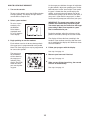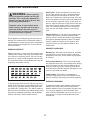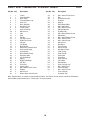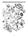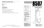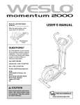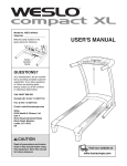
1
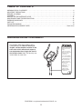
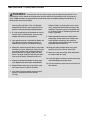
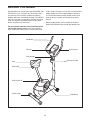
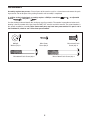
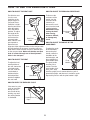
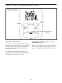
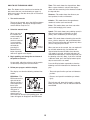
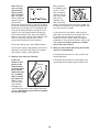
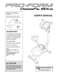
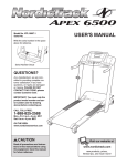
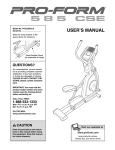
Model No. PFEVEX71908.0
Serial No.
Write the serial number in the
space above for reference.
Serial Number
Decal
QUESTIONS?
As a manufacturer, we are committed to providing complete customer
satisfaction. If you have questions,
or if there are missing parts, please
contact us:
Call: 08457 089 009
Outside UK: 0 (44) 113 3877133
Fax: 0 (44) 113 3877125
E-mail: [email protected]
Write:
ICON Health & Fitness, Ltd.
Unit 4
Revie Road Industrial Estate
Revie Road, Beeston
Leeds, LS11 8JG
UK
CAUTION
Read all precautions and instructions in this manual before using
this equipment. Keep this manual
for future reference.
USER'S MANUAL
TABLE OF CONTENTS
WARNING DECAL PLACEMENT . . . . . . . . . . . . . . . . . . . . . . . . . . . . . . . . . . . . . . . . . . . . . . . . . . . . . . . . . . . . . .2
IMPORTANT PRECAUTIONS . . . . . . . . . . . . . . . . . . . . . . . . . . . . . . . . . . . . . . . . . . . . . . . . . . . . . . . . . . . . . . . .3
BEFORE YOU BEGIN . . . . . . . . . . . . . . . . . . . . . . . . . . . . . . . . . . . . . . . . . . . . . . . . . . . . . . . . . . . . . . . . . . . . . .4
ASSEMBLY . . . . . . . . . . . . . . . . . . . . . . . . . . . . . . . . . . . . . . . . . . . . . . . . . . . . . . . . . . . . . . . . . . . . . . . . . . . . . . .5
HOW TO USE THE EXERCISE CYCLE . . . . . . . . . . . . . . . . . . . . . . . . . . . . . . . . . . . . . . . . . . . . . . . . . . . . . . . .11
MAINTENANCE AND TROUBLESHOOTING . . . . . . . . . . . . . . . . . . . . . . . . . . . . . . . . . . . . . . . . . . . . . . . . . . .16
EXERCISE GUIDELINES . . . . . . . . . . . . . . . . . . . . . . . . . . . . . . . . . . . . . . . . . . . . . . . . . . . . . . . . . . . . . . . . . . .17
PART LIST . . . . . . . . . . . . . . . . . . . . . . . . . . . . . . . . . . . . . . . . . . . . . . . . . . . . . . . . . . . . . . . . . . . . . . . . . . . . . .18
EXPLODED DRAWING . . . . . . . . . . . . . . . . . . . . . . . . . . . . . . . . . . . . . . . . . . . . . . . . . . . . . . . . . . . . . . . . . . . .19
ORDERING REPLACEMENT PARTS . . . . . . . . . . . . . . . . . . . . . . . . . . . . . . . . . . . . . . . . . . . . . . . . . .Back Cover
WARNING DECAL PLACEMENT
This drawing shows the location(s) of the
warning decal(s). If a decal is missing or
illegible, call the telephone number on the
front cover of this manual and request a
free replacement decal. Apply the decal in
the location shown. Note: The decal(s) may
not be shown at actual size.
Misuse of this machine
may result in serious
injury .
Read user’s manual
prior to use and foll ow
all warnings and
inst ruc tions.
Do not allow children
on or around machin e.
User weight must not
exceed 250 pound s.
This product should
always be used on a
level surface.
This produc t is not
intended for
therapeutic use.
Replace label if
damaged, illegible ,
or removed.
PROFORM is a registered trademark of ICON IP, Inc.
2
IMPORTANT PRECAUTIONS
WARNING:
To reduce the risk of serious injury, read all important precautions and
instructions in this manual and all warnings on your exercise cycle before using your exercise
cycle. ICON assumes no responsibility for personal injury or property damage sustained by or
through the use of this product.
8. The pulse sensor is not a medical device.
Various factors, including the user's movement, may affect the accuracy of heart rate
readings. The pulse sensor is intended only
as an exercise aid in determining heart rate
trends in general.
1. Before beginning any exercise program,
consult your physician. This is especially
important for persons over the age of 35 or
persons with pre-existing health problems.
2. It is the responsibility of the owner to ensure
that all users of the exercise cycle are adequately informed of all precautions.
9. Wear appropriate exercise clothes while
exercising; do not wear loose clothes that
could become caught on your exercise
cycle. Always wear athletic shoes for foot
protection while exercising.
3. Your exercise cycle is intended for home use
only. Do not use your exercise cycle in a
commercial, rental, or institutional setting.
10. Keep your back straight while using your
exercise cycle; do not arch your back.
4. Keep your exercise cycle indoors, away from
moisture and dust. Place your exercise cycle
on a level surface, with a mat beneath it to
protect the floor or carpet. Make sure that
there is enough clearance around your exercise cycle to mount, dismount, and use it.
11. When you stop exercising, allow the pedals
to slowly come to a stop.
12. If you feel pain or dizziness while exercising,
stop immediately and cool down.
5. Inspect and properly tighten all parts regularly. Replace any worn parts immediately.
13. Use your exercise cycle only as described in
this manual.
6. Keep children under age 12 and pets away
from your exercise cycle at all times.
7. Your exercise cycle should not be used by
persons weighing more than 250 lbs.
(113 kg).
3
BEFORE YOU BEGIN
Congratulations for selecting the new PROFORM® 180
ZLX exercise cycle. Cycling is one of the most effective exercises for increasing cardiovascular fitness,
building endurance, and toning the body. The 180 ZLX
exercise cycle offers a selection of features designed
to let you enjoy this healthful exercise in the convenience and privacy of your home.
of this manual. To help us assist you, note the product
model number and serial number before contacting
us. The model number and the location of the serial
number decal are shown on the front cover of this
manual.
Before reading further, please review the drawing
below and familiarize yourself with the labeled parts.
For your benefit, read this manual carefully before
you use the exercise cycle. If you have questions
after reading this manual, please see the front cover
Handlebar
Pulse Sensor
Console
Seat
Pivot Handle
Resistance Knob
Seat Knob
Seat Post Knob
Leveling Cap
Pedal/Strap
4
ASSEMBLY
Assembly requires two persons. Place all parts of the exercise cycle in a cleared area and remove the packing materials. Do not dispose of the packing materials until assembly is completed.
In addition to the included tools, assembly requires a Phillips screwdriver
wrench
, and pliers
.
, an adjustable
Use the drawings below to identify the small parts used in assembly. The number in parentheses below each
drawing is the key number of the part, from the PART LIST near the end of this manual. The second number is
the quantity needed for assembly. Note: Some small parts may have been preassembled. If a part is not in
the hardware kit, check to see if it has been preassembled.
M8 Split
Washer (42)–3
M4 x 15mm
Screw (48)–5
M8 x 60mm Patch Screw (30)–4
M8 x 16mm Patch
Screw (34)–3
M10 x 70mm Patch Screw (33)–2
5
1.
1
To make assembly easier, read the
information on page 5 before you begin
assembling the exercise cycle.
Insert the Rear Stabilizer (6) into the Frame (1).
Attach the Rear Stabilizer with four M8 x 60mm
Patch Screws (30).
1
6
30
2. Orient the Front Stabilizer (2) so that the large
holes face the Frame (1). Attach the Front
Stabilizer to the Frame with two M10 x 70mm
Patch Screws (33).
2
33
2
6
Large
Holes
1
3. While another person holds the Upright (13)
near the Frame (1), connect the Extension Wire
(23) to the Reed Switch Wire (39). Next, connect the Resistance Cable (19) to the Lower
Cable (29) in the following way:
3
• See drawing A. Pull upward on the metal
bracket on the Lower Cable (29), and insert
the tip of the Resistance Cable (19) into the
wire clip inside the metal bracket as shown.
• See drawing B. Firmly pull the Resistance
Cable (19) upward and slide it into the top of
the metal bracket as shown.
13
• See drawing C. Using pliers, squeeze the
prongs on the upper end of the metal bracket
together.
Do not pinch the
wires and cables
23
19
Push the Wires (23, 39) and the Cables (19, 29)
downward into the Frame (1).
34
Tip: Do not pinch the wires and cables. Insert
the Upright (13) into the Frame (1). Attach the
Upright with three M8 x 16mm Patch Screws
(34) and three M8 Split Washers (42).
42
1
42
34
B
A
19
7
39
29
Metal
Bracket
29
C
19
29
Metal
Bracket
4. While another person holds the Handlebar (50)
near the Upright (13), insert the Pulse Wires
(59) into the Upright and pull them upward out
of the top of the Upright.
4
Tip: Do not pinch the wires. Attach the
Handlebar (50) to the Upright (13) with the Pivot
Clamp (54), the Rear Cover (3), and the Pivot
Handle (55).
13
59
Note: The Pivot Handle (55) functions like a
ratchet. Turn the Pivot Handle clockwise, pull it
away from the Upright (13), turn it counterclockwise, push it toward the Upright, and then turn it
clockwise again. Repeat this process until the
Pivot Handle is tight.
50
54
3
48
Attach the Rear Cover (3) to the Upright (13)
with an M4 x 15mm Screw (48).
55
Do not pinch
the wires
5. The Console (16) requires four AA batteries (not
included); alkaline batteries are recommended.
IMPORTANT: If the Console has been
exposed to cold temperatures, allow it to
warm to room temperature before inserting
batteries. Otherwise, you may damage the
console displays or other electronic components. Remove the screw, remove the battery
cover, and insert the batteries into the battery
compartment. Then, reattach the battery cover.
Make sure to orient the batteries as shown
by the diagram inside the battery compartment.
5
Screw
16
8
Battery
Cover
Batteries
6. While another person holds the Console (16)
near the Upright (13), connect the console wire
to the Extension Wire (23). Next, connect the
console pulse wires to the Pulse Wires (59).
Then, connect the console ground wire to the
ground wire on the Upright (13).
6
16
Pulse Wires
Ground Wires
Insert the excess wire downward into the
Upright (13).
59
13
Tip: Avoid pinching the wires. Attach the
Console (16) to the Upright (13) with four M4 x
15mm Screws (48).
23
Console Wire
48
7. Loosen and remove the Seat Knob (56) from
the Seat Carriage (58), which is located on the
underside of the Seat (12).
7
12
See the inset drawing. Look underneath the
Seat (12) and locate the Seat Carriage (58).
Next, locate the Seat Block (57) inside the Seat
Carriage.
Set the Seat Carriage (58) in the bracket on the
Seat Post (5). Next, insert the Seat Knob (56)
upward through the bracket on the Seat Post
into the hole in the Seat Block (57). Then, tighten the Seat Knob.
5
12
58
9
58
57
57
56
8. Loosen and remove the Seat Post Knob (9)
from the Frame (1).
Insert the Seat Post (5) into the Frame (1).
Adjust the Seat Post to the desired height and
insert the Seat Post Knob (9) through the indicated hole in the Frame into one of the
adjustment holes in the Seat Post.
8
Tighten the Seat Post Knob (9). Make sure that
the Seat Post Knob is firmly engaged in one
of the adjustment holes in the Seat Post (5).
Adjustment
Holes
5
1
Hole
9
9. Identify the Left Pedal (24), which is marked
with an “L.” Using an adjustable wrench, firmly
tighten the Left Pedal counterclockwise into the
left arm of the Crank (21).
9
Tighten the Right Pedal (not shown) clockwise
into the right arm of the Crank (not shown).
IMPORTANT: Tighten both pedals as firmly
as possible. After using the exercise cycle
for one week, retighten the pedals. For best
performance, keep the pedals tightened.
Strap
21
24
Tab
Adjust the strap on the Left Pedal (24) to the
desired position, and press the end of the strap
onto the tab on the side of the Left Pedal.
Adjust the strap on the Right Pedal (not
shown) in the same way.
10. Make sure that all parts are properly tightened before you use the exercise cycle. Note: After assembly
is completed, some extra parts may be left over. Place a mat beneath the exercise cycle to protect the floor.
10
HOW TO USE THE EXERCISE CYCLE
HOW TO ADJUST THE SEAT POST
HOW TO ADJUST THE PEDALING RESISTANCE
For effective exercise, the seat
should be at the
proper height. As
you pedal, there
Seat
should be a slight
bend in your knees
when the pedals
are in the lowest
Seat Post
position. To adjust
the height of the
seat, first loosen
Hole
and remove the
Seat Post
seat post knob.
Knob
Next, slide the seat
post upward or
downward and
align one of the adjustment holes in the seat post with
the indicated hole in the frame. Insert the seat post
knob into the frame and the seat post, and then tighten the seat post knob. Make sure that the seat post
knob is inserted through one of the adjustment
holes in the seat post.
To increase the
resistance of the
pedals, turn the
resistance knob
clockwise; to
decrease the resistance, turn the knob
counterclockwise.
IMPORTANT: Stop
turning the knob
when turning
becomes difficult,
or damage may
result.
HOW TO ADJUST THE ANGLE OF THE
HANDLEBAR
To adjust the angle
of the handlebar,
loosen the pivot
handle, rotate the
handlebar to the
desired angle, and
then retighten the
Pivot
pivot handle. Note:
Handle
The pivot handle
functions like a
ratchet. Turn the
pivot handle clockwise, pull it away
from the upright, turn it counterclockwise, push it
toward the upright, and then turn it clockwise again.
Repeat this process until the pivot handle is tight.
HOW TO ADJUST THE SEAT
To adjust the horizontal position of
the seat, loosen the
seat knob under
the seat, slide the
seat forward or
backward to the
desired position,
and then retighten
the seat knob.
Seat
Seat Knob
HOW TO LEVEL THE EXERCISE CYCLE
If the exercise cycle
rocks on your floor
during use, turn
one or both of the
leveling caps until
the rocking motion
is eliminated.
Resistance
Knob
Leveling
Caps
11
HOW TO USE THE EXERCISE CYCLE
CONSOLE DIAGRAM
Display
Button
On/Reset
Button
Workout Select
Button
FEATURES OF THE CONSOLE
To use the manual mode, see page 13. To use a
pace workout, see page 15.
The console offers a selection of features designed to
make your workouts more effective. As you pedal, the
console will provide continuous exercise feedback.
You can even measure your heart rate using the
handgrip pulse sensor.
Before using the console, make sure that batteries are
installed (see assembly step 5 on page 8). If there is a
sheet of clear plastic on the display, remove the plastic.
The console also offers two pace workouts that
prompt you to vary your pedaling pace while guiding
you through an effective exercise session.
12
HOW TO USE THE MANUAL MODE
Time—This mode shows the elapsed time. Note:
When a pace workout is selected, the display
shows the time remaining in the workout instead of
the elapsed time.
Note: The buttons on the console are located on the
dots next to the text (see the drawing on page 12).
Make sure to press the dots when you are instructed
to press a button.
Distance—This mode shows the distance you
have pedaled, in miles or kilometers.
1. Turn on the console.
Calories—This mode shows the approximate
number of calories you have burned.
To turn on the console, press the On/Reset button
or begin pedaling. The display will light and the
console will be ready for use.
Pulse—This mode shows your heart rate when
you use the handgrip pulse sensor.
2. Select the manual mode.
Speed—This mode shows your pedaling speed, in
miles per hour (mph) or kilometers per hour
(km/h), and in revolutions per minute (rpm).
When you turn on
Indicators
the console, the
manual mode will
be selected. If
you have selected
a pace workout,
reselect the manual mode by
pressing the
Indicators
Workout Select
button repeatedly
until zeros appear in the display.
Scan—This mode shows alternating time and distance, calories and pulse, and speed information.
Note: The pulse information will appear only when
you are using the pulse sensor.
When you turn on the console, the scan mode will
be selected automatically. One indicator will
appear below the word SCAN to show that the
scan mode is selected, and other indicators will
show which information is currently displayed (see
the drawing at the left). Note: If you have selected
a different mode, press the Display button repeatedly to reselect the scan mode.
3. Begin pedaling and change the resistance of
the pedals as desired.
As you pedal, adjust the resistance of the pedals
as desired by turning the resistance knob.
Press the Display button repeatedly to view the
following exercise information for continuous display:
4. Follow your progress with the display.
The display can show the following workout information:
• Time and speed in miles per hour or kilometers
per hour
RPM Meter—The
RPM meter on the
right side of the
display provides a
visual representation of your
approximate pedaling pace in
RPM Meter
revolutions per
minute (rpm). As
you increase or decrease your pedaling pace, indicators will appear or disappear in the RPM meter.
• Distance and speed in revolutions per minute
(rpm)
The indicators will show which mode is selected.
Make sure that there is not an indicator below the
word SCAN.
13
Note: The console can show
speed and distance in either
miles or kilometers. The letters
MPH or Km/H will
appear in the display to show
which unit of measurement is selected. To change
the unit of measurement, hold down the On/Reset
button for a few seconds. An “E” for English miles
or an “M” for metric kilometers will appear in the
display. Press the Display button to change the
unit of measurement. Then, press the On/Reset
button to save your selection. Note: When the batteries are replaced, it may be necessary to
reselect the desired unit of measurement.
When you hold
the handgrip pulse
sensor, a small
heart symbol will
appear in the display. Then, when
your pulse is
detected, your
heart rate will be
shown in the display next to the heart symbol. For
the most accurate heart rate reading, hold the contacts for at least 15 seconds.
If your heart rate is not shown, make sure that
your hands are positioned as described. Be careful not to move your hands excessively or to
squeeze the metal contacts tightly. For optimal
performance, clean the metal contacts using a soft
cloth; never use alcohol, abrasives, or chemicals to clean the contacts.
To reset the display, press the On/Reset button.
6. When you are finished exercising, the console
will turn off automatically.
To pause the console, stop pedaling. If the time is
displayed, it will flash in the display. To continue
your workout, simply resume pedaling.
If the pedals do not move for a few seconds, the
console will pause.
5. Measure your heart rate if desired.
If there are
sheets of clear
plastic on the
Contacts
metal contacts
on the handgrip
pulse sensor,
remove the plastic. In addition,
make sure that
your hands are
clean. To measure your heart
rate, hold the
handgrip pulse
sensor with your palms resting against the metal
contacts. Avoid moving your hands or gripping
the contacts tightly.
If the pedals do not move for a few minutes, the
console will turn off and the display will be reset.
14
HOW TO USE A PACE WORKOUT
As the target pace indicator changes in height during the workout, adjust your pedaling pace so that
both indicators are the same height. If your pedaling pace is slower than the current target pace
setting, an upward arrow will appear next to the
RPM meter to prompt you to increase your pace; if
your pace is faster than the target pace, a downward arrow will prompt you to decrease your pace.
1. Turn on the console.
To turn on the console, press the On/Reset button
or begin pedaling. The display will light and the
console will be ready for use.
2. Select a pace workout.
IMPORTANT: The target pace settings for the
workout are intended only to provide a goal.
Your actual pace may be slower than the target
pace settings. Make sure to pedal at a pace
that is comfortable for you.
To select a pace
workout, press
the Workout
Select button
repeatedly until
P1 or P2 appears
in the display.
During the workout, adjust the resistance of the
pedals as desired by turning the resistance knob.
The display will show the time remaining in the
workout. If you continue exercising after the workout is completed, the display will continue to show
exercise feedback.
3. Begin pedaling to start the workout.
Each workout consists of 30 one-minute periods.
One target pace is programmed for each period.
Note: The same target pace may be programmed
for consecutive periods.
The target pace
for the workout
will be shown by
the target pace
indicator in the
display. The RPM
meter will show
your actual pedaling pace.
4. Follow your progress with the display.
See step 4 on page 13.
Target Pace Indicator
5. Measure your heart rate if desired.
See step 5 on page 14.
6. When you are finished exercising, the console
will turn off automatically.
See step 6 on page 14.
RPM Meter
15
MAINTENANCE AND TROUBLESHOOTING
When the Reed Switch is correctly adjusted, reattach
the shields and the left pedal.
Inspect and tighten all parts of the exercise cycle regularly. Replace any worn parts immediately.
HOW TO ADJUST THE BELT
To clean the exercise cycle, use a damp cloth and a
small amount of mild detergent. IMPORTANT: To
avoid damage to the console, keep liquids away
from the console and keep the console out of
direct sunlight.
If you can feel the pedals slip while you are pedaling,
even when the resistance is at the highest level, the
belt may need to be adjusted. To adjust the belt, the
pedals and the shields must be removed.
CONSOLE TROUBLESHOOTING
Use an adjustable wrench to remove the pedals. To
remove the left pedal, turn the left pedal clockwise; to
remove the right pedal, turn the right pedal counterclockwise.
If the console display becomes dim, the batteries
should be replaced; most console problems are the
result of low batteries. To replace the batteries, see
assembly step 5 on page 8. If the handgrip pulse sensor does not function properly, see step 5 on page 14.
Next, remove all of the screws from both shields; there
are two sizes of screws in the shields—note which
size of screw you remove from each hole. Then,
carefully remove the shields.
HOW TO ADJUST THE REED SWITCH
If the console does not display correct feedback, the
reed switch should be adjusted. To adjust the reed
switch, the left pedal and the left shield must be
removed.
Using an adjustable wrench, turn the left pedal clockwise and remove it. Next, remove all of the screws
from both shields; there are two sizes of screws in
the shields—note which size of screw you remove
from each hole. Then, carefully remove the left shield.
43
35
27
39
47
38
32
Next, loosen the 3/8" Nut (27) and the Flywheel Nut
(43), which are located on each side of the Flywheel
(37). Then, tighten the M6 Locknuts (32), one on each
side of the Flywheel, until the Belt (35) is properly
tightened.
21
Next, turn the resistance knob to the lowest setting.
With the left shield removed, locate the Reed Switch
(39). Turn the Crank (21) until a Magnet (38) is
aligned with the Reed Switch. Loosen, but do not
remove, the M5 x 15mm Screw (47). Slide the Reed
Switch slightly closer to or away from the Magnet, and
then retighten the Screw. Turn the Crank for a
moment. Repeat until the console displays correct
feedback.
37
Finally, tighten the 3/8" Nut (27) and the Flywheel Nut
(43) and reattach the shields and the pedals.
16
EXERCISE GUIDELINES
WARNING: Before beginning
Burning Fat—To burn fat effectively, you must exercise at a low intensity level for a sustained period of
time. During the first few minutes of exercise, your
body uses carbohydrate calories for energy. Only after
the first few minutes of exercise does your body begin
to use stored fat calories for energy. If your goal is to
burn fat, adjust the intensity of your exercise until your
heart rate is near the lowest number in your training
zone. For maximum fat burning, exercise with your
heart rate near the middle number in your training
zone.
this or any exercise workout, consult your
physician. This is especially important for
persons over the age of 35 or persons with
pre-existing health problems.
The pulse sensor is not a medical device.
Various factors may affect the accuracy of
heart rate readings. The pulse sensor is
intended only as an exercise aid in determining heart rate trends in general.
Aerobic Exercise—If your goal is to strengthen your
cardiovascular system, you must perform aerobic
exercise, which is activity that requires large amounts
of oxygen for prolonged periods of time. For aerobic
exercise, adjust the intensity of your exercise until
your heart rate is near the highest number in your
training zone.
These guidelines will help you to plan your exercise
workout. For detailed exercise information, obtain a
reputable book or consult your physician. Remember,
proper nutrition and adequate rest are essential for
successful results.
WORKOUT GUIDELINES
EXERCISE INTENSITY
Warming Up—Start with 5 to 10 minutes of stretching
and light exercise. A warm-up increases your body
temperature, heart rate, and circulation in preparation
for exercise.
Whether your goal is to burn fat or to strengthen your
cardiovascular system, exercising at the proper intensity is the key to achieving results. You can use your
heart rate as a guide to find the proper intensity level.
The chart below shows recommended heart rates for
fat burning and aerobic exercise.
Training Zone Exercise—Exercise for 20 to 30 minutes with your heart rate in your training zone. (During
the first few weeks of your exercise workout, do not
keep your heart rate in your training zone for longer
than 20 minutes.) Breathe regularly and deeply as you
exercise–never hold your breath.
Cooling Down—Finish with 5 to 10 minutes of
stretching. Stretching increases the flexibility of your
muscles and helps to prevent post-exercise problems.
EXERCISE FREQUENCY
To find the proper intensity level, find your age at the
bottom of the chart (ages are rounded off to the nearest ten years). The three numbers listed above your
age define your “training zone.” The lowest number is
the heart rate for fat burning, the middle number is the
heart rate for maximum fat burning, and the highest
number is the heart rate for aerobic exercise.
To maintain or improve your condition, complete three
workouts each week, with at least one day of rest
between workouts. After a few months of regular exercise, you may complete up to five workouts each
week, if desired. Remember, the key to success is to
make exercise a regular and enjoyable part of your
everyday life.
17
PART LIST—Model No. PFEVEX71908.0
Key No. Qty.
1
2
3
4
5
6
7
8
9
10
11
12
13
14
15
16
17
18
19
20
21
22
23
24
25
26
27
28
29
30
31
32
33
1
1
1
2
1
1
2
2
1
4
1
1
1
1
1
1
1
1
1
1
1
1
1
1
1
1
1
2
1
4
2
2
2
Description
Key No. Qty.
Frame
Front Stabilizer
Rear Cover
Front Stabilizer Cap
Seat Post
Rear Stabilizer
Handlebar Cap
Leveling Cap
Seat Post Knob
M8 Locknut
Idler
Seat
Upright
Left Front Cover
Right Front Cover
Console
Left Shield
Right Shield
Resistance Control/Cable
Seat Post Bushing
Crank/Pulley
Reed Switch Clamp
Extension Wire
Left Pedal/Strap
Spring
Right Pedal/Strap
3/8" Nut
U-bracket
Lower Cable
M8 x 60mm Patch Screw
Eyebolt
M6 Locknut
M10 x 70mm Patch Screw
34
35
36
37
38
39
40
41
42
43
44
45
46
47
48
49
50
51
52
53
54
55
56
57
58
59
60
61
62
63
64
*
*
3
1
1
1
2
1
1
7
7
3
1
1
8
1
9
1
1
2
2
2
1
1
1
1
1
2
1
2
1
1
1
–
–
Description
M8 x 16mm Patch Screw
Belt
Crank Bearing Set
Flywheel
Magnet
Reed Switch/Wire
M8 x 20mm Bolt
M4 x 25mm Screw
M8 Split Washer
Flywheel Nut
M5 x 55mm Button Screw
M8 Washer
M4 x 15mm Button Screw
M5 x 15mm Screw
M4 x 15mm Screw
M8 Locknut
Handlebar
Pulse Sensor
Sensor Screw
Handlebar Foam
Pivot Clamp
Pivot Handle
Seat Knob
Seat Block
Seat Carriage
Pulse Wire
Ground Wire
Seat Carriage Cap
M4 x 5mm Screw
Frame Bushing
M4 x 12mm Screw
Userʼs Manual
Assembly Tool
R0808A
Note: Specifications are subject to change without notice. See the back cover of this manual for information
about ordering replacement parts. *These parts are not illustrated.
18
EXPLODED DRAWING—Model No. PFEVEX71908.0
46
16
60
48
53
51
7
51
52
4
46
41
48
50
15 48
54
14
44
59
19
13
52
34
2
33
62
34
42
4
42
47
39
46
48
3
55
5
63
23
1
48
56
64
49
46
17
27
46
12
58
61
42
10
42
10
20
9
28
61
38
19
21
38
10
29
11 40
25
43
43
8
30
8
6
31
28
37
43
32
41
26
57
42
45
31
35
41
18
36
22
24
41
R0808A
32
ORDERING REPLACEMENT PARTS
To order replacement parts, please see the front cover of this manual. To help us assist you, be prepared to
provide the following information when contacting us:
• the model number and serial number of the product (see the front cover of this manual)
• the name of the product (see the front cover of this manual)
• the key number and description of the replacement part(s) (see the PART LIST and the EXPLODED
DRAWING near the end of this manual)
Part No. 269393 R0808A
Printed in China © 2008 ICON IP, Inc.