1
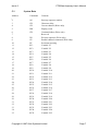
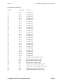
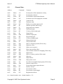
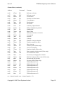
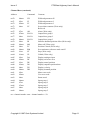
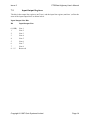
PTS/Data Highway Interface Software
User’s Manual
Issue 2
February 1997
MAN527
Issue 2
PTS/Data Highway User’s Manual
Contents
1.
Introduction
1
2.
Program Functions
2
3.
Programming
3.1 General
3.2 Register Size
3.3 Files and Messages
3.4 Protocol
3
3
3
3
3
4.
Configuring the PTS
4.1 Software License Key
4.2 Serial Port
4.3 Data Highway Protocol
4
4
5
5
5.
Address Map
5.1 System Data
5.2 Channel Data
6
7
9
6.
Error Codes
12
7.
Register Bit Mapping
7.1 Status Word Register
7.2 Input/Output Registers
13
13
14
Copyright © 1997 Quin Systems Limited
Page 2
Issue 2
1.
PTS/Data Highway User’s Manual
Introduction
This manual relates to the following versions of software in the Mini-PTS and PTS Mark 2
units:
Data Highway Interface Version 1.1
PTS Host software
Version 1.8.2 or later
This document describes the PTS/Data Highway Interface. This provides considerable
flexibility in operating the machine - allowing changes to the program to be made quickly and
easily by the user. It also ensures that improvements to the standard PTS product can be readily
incorporated into any machine. The PTS units use the Quin Motor Control language which is
described fully in the relevant PTS Reference Manual.
Control of the machine is accomplished in the following way:
•
The control system communicates with the PTS unit as if it were a PLC. This allows
the control system to display information about the running of the machine which it gets
from the PTS. In a similar manner the operator can control the machine from the control
system.
•
The PTS unit controls the running of the motors according to setup data received from
the control system. The interface to the control system is via the auxiliary serial port,
thus leaving the main serial port available for initial machine setup and diagnostics.
•
It is envisaged that most of the digital I/O such as guard switches will be taken care of
using a PLC.
Copyright © 1997 Quin Systems Limited
Page 1
Issue 2
2.
PTS/Data Highway User’s Manual
Program Functions
The Data Highway interface to the PTS allows the control system to control and monitor the
operation of the machine by communicating with the PTS directly over a RS232 or RS422
serial link.
The functions which the PTS/Data Highway interface accomplishes are as follows:
•
Monitoring machine status. The control system can interrogate the PTS to determine
whether any motor errors have occurred, or to find the current channel status for
example. It is also possible to examine the current setting of parameters such as the
velocity, position, etc.
•
Machine control. The control system can control the PTS by initiating preprogrammed
sequences. It is also able to execute most of the normal PTS commands such as setting
the velocity, executing a move and so on.
Machine control and monitoring are achieved from the control system by reading from/writing
to registers within the PTS in the same way as a PLC would be controlled and monitored. The
communication with the PTS is done using the Data Highway DF1 protocol. Registers are 16bit locations for input and/or output. The PTS interface maps the registers onto standard PTS
commands in a predetermined manner thus allowing the operator to accomplish most of the
things that are possible using the standard PTS command language.
Copyright © 1997 Quin Systems Limited
Page 2
Issue 2
PTS/Data Highway User’s Manual
3.
Programming
3.1
General
The Data Highway interface to the PTS is designed to make the PTS look like a PLC as much
as possible. To achieve this, the PTS appears as a number of registers or elements which can
be read or written as appropriate by the control system using the Data Highway interface. Each
PTS channel has its own set of registers to allow random access to most of the data in the PTS.
In addition there is a set of registers for system-wide data which is not specific to a particular
channel. It is possible to address the channel data in two ways. Using the standard method,
consecutive registers access different data items from the same channel. Using the alternative
method, consecutive registers access the same data item on different channels.
3.2
Register Size
It should be noted that the Data Highway DF1 protocol can only handle 16 bit numbers and
therefore the units on the PTS must be set to ensure all data falls within this range. This is
accomplished with the SU command.
3.3
Files and Messages
The PTS appears to a remote system as a single file which contains all the registers as elements
in the file. The PTS ignores the file number contained in incoming messages and will therefore
accept messages addressed to any given file.
The PTS recognizes the following PLC-5 messages.
Word Range Write (Block Write) (function code 00)
Word Range Read (Block Read) (function code 01)
Typed Write (function code 67)
Typed Read (function code 68)
The PTS accepts logical Binary addresses or logical ASCII addresses of the form:
$Nff:eee
where ff is the file number which is currently ignored
and eee is the element or register number as descibed in the following pages.
3.4
Protocol
The PTS is intended to be connected to the Data Highway network using the KF2 interface
module or equivalent. The PTS recogniozes the Data Highway Full Duplex DF1 protocol and
can be configured to use either RS232 or RS422 serial port characteristics. The serial line
parameters are as follows.
9600 Baud
8 bit characters
1 stop bit
No parity
Copyright © 1997 Quin Systems Limited
Page 3
Issue 2
PTS/Data Highway User’s Manual
4.
Configuring the PTS
4.1
Software License Key
The software for the Data Highway interface will not operate unless a software key has been
entered to enable this option. The software key is different for each PTS and can be obtained
from your sales office given the system serial number which can be found by using the SK
command as shown below. Note that all options which use the second serial port are mutually
exclusive. These options are the standard Operator’s panel, Mini Operator’s panel, the Modbus
interface and the Data Highway interface.
To enable the software the following command should be entered on Port A (the main
programming port) in privileged mode. You enter the text in bold while the PTS displays
something similar to the rest.
1> SK
Serial number: 006545
Feature
Version
Key
New feature ? datahw
Version ? 1.1
Key ? abcd
OK
Note that the feature name (datahw) must be entered in lower case exactly as shown above.
Note also that it is necessary to turn the power off and back on again to run the Data Highway
software.
If the software needs to be disabled, first make a note of the software key in case it is needed
in the future. Then proceeed as above but simply press the Return key in response to the
"Version ? " prompt as follows.
1> SK
Serial number: 006545
Feature
Version
Key
datahw
1.1
ABCD
New feature ? datahw
Version ?
Feature datahw removed
Copyright © 1997 Quin Systems Limited
Page 4
Issue 2
4.2
PTS/Data Highway User’s Manual
Serial Port
The Data Highway interface uses Port B of the PTS which can be configured to be either RS232
or RS422 levels using a PTS command on the Mini-PTS 2+1, Mini-PTS 3 and PTS Mark 2. To
change the serial port configuration the following command should be entered on Port A (the
main programming port) in privileged mode. You enter the text in bold while the PTS displays
something similar to the rest.The example demonstrates changing Port B from RS232 to
RS422.
1> CF
Port Configuration
A
RS232
S/W
B
RS232
N/A
D
Stn 1
BCC
Port ? B
Type ? RS422
OK
4.3
Data Highway Protocol
Certain details of the Data Highway protocol implementation can be configured using the CF
command to change the configuration of Port D. These are the station number of the PTS on
the Data Highway network and the type of checksum used on messages to and from the PTS.
It is important to set these parameters correctly to ensure that the PTS recognizes commands
sent to it and reponds correctly to those commands. The following example demonstrates
changing the station number to 1 and the checksum type to CRC (the default values).
1> CF
Port Configuration
A
RS232
S/W
B
RS485
N/A
D
Stn 5
BCC
Port ? D
Station number ? 1
Checksum type (BCC or CRC) ? CRC
OK
Copyright © 1997 Quin Systems Limited
Page 5
Issue 2
5.
PTS/Data Highway User’s Manual
Address Map
The data is organized in read/write registers as shown on the following pages. Each piece of
data is accessible at two addresses. The first addressing mode allows different data items on the
same channel to be accessed at consecutive addresses. The channel number is shown by the
hundreds digit and is represented by “nn” in the tables. Addresses below 100 are used for
system-wide data items which are not specific to a particular channel. The second addressing
mode is used for addresses above 5000, and allows the same data item on all channels to be
accessed at consecutive addresses.
For example the control word (CW) for channel 1 can be accessed as register 106, the control
word for channel 3 can be accessed at address 306 and so on. If multiple registers are written
starting at register 106, then this will alter the control word (CW), debounce time (DB), zero
marker input (DZ) etc. for channel 1. The control word for channel 1 can also be accessed as
register 5251, for channel 2 at 5252, for channel 3 at 5253 and so on. The debounce time for
channel 1 can be accessed at 5301, for channel 2 at 5302 and so on. This addressing mode is
useful because it allows a given data item for all channels to be accessed using a single
communications block and so uses the network more efficiently. The register number is given
in the tables first for addressing mode 1 (data item consecutive) and secondly for addressing
mode 2 (channel consecutive).
It should be noted that certain commands are marked in the tables as write only and will
therefore not return a meaningful value when read.
Copyright © 1997 Quin Systems Limited
Page 6
Issue 2
5.1
Address
Address
Mode 1
2
3
4
5
6
7
8
9
10
11
12
13
14
15
16
17
18
19
20
21
22
23
24
25
26
27
28
29
30
31
32
33
34
35
PTS/Data Highway User’s Manual
System Data
Mode 2
Command
Command
Contents
Contents
AS
CD
CH
DW
GX
Start-up sequence number
Character delay
Current channel (Write only)
Display word
Command abort (Write only)
Reserved
Execute sequence (Write only)
Parallel channel command (Write only)
Set status reporting
Variable V1
Variable V2
Variable V3
Variable V4
Variable V5
Variable V6
Variable V7
Variable V8
Variable V9
Variable V10
Variable V11
Variable V12
Variable V13
Variable V14
Variable V15
Variable V16
Variable V17
Variable V18
Variable V19
Variable V20
Variable V21
Variable V22
Variable V23
Variable V24
Variable V25
XS
CP
SY
$V1
$V2
$V3
$V4
$V5
$V6
$V7
$V8
$V9
$V10
$V11
$V12
$V13
$V14
$V15
$V16
$V17
$V18
$V19
$V20
$V21
$V22
$V23
$V24
$V25
Copyright © 1997 Quin Systems Limited
Page 7
Issue 2
PTS/Data Highway User’s Manual
System Data (continued)
Address
Command
Contents
36
37
38
39
40
41
42
43
44
45
46
47
48
49
50
51
52
53
54
55
56
57
58
59
60
81
82
83
84
85
86
87
88
$V26
$V27
$V28
$V29
$V30
$V31
$V32
$V33
$V34
$V35
$V36
$V37
$V38
$V39
$V40
$V41
$V42
$V43
$V44
$V45
$V46
$V47
$V48
$V49
$V50
CM
RD
RS
ER
GA
GF
GS
GX
Variable V26
Variable V27
Variable V28
Variable V29
Variable V30
Variable V31
Variable V32
Variable V33
Variable V34
Variable V35
Variable V36
Variable V37
Variable V38
Variable V39
Variable V40
Variable V41
Variable V42
Variable V43
Variable V44
Variable V45
Variable V46
Variable V47
Variable V48
Variable V49
Variable V50
Compile sequences (Write only)
Read parameters (Write only)
Reset parameters (Write only)
End repeat loop (Write only)
Global abort command (Write only)
Global motor-off command (Write only)
Global stop command (Write only)
Global command abort (Write only)
Copyright © 1997 Quin Systems Limited
Page 8
Issue 2
5.2
PTS/Data Highway User’s Manual
Channel Data
Address
nn02
nn03
nn04
nn05
nn06
nn07
nn08
nn09
nn10
nn11
nn12
nn13
nn14
nn15
nn16
nn17
nn18
nn19
nn20
nn21
nn22
nn23
nn24
nn25
nn26
nn27
nn28
nn29
nn30
nn31
nn32
nn33
nn34
nn35
50mm
51nn
51mm
52nn
52mm
53nn
53mm
54nn
54mm
55nn
55mm
56nn
56mm
57nn
57mm
58nn
58mm
59nn
59mm
60nn
60mm
61nn
61mm
62nn
62mm
63nn
63mm
64nn
64mm
65nn
65mm
66nn
66mm
67nn
Command
Contents
AV
BA
BL
BT
CW
DB
DZ
IN
IT
KD
KF
KI
KM
KP
KV
LH
LL
MA
MB
ME
MF
ML
MP
MR
MS
MT
MW
OC
OM
PA
PV
RF
RL
RT
Set map base/offset adjustment velocity
Set map base advance
Set backlash compensation distance
Set master speed averaging time constant
Control word
Debounce time
Define zero marker input on/off
Initialise position (Write only)
Integration time constant
Differential gain
Velocity feed-forward gain
Integral gain
Monitor output gain
Proportional gain
Velocity feedback gain
High position limit
Low position limit
Move to absolute position (Write only)
Map base offset
Motor error sequence
Slave map position offset
Link to master channel for mapping (Write only)
Map bound
Move to relative position (Write only)
Map step
Map timeout
Map options word
Set value on expanded output group (Write only)
Monitor output offset
Set position trigger output advance
Profile velocity
Set reference offset
Set reference repeat length
Registration timeout
nn = channel number. mm = channel number + 50.
Copyright © 1997 Quin Systems Limited
Page 9
Issue 2
PTS/Data Highway User’s Manual
Channel Data (continued)
Address
nn36
nn37
nn38
nn39
nn40
nn41
nn42
nn43
nn44
nn45
nn46
nn47
nn48
nn49
nn50
nn51
nn52
nn53
nn54
nn55
nn56
nn57
nn58
nn59
nn60
nn61
nn62
nn63
nn64
nn65
nn66
nn67
nn68
nn69
67mm
68nn
68mm
69nn
69mm
70nn
70mm
71nn
71mm
72nn
72mm
73nn
73mm
74nn
74mm
75nn
75mm
76nn
76mm
77nn
77mm
78nn
78mm
79nn
79mm
80nn
80mm
81nn
81mm
82nn
82mm
83nn
83mm
84nn
Command
Contents
RV
RW
SA
SB
SC
SD
SE
SF
SJ
SL
SM
SR
SS
SU
SV
SW
TM
TO
TP
UE
US
VC
VM
VT
WC
XM
XP
YA
YB
YC
YD
YE
YF
YG
Reference velocity
Reference word
Acceleration
Position overflow bound
Creep distance
Deceleration
Error band
Auxiliary output function
Deferred adjustment position
Settling time
Map scaling
Maximum reference correction
Creep speed
Set units
Velocity
Window on move endpoint
Transfer map (Write only)
Move timeout
Transfer profile (Write only)
User error sequence
Send user signal (Write only)
Enter constant velocity mode (Write only)
Set virtual motor mode
Set velocity averaging time constant
Wait for bound overflow count (Write only)
Execute map (Write only)
Execute profile (Write only)
Wildcard parameter A
Wildcard parameter B
Wildcard parameter C
Wildcard parameter D
Wildcard parameter E
Wildcard parameter F
Wildcard parameter G
nn = channel number. mm = channel number + 50.
Copyright © 1997 Quin Systems Limited
Page 10
Issue 2
PTS/Data Highway User’s Manual
Channel Data (continued)
Address
nn70
nn71
nn72
nn73
nn74
nn75
nn76
nn77
nn78
nn79
nn80
nn81
nn82
nn83
nn84
nn85
nn86
nn87
nn88
nn89
nn90
nn91
nn92
nn93
nn94
nn95
nn96
nn97
nn98
Command
Contents
84mm
85nn
85mm
86nn
YH
YI
YJ
ZC
87nn
87mm
88nn
88mm
89nn
89mm
90nn
90mm
91nn
91mm
92nn
92mm
93nn
93mm
94nn
94mm
95nn
95mm
96nn
96mm
97nn
97mm
98nn
98mm
AB
SO/CO
SO/CO
SO/CO
ID
MO
PC
RM
ST
UL
DA
DF
DP
DS
DV
DD
Wildcard parameter H
Wildcard parameter I
Wildcard parameter J
Set position counters (Write only)
Reserved
Abort (Write only)
Output lines group 1
Output lines group 2
Output lines group 3
Initialise demand position offset (Write only)
Motor off (Write only)
Position Control (Write only)
Set continuous reference mode on/off
Stop (Write only)
Unlink (Write only)
Display analogue input
Display reference error
Display actual position
Display snapshot position data
Display velocity
Display demand position
Motor error code
User error code
Status word
Input group 1
Input group 2
Input group 3
Input group 4
Input group 5
nn = channel number. mm = channel number + 50.
Copyright © 1997 Quin Systems Limited
Page 11
Issue 2
6.
PTS/Data Highway User’s Manual
Error Codes
System error codes can be read from channel registers nn91 and nn92. These registers hold
respectively the last motor error and last user error which occurred on channel nn. The codes
are given in section 5.4 of the relevant PTS Reference Manual.
Copyright © 1997 Quin Systems Limited
Page 12
Issue 2
PTS/Data Highway User’s Manual
7.
Register Bit Mapping
7.1
Status Word Register
The meaning of the value in the Status word register (channel register nn93) are shown below.
Status Value
Value
Meaning when set
1
2
3
4
5
6
7
256
512
1024
2048
4096
8192
16384
32768
Waiting for time (WT)
Waiting for input line (WI)
Waiting for absolute position (WA)
Waiting for relative position (WR)
Waiting for reference signal (WR)
Waiting for bounds wraparound (WB)
Waiting for bounds counter value (WC)
Constant velocity mode (VC)
Moving (MA/MR)
Profiling (XP)
Mapping (XM)
Stopping (ST)
Initialising (IN)
Torque control mode (TQ)
Motor off
Copyright © 1997 Quin Systems Limited
Page 13
Issue 2
7.2
PTS/Data Highway User’s Manual
Input/Output Registers
The bits in the output line registers (nn76 etc.) and the input line register (nn94 etc.) reflect the
state of the input/output lines as shown below.
Input/Output Line Bits
Bit
Input/Output Line
0 (LSB)
1
2
3
4
5
6
7
8 .. 15
Line 1
Line 2
Line 3
Line 4
Line 5
Line 6
Line 7
Line 8
Reserved
Copyright © 1997 Quin Systems Limited
Page 14