1
USB Protocol Suite
User Manual
Software Version 4.75
Document Version 4.75
September 2013
Trademarks and Servicemarks
CATC, Teledyne LeCroy Voyager, Voyager ReadyLink, USB Protocol Suite, USB Advisor, Advisor T3, Mercury T2, USB Chief, USB Inspector, USB Detective, USB Tracer/Trainer, and BusEngine are trademarks of Teledyne LeCroy.
Microsoft and Windows are registered trademarks of Microsoft Corporation.
Intel and Pentium are registered trademarks of Intel Corporation.
All other trademarks and registered trademarks are property of their respective owners.
THE SPECIFICATIONS AND INFORMATION REGARDING THE PRODUCTS IN THIS MANUAL ARE SUBJECT TO CHANGE WITHOUT NOTICE. ALL INFORMATION, EXAMPLES AND RECOMMENDATIONS IN THIS MANUAL ARE BELIEVED TO BE ACCURATE BUT ARE REPRESENTED WITHOUT WARRANTY OF ANY KIND, EXPRESS OR IMPLIED. USERS ARE FULLY RESPONSIBLE FOR THEIR APPLICATION OF ANY PRODUCTS.
THE SOFTWARE LICENSE AND LIMITED WARRANTY FOR THE ACCOMPANYING PRODUCT ARE SET FORTH IN INFORMATION THAT SHIPPED WITH THE PRODUCT AND ARE INCORPORATED HEREIN BY THIS REFERENCE. IF YOU ARE UNABLE TO LOCATE THE SOFTWARE LICENSE OR LIMITED WARRANTY, CONTACT Teledyne LeCroy FOR A COPY.
© 2008 Teledyne LeCroy, Inc; All rights reserved.
This document may be printed and reproduced without additional permission, but all copies should contain this copyright notice.
WEEE Program Teledyne LeCroy 3385 Scott Blvd.
Santa Clara, CA 95054
TEL: 800‐909‐7112 (USA and Canada)
TEL: 408‐653‐1260 (worldwide)
USB Protocol Suite User Manual
2
Contents
Chapter 1: Overview............................................................................................... 17
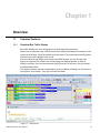
1.1 Common Features ..................................................................................................................17
1.1.1 Graphical Bus Traffic Display ..................................................................................................................... 17
1.1.2 Accurate Time Measurement (Voyager, Advisor T3) ................................................................................ 18
1.1.3 CrossSync Control Panel (Voyager, Advisor T3)...................................................................................... 18
1.1.4 Comprehensive Error Detection and Analysis.......................................................................................... 18
1.1.5 Real-Time Event Triggering and Capture Filtering ................................................................................... 19
1.1.6 BusEngine Technology ............................................................................................................................... 19
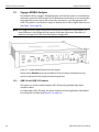
1.2 Voyager M3/M3i Analyzer.......................................................................................................20
1.2.1 USB 2.0 and USB 3.0 Features.................................................................................................................... 20
1.2.2 General Description ..................................................................................................................................... 21
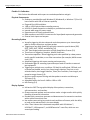
1.2.3 Features ........................................................................................................................................................ 22
General ...........................................................................................................................................................................
Flexible 3.0 Calibration..................................................................................................................................................
Physical Components ...................................................................................................................................................
Recording Options ........................................................................................................................................................
Display Options .............................................................................................................................................................
22
23
23
23
23
1.2.4 Hi-Speed Slow Clock ................................................................................................................................... 24
1.2.5 Traffic Generation ........................................................................................................................................ 24
ReadyLink™ Emulation................................................................................................................................................. 25
1.2.6 Notes on LFPS Signals................................................................................................................................ 25
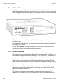
1.3 Advisor T3 ...............................................................................................................................26
1.3.1 General Description ..................................................................................................................................... 26
1.3.2 Features ........................................................................................................................................................ 27
General ...........................................................................................................................................................................
Flexible 3.0 Calibration..................................................................................................................................................
Physical Components ...................................................................................................................................................
Recording Options ........................................................................................................................................................
Display Options .............................................................................................................................................................
27
27
27
28
28
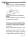
1.4 Mercury T2...............................................................................................................................30
1.4.1 General Description ..................................................................................................................................... 30
1.4.2 Features ........................................................................................................................................................ 31
General ...........................................................................................................................................................................
Physical Components ...................................................................................................................................................
Recording Options ........................................................................................................................................................
Display Options .............................................................................................................................................................
USB Protocol Suite User Manual
31
31
31
32
3
Teledyne LeCroy Corporation
Contents
1.5 Voyager M3x Analyzer............................................................................................................ 33
1.5.1 USB 2.0 and USB 3.0 Features ................................................................................................................... 33
1.5.2 General Description ..................................................................................................................................... 34
1.5.3 Features ........................................................................................................................................................ 35
General ...........................................................................................................................................................................
Flexible 3.0 Calibration..................................................................................................................................................
Physical Components ...................................................................................................................................................
Recording Options ........................................................................................................................................................
Display Options .............................................................................................................................................................
35
35
35
35
36
1.5.4 Traffic Generation ........................................................................................................................................ 37
ReadyLink™ Emulation................................................................................................................................................. 37
1.5.5 Notes on LFPS Signals................................................................................................................................ 38
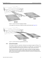
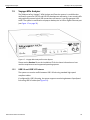
1.6 USBTracer/Trainer, USB Advisor, USBMobile HS and USBMobile T2 ............................... 38
Chapter 2: General Description ............................................................................ 39
2.1 Voyager M3/M3i Analyzer....................................................................................................... 39
2.1.1 System Components and Packing List...................................................................................................... 39
2.1.2 Host Machine Requirements....................................................................................................................... 39
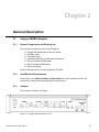
2.1.3 Analyzer ........................................................................................................................................................ 39
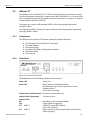
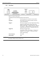
2.1.4 Specifications............................................................................................................................................... 42
Power Requirements .....................................................................................................................................................
Environmental Conditions ............................................................................................................................................
Probing Characteristics ................................................................................................................................................
Switches .........................................................................................................................................................................
Recording Memory Size ................................................................................................................................................
42
42
42
42
42
2.2 Advisor T3 ............................................................................................................................... 43
2.2.1 Components ................................................................................................................................................. 43
2.2.2 Front Panel ................................................................................................................................................... 43
2.2.3 Rear Panel .................................................................................................................................................... 44
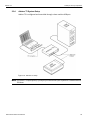
2.2.4 Advisor T3 System Setup............................................................................................................................ 45
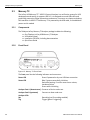
2.3 Mercury T2............................................................................................................................... 46
2.3.1 Components ................................................................................................................................................. 46
2.3.2 Front Panel ................................................................................................................................................... 46
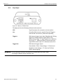
2.3.3 Rear Panel .................................................................................................................................................... 47
2.3.4 Mercury T2 System Setup ........................................................................................................................... 48
2.4 Voyager M3x Analyzer............................................................................................................ 49
2.4.1 System Components and Packing List...................................................................................................... 49
2.4.2 Host Machine Requirements....................................................................................................................... 49
2.4.3 Analyzer ........................................................................................................................................................ 49
2.4.4 Specifications............................................................................................................................................... 51
Power Requirements .....................................................................................................................................................
Environmental Conditions ............................................................................................................................................
Probing Characteristics ................................................................................................................................................
Switches .........................................................................................................................................................................
Recording Memory Size ................................................................................................................................................
51
52
52
52
52
2.5 USBTracer/Trainer, USB Advisor, USBMobile HS and USBMobile T2 ............................... 53
4
USB Protocol Suite User Manual
Contents
Teledyne LeCroy Corporation
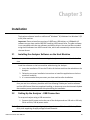
Chapter 3: Installation............................................................................................ 55
3.1 Installing the Analyzer Software on the Host Machine .......................................................55
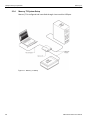
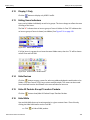
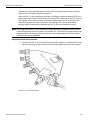
3.2 Setting Up the Analyzer - USB Connection.......................................................................... 55
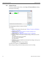
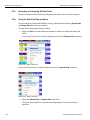
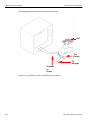
3.3 Setting Up the Analyzer - Ethernet Connection................................................................... 56
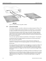
3.4 Cascading with CATC SYNC Expansion Card .....................................................................57
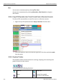
3.4.1 Capturing USB 2.0 traffic with CATC Sync or Cross Sync ...................................................................... 57
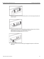
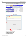
3.4.2 Removing Expansion Cards ....................................................................................................................... 58
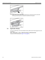
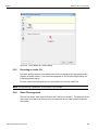
3.5 Application Startup................................................................................................................. 60
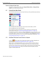
3.5.1 Confirm Proper Hardware Installation and USB or Ethernet Connection .............................................. 61
USB Connection ............................................................................................................................................................ 61
Ethernet Connection (Voyager only) ........................................................................................................................... 61
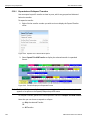
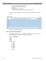
3.5.2 Analyzer Devices ......................................................................................................................................... 62
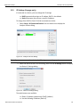
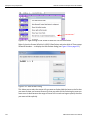
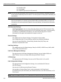
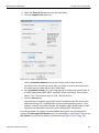
3.5.3 IP Settings (Voyager only) .......................................................................................................................... 63
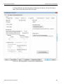
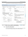
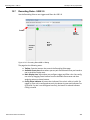
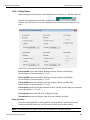
3.5.4 Analyzer Network ......................................................................................................................................... 64
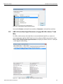
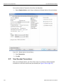
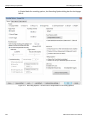
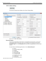
3.5.5 USB 3.0 Device/Host Signal Parameters (Voyager M3, M3i, Advisor T3 and M3x) ................................ 65
Input Equalization.......................................................................................................................................................... 67
3.5.6 USB 3.0 Cabling and Signal Integrity ......................................................................................................... 68
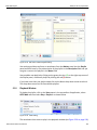
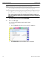
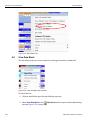
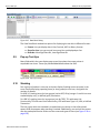
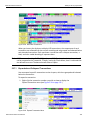
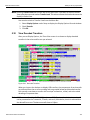
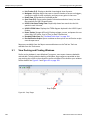
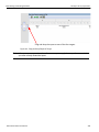
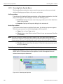
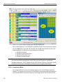
3.6 Your First USB Recording...................................................................................................... 68
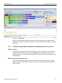
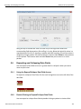
3.6.1 Trace View Features .................................................................................................................................... 70
3.7 Notes on Windows 7 and Windows 8 Directory Protections.............................................. 71
3.7.1 User Data File Paths .................................................................................................................................... 71
3.8 Notes on Windows Sleep and Hibernation Features........................................................... 71
Chapter 4: Software Overview................................................................................ 73
4.1 Starting the Program .............................................................................................................. 73
4.2 The Main Display Window...................................................................................................... 74
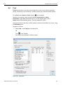
4.2.1 Exports to .CSV ............................................................................................................................................ 81
Export Packets to .CSV ................................................................................................................................................. 81
Export Transactions to .CSV ........................................................................................................................................ 81
Export Spreadsheet View to .CSV................................................................................................................................ 81
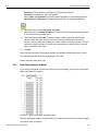
4.2.2 Exporting Packets to USB 2.0 Host Traffic Generator Text File (.utg files)............................................ 81
4.3 Tool Bar ................................................................................................................................... 83
4.3.1 Files, Searches, and Options ...................................................................................................................... 83
4.3.2 Zoom and Wrap ............................................................................................................................................ 84
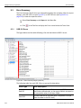
4.3.3 Miscellaneous .............................................................................................................................................. 84
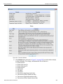
4.3.4 Analysis (Reports) ...................................................................................................................................... 84
4.3.5 Recording ..................................................................................................................................................... 86
4.3.6 Generator (Traffic Generation for USB 3) .................................................................................................. 86
4.3.7 Generator (Traffic Generation for USB 2) .................................................................................................. 87
4.3.8 View Level..................................................................................................................................................... 87
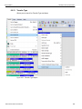
4.3.9 Trace Views .................................................................................................................................................. 87
USB 2.0 USB 3.0 Show ................................................................................................................................................. 88
Hiding Traffic (2.0 & 3.0)................................................................................................................................................ 88
USB Protocol Suite User Manual
5
Teledyne LeCroy Corporation
Contents
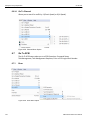
4.4 Tooltips .................................................................................................................................... 91
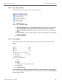
4.5 View Options ........................................................................................................................... 92
4.5.1 Resetting the Toolbar .................................................................................................................................. 92
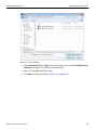
4.6 Status Bar ................................................................................................................................ 93
4.6.1 Recording Progress..................................................................................................................................... 93
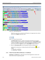
4.6.2 Recording Status ......................................................................................................................................... 94
4.6.3 Recording Activity ....................................................................................................................................... 96
4.6.4 Search Status ............................................................................................................................................... 96
4.6.5 SuperSpeed Termination Status ................................................................................................................ 96
4.6.6 Link Status.................................................................................................................................................... 97
4.7 Navigation Tools ..................................................................................................................... 98
4.7.1 Zoom In ......................................................................................................................................................... 98
4.7.2 Zoom Out ...................................................................................................................................................... 98
4.7.3 Wrap .............................................................................................................................................................. 98
4.8 CrossSync Control Panel....................................................................................................... 98
4.8.1 Launching the CrossSync Control Panel .................................................................................................. 98
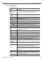
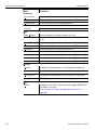
4.9 Analyzer Keyboard Shortcuts ............................................................................................. 100
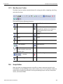
Chapter 5: Reading a Trace ................................................................................. 103
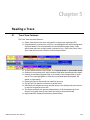
5.1 Trace View Features .............................................................................................................103
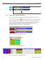
5.1.1 Anchor Points - Synchronized Views....................................................................................................... 104
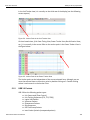
5.1.2 USB 3.0 Packets ......................................................................................................................................... 105
5.1.3 Packet Direction ......................................................................................................................................... 106
5.2 Markers .................................................................................................................................. 106
5.2.1 Markers Overview ...................................................................................................................................... 106
5.2.2 Functionality of Markers ........................................................................................................................... 106
5.2.3 Attaching Markers...................................................................................................................................... 108
5.2.4 Adding an Attachment............................................................................................................................... 108
5.2.5 Recording an Audio File............................................................................................................................ 109
5.2.6 Video Files supported ............................................................................................................................... 109
5.2.7 Attachment Types and Visualization........................................................................................................ 110
5.2.8 Embedded Attachments to a Marker........................................................................................................ 110
5.2.9 Viewing Attachments of a Marker ............................................................................................................ 110
Text ...............................................................................................................................................................................
Audio.............................................................................................................................................................................
Video .............................................................................................................................................................................
File Attachment............................................................................................................................................................
URL Link .......................................................................................................................................................................
YouTube Video.............................................................................................................................................................
Images ..........................................................................................................................................................................
Other Attachments ......................................................................................................................................................
111
112
113
113
113
114
114
114
5.2.10 Edit Marker ............................................................................................................................................... 115
5.2.11 All Markers Window ................................................................................................................................. 116
5.3 CATC Walk Playlist ............................................................................................................... 117
5.3.1 Playlist Functionality ................................................................................................................................. 118
6
USB Protocol Suite User Manual
Contents
Teledyne LeCroy Corporation
5.3.2 Playback Window....................................................................................................................................... 119
Playlist Playback Controls.......................................................................................................................................... 120
5.4 Time Stamp............................................................................................................................ 121
5.5 View Raw Bits (2.0) ............................................................................................................... 122
5.6 Expanding and Collapsing Data Fields............................................................................... 123
5.6.1 Using the Expand/Collapse Data Field Arrows ....................................................................................... 123
5.6.2 Double-Clicking to Expand/Collapse Data Fields ................................................................................... 123
5.6.3 Expanding or Collapsing All Data Fields ................................................................................................. 124
5.6.4 Using the Data Field Pop-up Menus......................................................................................................... 124
Expand or Collapse All Data Fields ........................................................................................................................... 125
5.7 Format/Color/Hide Fields ..................................................................................................... 125
5.7.1 Hide/Show Field when Packet Section is Collapsed .............................................................................. 125
5.8 View Data Block ....................................................................................................................126
5.9 Pop-up Tool-tips ................................................................................................................... 127
5.10 Stacking ............................................................................................................................... 127
5.11 Display 2 Only ..................................................................................................................... 128
5.12 Display 3 Only ..................................................................................................................... 129
5.13 Hiding Items Indicators ......................................................................................................129
5.14 Hide Devices ....................................................................................................................... 129
5.15 Hide All Packets Except Transfers Packets. .................................................................... 129
5.16 Hide NAKs ...........................................................................................................................129
5.17 Hide SOF Packets (2.0)....................................................................................................... 130
5.18 Hide Chirps (2.0) ................................................................................................................. 130
5.19 Hide Upstream Packets (3.0).............................................................................................. 130
5.20 Hide Downstream Packets (3.0) ........................................................................................130
5.21 Hide Link Training Sequences (3.0) .................................................................................. 130
5.22 Hide Link Commands (Flow Control) (3.0) ....................................................................... 130
5.23 Hide Bus Events (3.0) ......................................................................................................... 131
5.24 Hide Miscellaneous Packets (3.0) ..................................................................................... 131
5.25 Hide All Transactions Except Stream Id Numbers .......................................................... 131
5.26 Switch to Transactions View ............................................................................................. 133
5.27 View Decoded Transactions .............................................................................................. 134
5.27.1 Expanded and Collapsed Transactions ................................................................................................. 135
5.28 Switch to Split Transaction View....................................................................................... 136
5.29 Switch to Transfer View ..................................................................................................... 136
5.30 View Decoded Transfers ....................................................................................................137
5.30.1 Expanded and Collapsed Transfers ....................................................................................................... 138
5.31 Decoding Protocol-Specific Fields in Transactions and Transfers ............................... 139
5.32 Switch to PTP Transactions...............................................................................................139
5.33 Switch to PTP Object Transfers ........................................................................................139
5.34 Switch to PTP Sessions ..................................................................................................... 140
USB Protocol Suite User Manual
7
Teledyne LeCroy Corporation
Contents
5.35 Switch to SCSI Operations ................................................................................................ 141
5.35.1 SCSI Metrics ............................................................................................................................................. 141
5.36 Compressed CATC Trace View.......................................................................................... 141
5.37 Spreadsheet View ............................................................................................................... 142
5.37.1 Columns.................................................................................................................................................... 144
5.37.2 Rows ......................................................................................................................................................... 144
5.37.3 Detail View and Spreadsheet View ......................................................................................................... 146
5.38 Edit Comment ..................................................................................................................... 147
Chapter 6: Searching Traces............................................................................... 149
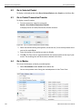
6.1 Go to Trigger ......................................................................................................................... 149
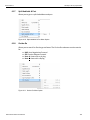
6.2 Go to Selected Packet .......................................................................................................... 150
6.3 Go to Packet/Transaction/Transfer ..................................................................................... 150
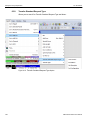
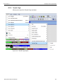
6.4 Go to Marker.......................................................................................................................... 150
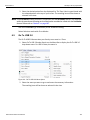
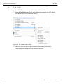
6.5 Go To USB 2.0 ....................................................................................................................... 151
6.5.1 Packet IDs (PIDs) ....................................................................................................................................... 152
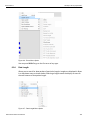
6.5.2 ANY Error.................................................................................................................................................... 152
6.5.3 Errors .......................................................................................................................................................... 152
6.5.4 Data Length ................................................................................................................................................ 153
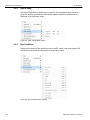
6.5.5 Addr & Endp ............................................................................................................................................... 154
6.5.6 Bus Conditions .......................................................................................................................................... 154
6.5.7 Split HubAddr & Port ................................................................................................................................. 155
6.5.8 On-the-Go ................................................................................................................................................... 155
6.5.9 Transfer Standard Request Type ............................................................................................................. 156
6.5.10 Transfer Type ........................................................................................................................................... 157
6.6 Go To USB3.0 ........................................................................................................................ 158
6.6.1 Packet Type ................................................................................................................................................ 159
6.6.2 LFPS Type .................................................................................................................................................. 160
6.6.3 Deferred Packet.......................................................................................................................................... 161
6.6.4 ANY Error161
6.6.5 Specific Errors ........................................................................................................................................... 162
6.6.6 Data Length ................................................................................................................................................ 163
6.6.7 Address and Endpoint............................................................................................................................... 164
6.6.8 Header Packet Type ................................................................................................................................... 164
6.6.9 Link Command ........................................................................................................................................... 165
6.6.10 LMP Subtype ............................................................................................................................................ 166
6.6.11 Transaction Packet Type......................................................................................................................... 167
6.6.12 Transfer Standard Request Type ........................................................................................................... 168
6.6.13 Transfer Type ........................................................................................................................................... 169
6.6.14 Go To Channel ......................................................................................................................................... 170
6.7 Go To SCSI ............................................................................................................................ 170
6.7.1 Error ............................................................................................................................................................ 170
8
USB Protocol Suite User Manual
Contents
Teledyne LeCroy Corporation
6.8 Find ........................................................................................................................................ 171
6.8.1 Data Pattern Mask and Match ................................................................................................................... 173
6.9 Find Next ............................................................................................................................... 174
6.10 Search Direction ................................................................................................................. 174
6.11 Protocol ............................................................................................................................... 174
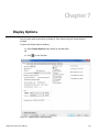
Chapter 7: Display Options ................................................................................. 175
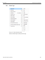
7.1 General Display Options ......................................................................................................176
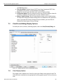
7.2 Color/Format/Hiding Display Options.................................................................................177
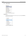
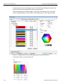
7.2.1 Color Display Options ............................................................................................................................... 177
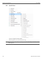
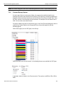
7.2.2 Formats Display Options .......................................................................................................................... 179
7.2.3 Hiding Display Options ............................................................................................................................. 180
7.3 USB 2.0 Packet Hiding Options........................................................................................... 180
7.4 USB 3.0 Packet Hiding Options........................................................................................... 181
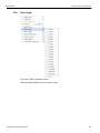
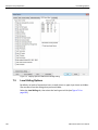
7.5 Level Hiding Options............................................................................................................ 182
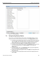
7.6 Saving/Loading Display Options......................................................................................... 183
7.7 Restore Factory Setting ....................................................................................................... 184
Chapter 8: Decode Requests .............................................................................. 185
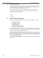
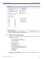
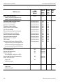
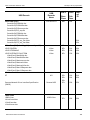
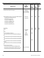
8.1 Class and Vendor Definition Files....................................................................................... 185
8.2 Class/Vendor Decoding Options ......................................................................................... 191
8.2.1 Mapping Request Recipient to Class/Vendor Decoding ........................................................................ 191
8.2.2 Mapping Endpoint to Class/Vendor Decoding ........................................................................................ 193
8.3 General Options....................................................................................................................199
8.3.1 Decoding USB Device Requests .............................................................................................................. 199
8.3.2 Decoding Standard Requests ................................................................................................................... 200
8.3.3 Decoding Class Requests ......................................................................................................................... 201
8.3.4 Decoding Vendor Requests ...................................................................................................................... 201
8.3.5 Decoding Undefined USB/WUSB Device Requests................................................................................ 202
8.3.6 Decoding using Endpoint Information..................................................................................................... 202
8.3.7 Changing the Layout of Decode Requests.............................................................................................. 203
8.3.8 Decoded Fields View ................................................................................................................................. 204
Chapter 9: Reports ............................................................................................... 207
9.1 View Docking and Floating Windows. ................................................................................ 208
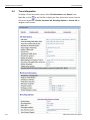
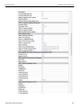
9.2 Trace Information.................................................................................................................. 210
9.3 Error Summary...................................................................................................................... 214
9.3.1 USB 2.0 Errors............................................................................................................................................ 214
9.3.2 USB 3.0 Errors............................................................................................................................................ 216
9.4 Timing Calculations.............................................................................................................. 218
USB Protocol Suite User Manual
9
Teledyne LeCroy Corporation
Contents
9.5 Data View ............................................................................................................................... 221
9.6 Traffic Summary Report ....................................................................................................... 222
9.6.1 SCSI Metrics ............................................................................................................................................... 223
9.7 Bus Utilization....................................................................................................................... 224
9.7.1 Bus Utilization Buttons ............................................................................................................................. 225
9.7.2 View Settings Menu ................................................................................................................................... 226
9.7.3 Graph Areas Menu ..................................................................................................................................... 228
Change the Properties in the Bus Utilization Graph ................................................................................................ 229
Creating a New Bus Utilization Graph ....................................................................................................................... 230
9.8 Link Tracker (3.0) .................................................................................................................. 231
9.8.1 Using the Link Tracker Window ............................................................................................................... 232
Zooming In and Out.....................................................................................................................................................
Collapsing Idle Time, Enabling Tool tips, and Resetting Column Widths .............................................................
Docking and Undocking the Window ........................................................................................................................
Setting Markers............................................................................................................................................................
Hiding Traffic................................................................................................................................................................
232
232
233
233
233
9.8.2 Link Tracker Buttons ................................................................................................................................. 234
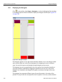
9.9 Using the Navigator.............................................................................................................. 235
9.9.1 Displaying the Navigator ........................................................................................................................... 236
9.9.2 Navigator Toolbar ...................................................................................................................................... 237
9.9.3 Navigator Ranges ...................................................................................................................................... 237
To Determine Current Position................................................................................................................................... 238
To Reset Navigator Range .......................................................................................................................................... 238
9.9.4 Navigator Panes ......................................................................................................................................... 239
To Show/Hide Navigator Panes..................................................................................................................................
Navigator Slider ...........................................................................................................................................................
Navigator Legend ........................................................................................................................................................
Using the Legend to Show/Hide Navigator Panes....................................................................................................
Using the Legend to Set the Priority of Information Display...................................................................................
239
240
240
241
241
9.10 Detail View ...........................................................................................................................242
9.10.1 Detail View and Spreadsheet View ......................................................................................................... 242
9.11 Spec View (3.0)....................................................................................................................243
9.12 USB 3.0 Link State Timing View ........................................................................................244
9.12.1 USB 3.0 Link State Timing View Toolbar ............................................................................................... 244
9.12.2 USB 3.0 LTSSM View ............................................................................................................................... 246
9.13 Power Tracker ..................................................................................................................... 247
9.13.1 Power Tracker Toolbar ............................................................................................................................ 248
9.13.2 Decoded Fields view................................................................................................................................ 249
9.13.3 Running Verification Scripts................................................................................................................... 249
9.14 Real Time Monitoring ......................................................................................................... 253
9.14.1 Real-Time Statistics Buttons .................................................................................................................. 254
9.14.2 Real-Time Statistical Monitor Pop-up Menu .......................................................................................... 255
9.14.3 Displaying Multiple Graphs..................................................................................................................... 256
10
USB Protocol Suite User Manual
Contents
Teledyne LeCroy Corporation
Chapter 10: Recording Options .......................................................................... 257
10.1 Recording Options Modes ................................................................................................. 258
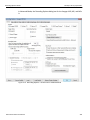
10.2 General Recording Options ...............................................................................................265
10.2.1 Product ..................................................................................................................................................... 266
10.2.2 Trigger Mode ............................................................................................................................................ 266
Snapshot ...................................................................................................................................................................... 266
Manual Trigger ............................................................................................................................................................. 266
Event Trigger................................................................................................................................................................ 267
10.2.3 Recording Channels (Voyager and Advisor T3).................................................................................... 267
10.2.4 Recording Scope (Voyager, Advisor T3 and Mercury T2).................................................................... 267
10.2.5 Buffer Size ................................................................................................................................................ 268
10.2.6 Trigger Position ....................................................................................................................................... 268
10.2.7 Options Name........................................................................................................................................... 268
10.2.8 Trace File Name & Path ........................................................................................................................... 269
10.2.9 VBus Power .............................................................................................................................................. 270
10.2.10 CATC Sync (Voyager and AdvisorT3 only).......................................................................................... 270
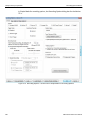
10.3 Recording Options-Misc. USB 2.0..................................................................................... 270
10.3.1 Analyzer Trace Speed.............................................................................................................................. 272
Notes on Hi Speed Recordings .................................................................................................................................. 272
10.3.2 Generator/Analyzer Clocking Overrides ................................................................................................ 273
10.3.3 USB On-The-Go........................................................................................................................................ 273
10.3.4 Generator-related Parameters ................................................................................................................ 273
10.3.5 Data Truncation Option ........................................................................................................................... 273
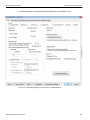
10.4 Recording Options - Misc. USB 3.0 for Voyager.............................................................. 274
10.4.1 Very Slow Clock Usage (Voyager M3/M3i ONLY).................................................................................. 277
External Clock Input Specifications........................................................................................................................... 279
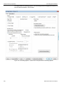
10.5 Recording Options - Misc. USB 3.0 for Advisor T3 ......................................................... 280
10.6 Recording Rules Actions and Action Properties............................................................. 281
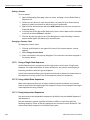
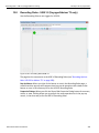
10.7 Recording Rules - USB 2.0 ................................................................................................ 283
10.7.1 Recording Rules Toolbar ........................................................................................................................ 284
10.7.2 Recording Rules Page: How It Works .................................................................................................... 286
10.7.3 Creating Event Buttons ........................................................................................................................... 287
10.7.4 Dragging a Button to the Main Display Area ......................................................................................... 288
10.7.5 Assigning an Action ................................................................................................................................ 289
10.7.6 Recording Rules Pop-Up Menus ............................................................................................................ 290
Cell Pop-up Menu ........................................................................................................................................................ 290
Action Pop-up Menu.................................................................................................................................................... 290
Event Pop-up Menu ..................................................................................................................................................... 291
10.7.7 Events and Event Properties for USB 2.0 .............................................................................................. 292
Event Properties (of the Error Event) ........................................................................................................................ 293
Data Pattern Mask and Match..................................................................................................................................... 294
10.7.8 Counters and Timers for USB 2.0........................................................................................................... 296
Events and Actions ..................................................................................................................................................... 296
Number of Analyzer Counters and Timers................................................................................................................ 297
Packets ......................................................................................................................................................................... 297
USB Protocol Suite User Manual
11
Teledyne LeCroy Corporation
Contents
Using a Counter ........................................................................................................................................................... 297
Setting a Counter......................................................................................................................................................... 298
Changing a Counter Value.......................................................................................................................................... 298
10.7.9 Using a Single-State Sequence .............................................................................................................. 298
10.7.10 Using a Multi-State Sequences............................................................................................................. 298
10.7.11 Using Independent Sequences............................................................................................................. 298
10.8 Recording Rules - USB 3.0 (Voyager/Advisor T3 only) ................................................... 299
10.8.1 Recording Rules Toolbar ........................................................................................................................ 300
10.8.2 Recording Rules Page: How It Works .................................................................................................... 300
10.8.3 Creating Event Buttons ........................................................................................................................... 300
10.8.4 Dragging a Button to the Main Display Area ......................................................................................... 302
10.8.5 Assigning an Action ................................................................................................................................ 303
10.8.6 Recording Rules Pop-Up Menus ............................................................................................................ 303
Cell Pop-up Menu ........................................................................................................................................................ 303
Event Pop-up Menu ..................................................................................................................................................... 303
Action Pop-up Menu.................................................................................................................................................... 303
10.8.7 Actions and Action Properties ............................................................................................................... 303
Action Properties......................................................................................................................................................... 303
10.8.8 Events and Event Properties for USB 3.0 .............................................................................................. 304
10.8.9 Counters and Timers for USB 3.0........................................................................................................... 308
10.8.10 Configuration Validity............................................................................................................................ 310
10.9 Saving Recording Options................................................................................................. 310
10.10 Recording Bus Data ......................................................................................................... 310
10.11 Merging Trace Files .......................................................................................................... 311
10.12 Recording Option Summary Tab..................................................................................... 314
Chapter 11: Traffic Generation 2.0 ...................................................................... 315
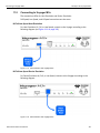
11.1 Connecting to Voyager M3/M3i.......................................................................................... 315
Hi/Full/Low Speed Host Emulation ............................................................................................................................ 315
Hi/Full/Low Speed Device Emulation......................................................................................................................... 316
11.2 Connecting to Voyager M3x...............................................................................................317
Hi/Full/Low Speed Host Emulation ............................................................................................................................ 317
Hi/Full/Low Speed Device Emulation......................................................................................................................... 317
11.3 Traffic Generation Files ......................................................................................................318
11.4 Creating Traffic Generation Files ...................................................................................... 318
11.4.1 Creating a Traffic Generation File with the Export Command............................................................. 319
11.5 Editing a Generation File.................................................................................................... 320
11.5.1 Toolbar ...................................................................................................................................................... 322
11.5.2 View Options Menu .................................................................................................................................. 323
11.5.3 Pop-up Menu ............................................................................................................................................ 323
11.5.4 File Tabs ................................................................................................................................................... 324
11.5.5 Error Log................................................................................................................................................... 324
11.5.6 Tooltips ..................................................................................................................................................... 324
11.6 Loading the Generation File .............................................................................................. 324
11.6.1 Traffic Generation Modes: Bitstream vs. Intelliframe........................................................................... 327
12
USB Protocol Suite User Manual
Contents
Teledyne LeCroy Corporation
11.7 Starting Traffic Generation................................................................................................. 327
11.8 Repeating a Generation Session....................................................................................... 327
11.9 Stop Traffic Generation ......................................................................................................328
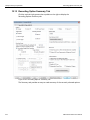
11.10 Device Emulation .............................................................................................................. 328
11.10.1 Creating a Generation File .................................................................................................................... 328
11.10.2 Setting Generation Options .................................................................................................................. 328
11.10.3 Run the Traffic Generation Script File ................................................................................................. 329
11.11 Voyager M3x USB 2.0 Script Limitations ........................................................................ 329
11.12 Format of Traffic Generation Files .................................................................................. 330
11.12.1 Script Control of Intelliframe vs Bitstream modes ............................................................................. 331
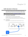
Chapter 12: Traffic Generation 3.0 Exerciser .................................................... 349
12.1 Connecting to Voyager M3/M3i.......................................................................................... 349
12.1.1 Host Emulation......................................................................................................................................... 349
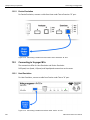
12.1.2 Device Emulation ..................................................................................................................................... 350
12.2 Connecting to Voyager M3x...............................................................................................350
12.2.1 Host Emulation......................................................................................................................................... 350
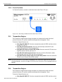
12.2.2 Device Emulation ..................................................................................................................................... 351
12.3 Transaction Engine.............................................................................................................351
12.4 Transaction Engine.............................................................................................................351
12.5 Exerciser Files ....................................................................................................................352
12.6 Creating Exerciser Files..................................................................................................... 352
12.7 Exerciser Window............................................................................................................... 352
12.7.1 Exerciser Menus ...................................................................................................................................... 353
12.7.2 Main Exerciser Toolbar ........................................................................................................................... 355
12.8 Script Editor ........................................................................................................................ 355
12.8.1 Highlighting .............................................................................................................................................. 356
12.8.2 Text Editing Commands .......................................................................................................................... 356
12.8.3 Help ........................................................................................................................................................... 356
12.8.4 Properties Window .................................................................................................................................. 356
12.8.5 File Tabs ................................................................................................................................................... 356
12.8.6 Errors ........................................................................................................................................................ 356
12.8.7 Output ....................................................................................................................................................... 357
12.8.8 Options Menu ........................................................................................................................................... 357
12.8.9 Outlining ................................................................................................................................................... 357
12.8.10 Line Numbers ......................................................................................................................................... 357
12.8.11 Tooltips ................................................................................................................................................... 357
12.8.12 Text Snippets ......................................................................................................................................... 357
12.8.13 Views Toolbar......................................................................................................................................... 359
12.8.14 Script Toolbar......................................................................................................................................... 359
12.8.15 Pop-up Menu .......................................................................................................................................... 360
12.8.16 Error Log................................................................................................................................................. 360
12.8.17 Tooltips ................................................................................................................................................... 360
USB Protocol Suite User Manual
13
Teledyne LeCroy Corporation
Contents
12.9 Creating a Script using the Script Editor ......................................................................... 361
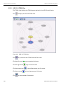
12.10 Graphical Scenario Editor................................................................................................363
12.10.1 Graphical Scenario Window ................................................................................................................. 364
12.10.2 Initiator Setting....................................................................................................................................... 367
Device Information ......................................................................................................................................................
SCSI Command Settings.............................................................................................................................................
General Settings ..........................................................................................................................................................
Link Delay Settings......................................................................................................................................................
Link Power Management Settings .............................................................................................................................
LFPS Settings ..............................................................................................................................................................
Link Configuration Settings........................................................................................................................................
367
368
368
368
368
368
368
12.10.3 Option Button ......................................................................................................................................... 369
Script Scenarios .......................................................................................................................................................... 369
Save .............................................................................................................................................................................. 370
12.10.4 Copy SCSI Operation from Trace File and Paste to Exerciser Scenario .......................................... 370
12.10.5 Graphical Toolbar .................................................................................................................................. 370
12.11 Loading and Running the Generation File ..................................................................... 371
12.11.1 Starting Traffic Generation ................................................................................................................... 371
12.11.2 Stop Traffic Generation ......................................................................................................................... 371
12.12 Exporting a Trace to a Traffic Generation File ............................................................... 371
12.13 USB 3.0 Electrical Test Modes......................................................................................... 373
12.13.1 Loopback Mode...................................................................................................................................... 373
12.13.2 Compliance Mode .................................................................................................................................. 376
Compliance Mode test procedure .............................................................................................................................. 377
Chapter 13: Updates ............................................................................................ 387
13.1 Software, Firmware, and BusEngine Revisions .............................................................. 387
13.2 Software Updates................................................................................................................ 388
13.2.1 Manual Check for Software Updates...................................................................................................... 388
13.2.2 Automatic Check for Software Updates................................................................................................. 389
During Software Installation ....................................................................................................................................... 390
In the Application......................................................................................................................................................... 391
13.3 BusEngine and Firmware Updates ................................................................................... 392
13.3.1 Updating the BusEngines ....................................................................................................................... 392
13.3.2 Updating the Firmware ............................................................................................................................ 392
13.3.3 Automatic Updates .................................................................................................................................. 392
13.3.4 Manual Updates to Firmware, BusEngine, and Serdes BusEngine .................................................... 392
13.4 License Information............................................................................................................ 393
13.5 Updating the Software License ......................................................................................... 394
13.6 Registering Online.............................................................................................................. 395
13.7 Shortcut List........................................................................................................................ 396
13.8 Video Tutorials ....................................................................................................................398
14
USB Protocol Suite User Manual
Contents
Teledyne LeCroy Corporation
Appendix A: China Restriction of Hazardous Substances Table .................... 399
Appendix B: Contacting Teledyne LeCroy......................................................... 401
Index:.................................................................................................................. 403
USB Protocol Suite User Manual
15
Teledyne LeCroy Corporation
16
Contents
USB Protocol Suite User Manual
Chapter 1
Overview
1.1
Common Features
1.1.1
Graphical Bus Traffic Display
Bus traffic displays use color and graphics to show captured transactions.
Packets are on separate rows. Packets receive time stamps and sequential numbers as the system records them. Fields have labels and color codes. The system automatically detects protocol errors and highlights them in red.
You can customize the display color scheme and field formats. You can use the hide feature to suppress SOF packets and uninteresting user‐defined packets or fields in different contexts. You can name and save display formats for later use. Pop‐up tooltips annotate packet fields.
The display software operates independently of the hardware, allowing it to function as a stand‐alone “trace viewer” that you can freely distribute.
Figure 1.1: Trace Viewer
USB Protocol Suite User Manual
17
Teledyne LeCroy Corporation
1.1.2
Common Features
Accurate Time Measurement (Voyager, Advisor T3)
The internal counter/timer circuitry enables reliable, accurate (2 ns resolution) time stamping of recorded bus traffic. Traces and measurement and analysis functions display this timing information. Time fields are time stamps, idle times, bit times, or time deltas, in either decimal or hexadecimal format. You can add any number of markers to denote specific packets, you can make further timing measurements from one marker to another or from marker to trigger.
An essential feature of time management is that idle traffic does not consume Analyzer memory. Because of this unique technology, the system can make accurate timing calculations while still preserving valuable recording memory for important bus traffic.
The oscillator has 2.5 ppm accuracy.
1.1.3
CrossSync Control Panel (Voyager, Advisor T3)
The CrossSync Control Panel allows you to select analyzers for synchronization and manage the recording process. It supports a wide combination of Teledyne LeCroy’s flagship analyzers including PCI Express Gen 1, Gen 2 and Gen 3; USB 2.0 and 3.0; Serial ATA (SATA) 1.5, 3 and 6Gbps; Serial Attached SCSI (SAS) 6Gbps and Fibre Channel 1. 2, 4 and 8Gbps systems. CrossSync is Teledyne LeCroy’s analyzer synchronization solution that enables time‐
aligned display of protocol traffic from multiple daisy‐chained analyzers showing packet traffic from multiple high‐speed serial busses. A lightweight software control panel allows users to select analyzers for synchronization and manage the recording process. Captured traffic is displayed using the latest analyzer software (in separate windows) with all the protocol specific search and reporting features.
Captured packets are displayed in separate windows that share a common time scale. Navigating the traffic in either direction will scroll to the same timestamp in a synchronized window. When using the CrossSync option, users can access the full complement of analysis capabilities available within the individual Teledyne LeCroy software. Search, reporting, and decoding all operate normally (see “CrossSync Control Panel” on page 98). This feature is available with the Teledyne LeCroy USB Protocol Suite application. 1.1.4
Comprehensive Error Detection and Analysis
The system detects, and alerts you to, every potential bus error and protocol violation, and their combinations. The Analyzer BusEngine™ circuitry performs real‐time triggering on multiple error conditions, such as PID bad, bit stuffing bad, header or data CRC bad, end‐of‐packet bad, babble, activity loss, frame length violation, time‐out or turn‐around violation, and data toggle violation. The Analyzer program highlights all hardware‐
detected errors and further examines the trace file for additional protocol errors, including wrong packet length, data payload violation, and packet termination not on a byte boundary.
18 USB Protocol Suite User Manual
Teledyne LeCroy Corporation
Common Features
1.1.5
Real-Time Event Triggering and Capture Filtering
The Analyzer can accurately identify and selectively record transactions of interest from the crowded stream of bus traffic. The system uses more than a dozen configurable hardware building blocks that you can optimize to perform particular activities. Such “recording resources” can independently await an initialization signal, monitor its external environment (external signals or other resources) in search of a particular event, and take a subsequent action, such as triggering, inclusive or exclusive filtering, and counting. In the user interface, you can select, configure, and combine these resources to search for complex trigger conditions and selectively capture associated transactions.
The system can trigger on basic events, such as specific bus conditions and packet identifiers (PID). It can also trigger on complex events, such as “trigger on the fifth occurrence of a SETUP Token device number nine” or “trigger on a SET INTERFACE request, following a specified eight‐byte bulk data pattern match from this scanner, and do not capture any start‐of‐frame (SOF) packets.”
You can set the size of the recording memory, specify the pre‐trigger to post‐trigger capture ratio, and truncate large data packets up to 256 bytes.
Advanced Event Counting and Sequencing
The count and sequence options define rules for data recording sessions. These options configure and control the order of events selected for triggering or filtering.
Using this feature, you can specify a sequence of up to seven events that must occur before the Analyzer triggers and finishes capturing data, allowing you to specify event types for recording. Without this feature, you may have to scroll through megabytes of recorded data to locate an occurrence of a sequence.
1.1.6
BusEngine Technology
The Analyzer uses Teledyne LeCroy BusEngine Technology. The BusEngine core uses Electrically Programmable Logic Device (EPLD) technology and incorporates both a real‐
time recording engine and configurable building blocks that implement data/state/error detection, triggering, capture filtering, external signal monitoring, and event counting and sequencing. Like the flash‐memory‐based firmware that controls its operation, all BusEngine logic is fully field upgradeable, using configuration files.
USB Protocol Suite User Manual
19
Teledyne LeCroy Corporation
1.2
Voyager M3/M3i Analyzer
Voyager M3/M3i Analyzer
The Teledyne LeCroy Voyager™ M3/M3i Analyzer and Exerciser system is a multifunction verification system for USB 2.0 and USB 3.0 development and testing. It can record traffic and graphically present logical USB transactions and events. It can also generate USB traffic. The system is connected to a laptop or desktop via its USB or Gigabit Ethernet port (see Figure 1.2 on page 20).
Note: The Voyager M3 and Voyager M3i Analyzer and Exerciser are identical in most respects. The major difference is that Voyager M3i can capture VBus Power information. Otherwise, all mentions of Voyager M3 in this manual also apply to Voyager M3i.
Figure 1.2: Voyager M3/M3i Analyzer Exerciser System
Please see the Readme file on the installation CD for the latest information on host machine requirements and supported operating systems.
1.2.1
USB 2.0 and USB 3.0 Features
The system can monitor traffic between USB 2.0 links using standard high‐speed compliant cables. If configured for USB 3.0 testing, the system supports monitoring between SuperSpeed links using USB 3.0 cables (see Figure 1.3 on page 21)
20 USB Protocol Suite User Manual
Voyager M3/M3i Analyzer
Teledyne LeCroy Corporation
Figure 1.3: Direct Connection using USB 3.0 Cables
or through direct connection via MMCX‐to‐SMA coaxial cables (see Figure 1.4).
Figure 1.4: Direct Connection using SMA Differential Tap
1.2.2
General Description
The Analyzer connects to a portable or desktop host machine through the USB port. The host machine configures and controls the Analyzer. The “CATC Trace™” user interface is an industry standard for documenting the performance of high‐speed serial protocols. The USB protocol Analyzer provides traffic capture and analysis. Hardware triggering allows capture of real‐time events. Hardware filtering allows filtering different packet types in or out of the recording. Filtering also allows you to preserve recording memory, for extended recording time.
USB Protocol Suite User Manual
21
Teledyne LeCroy Corporation
Voyager M3/M3i Analyzer
The trace viewer application displays recorded data in colored graphics. The application has advanced search and viewing capabilities that allow you to quickly locate specific data, errors, and other conditions. The system functions with any personal host machine having the Microsoft® Windows® XP, Windows 8, or Windows 7 (32 or 64) operating system and a functional USB interface or Ethernet port. The system provides on‐the‐fly detection of, and triggering on, such events as Tokens and Errors. Whether recording manually or with a specified trigger condition, the system continuously records the link data, in a wrap‐around fashion, until manually stopped or until the system detects the Trigger Event and records the specified post‐trigger amount of link data.
Upon detection of a triggering event, the Analyzer continues to record data up to a point specified by you. You can individually enable or disable real‐time event detection to allow triggering on events as they happen, including predefined exception or error conditions and user‐defined sets of trigger events. An externally supplied signal can trigger the Analyzer.
You can use search functions to investigate particular events. In addition to immediate analysis, you can print any part of the data. You can save the data on disk for later viewing. You can generate timing information and data analysis reports.
Please refer to the Universal Serial Bus Specification for details on the protocol. The USB specification is available from the USB Implementers Forum (USB‐IF) at:
USB Implementers Forum
1730 SW Skyline Blvd.
Suite 203
Portland, OR 97221
1.2.3
Tel: +1/503.296.9892
Fax: +1/503.297.1090
Web: http://www.usb.org/
Features
General
22 Fully complies with USB specification revisions.
Supports the Link Power Management extension.
Uses field‐upgradeable firmware and recording engine.
Supports all USB speeds (5 Gb/s, 480 Mb/s, 12 Mb/s, and 1.5 Mb/s).
Displays bus traffic using color and graphics in the user‐friendly CATC Trace inter‐
face.
Has free non‐recording, view‐only Trace Viewer software.
Comes with online manual.
Self‐diagnoses at power on.
Uses software upgradable Exerciser function.
Allows remote control of USB analyzers in a network.
USB Protocol Suite User Manual
Teledyne LeCroy Corporation
Voyager M3/M3i Analyzer
Flexible 3.0 Calibration
Each link can be calibrated with respect to received equalization and gain.
Physical Components
Desktop or portable Microsoft Windows XP, Windows 8, or Windows 7 (32 or 64) host machine with USB or Ethernet capability
Plug‐and‐Play USB installation
1 GB or 4 GB of physical data‐recording memory
USB 2.0 Hi‐Speed connection to desktop or portable host machine
Internal wide‐range AC power supply
Expansion port for future enhancements
SMA connectors and USB 3.0 connectors for SuperSpeed capture and generation
External clock inputs and outputs
Recording Options
Versatile triggering: bit‐wise value and mask data patterns up to sixteen bytes wide for Setup transactions and data packets
Triggering on new High‐Speed PIDs and split transaction special tokens (ERR, SPLIT, PING, NYET, DATA2, and MDATA) (2.0)
CATC Trace display and enumeration of High‐Speed Micro Frames (2.0)
Three forms of triggering: Snapshot, Manual, and Event
Transaction sequencer: Allows triggering on a token qualified by a data pattern and/or specific handshake, or can filter transactions (for example, NAK’d transac‐
tions) (2.0)
Advanced triggering with event counting and sequencing
Dedicated trigger for recording input and output used to interface to external test equipment
Triggering on multiple error conditions: PID bad, bit stuffing bad, CRC bad, end‐
of‐packet bad, babble, activity loss, frame length violation, time‐out or turn‐
around violation, data toggle violation, Token, Bus Conditions, Data Length, and excessive empty frames (2.0)
Real‐time traffic capture filtering and data packet truncation variable up to 256 bytes (2.0)
Adjustable buffer size from 0.4 MB to 1 GB or 4 GB
Idle filtering (3.0)
Display Options
Utilizes the CATC Trace graphical display of bus packets, transactions, split transactions, and transfers.
Groups numerous packets and transactions under a single transfer while quickly decoding all essential information.
Decodes split transactions upstream and downstream of a transaction translator with a special hierarchical view.
Has reports summarizing key statistics and conditions of interest, with the ability to jump to the selected item in the trace display.
Uses a Trace Viewer that is backward compatible with USB Advisor™, USB Chief™, USB Inspector™, and USB Detective™ trace files, which are con‐
verted upon loading.
USB Protocol Suite User Manual
23
Teledyne LeCroy Corporation
1.2.4
Indicates trigger position by different pre‐trigger and post‐trigger packet colors.
Sets markers to assist with navigation and time calculations. Each marker can contain unique comments.
Hides start‐of‐frame (SOF) packets, as well as any packet or transaction from a device address and endpoint.
Searches for a specific PID.
Detects and alerts you to every potential bus error and protocol violation, and their combinations.
Has high‐resolution, accurate time stamping of bus packets and timing measure‐
ment and analysis functions.
Allows search and packet hiding.
Allows device class decoding and user‐defined protocol decoding.
Has a Data View (2.0 and 3.0).
Uses Link Tracker to view symbols of traffic (3.0).
Uses a Spec View to show packets in the same format as the USB 3.0 specifica‐
tion (3.0).
Has Quick Timing Markers to immediately show time deltas and bandwidth use.
Hi-Speed Slow Clock
1.2.5
Voyager M3/M3i Analyzer
Trace and generate High‐Speed traffic at fractional (slow) clock rate capability (2.0)
Traffic Generation
USB 2.0 and 3.0 traffic generation options allow you to transmit custom packets over standard USB cables with low‐level control of headers, payloads, timing, and link states. The Exerciser can play back trace files bit‐for‐bit, allowing validation engineers to recreate problems reported in the field or test‐specific functionality.
To build generation script files, you can edit example test scenarios or export any traffic stream from a previously recorded trace. The Voyager Exerciser includes a Generation Script Editor. A script pre‐processor allows you to organize script code and create reusable generation blocks.
For USB 3.0 applications, test scenarios can contain multi‐stage traffic generation blocks that include Boolean expressions, LOOP, DO‐CASE, and IF‐THEN logical branching. The Voyager USB 2.0 Exerciser can transmit low, full, or high‐speed traffic and supports both host and device emulation. It is backward compatible with existing USBTrainer traffic generation scripts. For USB 2.0 applications, the Exerciser supports both bitstream mode or Intelliframe mode. In Intelliframe mode, the Exerciser can wait for the appropriate response from the DUT before transmitting the next packet. For example, after issuing an IN, the generator waits for the DATAx packet returned by the device to finish, and then issues an ACK. When NAKs are received, the Exerciser can automatically resend the previous packet.
24 USB Protocol Suite User Manual
Teledyne LeCroy Corporation
Voyager M3/M3i Analyzer
ReadyLink™ Emulation
The Teledyne LeCroy Voyager USB 3.0 Exerciser features ReadyLink Emulation Mode. The ReadyLink feature handles all USB 3.0 link training and link flow control, allowing the emulator to operate at full line rate and respond to the DUT as defined by the specification. The ReadyLink Emulation Mode helps simplify development of USB 3.0 test scenarios.
By default, ReadyLink Emulation Mode automatically manages:
Header Packet Acknowledgements (L_GOOD_n)
Buffer Credit (L_CRD_x)
SKIPs at required intervals (SKP)
Link Synchronization
Responds to LFPS (Polling.LFPS) Responds to polling sequence (Polling.RxEQ)
Responds to TS1 / TS2 handshaking sequence
Responds to SS.Inactive (with RX.Detect)
Power Management Link Commands
Responds to LGO_Un (with LAU)
Responds to LAU (with LMPA)
Test scripts can customize ReadyLink Emulation Mode to include error scenarios, such as:
Header LBADs
Invalid link commands
8B10B / CRC Error
Running Disparity Error
Corrupt Link Commands
Corrupt Flow Control (Wrong L_CRD_x, Wrong L_GOOD_n, Drop L_Good_n)
Corrupt Header Packet acknowledgement (Send LBAD, LRTY)
Corrupt Packet Framing (SHP, SDP, END)
At the packet level, you can send customized data payloads anywhere within the stream to insert logic errors, perform corner‐case, or do stress testing. Commands, such as the Set ErrWrongLCRD command, allow link‐layer error injection anywhere within the script.
1.2.6
Notes on LFPS Signals
Voyager Exerciser requires received “Ping” LFPS signals to be a minimum of 150 nanoseconds to be reliably recognized.
Voyager Analyzer can recognize “Ping” LFPS signals above 60 nanoseconds and report their durations to ±15 nanoseconds of accuracy.
USB Protocol Suite User Manual
25
Teledyne LeCroy Corporation
1.3
Advisor T3
Advisor T3
The Teledyne LeCroy USB Advisor T3™ USB 3.0 Protocol Analyzer is a verification system for USB development and testing. It supports both USB 2.0 and USB 3.0. It can record USB traffic and graphically present the logical transactions and events. It connects to a laptop or desktop host machine through its USB port.
Figure 1.5: Advisor T3
The system can monitor traffic between USB 2.0 links using standard high‐speed compliant cables.
If configured for USB 3.0 testing, the system supports monitoring between SuperSpeed links using USB 3.0 cables.
Please see the Readme file on the installation CD for the latest information on host machine requirements and supported operating systems.
1.3.1
General Description
The Analyzer connects to a portable or desktop host machine through its USB port. The host machine configures and controls the Analyzer. The “CATC Trace™” user interface is an industry standard for documenting the performance of high‐speed serial protocols. The USB protocol Analyzer provides traffic capture and analysis. Hardware triggering allows capture of real‐time events. Hardware filtering allows filtering different packet types in or out of the recording. Filtering also allows you to preserve recording memory, for extended recording time.
The trace viewer application displays recorded data in colored graphics. The application has advanced search and viewing capabilities that allow you to quickly locate specific data, errors, and other conditions. The system functions with any host machine having the Microsoft® Windows® XP, Windows 8, or Windows 7 (32 or 64) operating system and a functional USB interface. 26 USB Protocol Suite User Manual
Teledyne LeCroy Corporation
Advisor T3
The system provides on‐the‐fly detection of, and triggering on, such events as Tokens and Errors. Whether recording manually or with a specified trigger condition, the system continuously records the link data, in a wrap‐around fashion, until manually stopped or until the system detects the Trigger Event and records the specified post‐trigger amount of link data.
Upon detection of a triggering event, the Analyzer continues to record data up to a point specified by you. You can individually enable or disable real‐time event detection to allow triggering on events as they happen, including predefined exception or error conditions and user‐defined sets of trigger events. An externally supplied signal can trigger the Analyzer.
You can use search functions to investigate particular events. In addition to immediate analysis, you can print any part of the data. You can save the data on disk for later viewing. You can generate timing information and data analysis reports.
Please refer to the Universal Serial Bus Specification for details on the protocol. The USB specification is available from the USB Implementers Forum (USB‐IF) at: USB Implementers Forum
1730 SW Skyline Blvd.
Suite 203
Portland, OR 97221
1.3.2
Tel: +1/503.296.9892
Fax: +1/503.297.1090
Web: http://www.usb.org/
Features
General
Fully complies with USB specification revisions.
Has field‐upgradeable firmware.
Supports all USB speeds (5 GB/s, 480 MB/s, 12 MB/s, and 1.5 MB/s).
Displays bus traffic using color and graphics in the CATC Trace interface.
Has free non‐recording, view‐only Trace Viewer software.
Comes with online manual.
Self‐diagnoses at power on.
Allows remote control of USB analyzers in a network.
Flexible 3.0 Calibration
Each link can be calibrated with respect to received equalization and gain.
Physical Components
Desktop or portable Microsoft Windows XP, Windows 8, or Windows 7 (32 or 64) host machine with USB capability
Plug‐and‐Play USB installation
2 GB of physical data‐recording memory
USB 2.0 Hi‐Speed connection to desktop or portable host machine
DC power supply
Expansion port for optional External Trigger In/Out cable, as well as multi‐box synchronized recording
USB 3.0 connectors for SuperSpeed capture and generation
USB Protocol Suite User Manual
27
Teledyne LeCroy Corporation
Advisor T3
Recording Options
Versatile triggering: bit‐wise value and mask data patterns up to sixteen bytes wide for Setup transactions and data packets
Triggering on new High‐speed PIDs and split transaction special tokens (ERR, SPLIT, PING, NYET, DATA2, and MDATA) (2.0)
CATC Trace display and enumeration of High‐Speed Micro Frames (2.0)
Three forms of triggering: Snapshot, Manual, and Event
Transaction sequencer: Allows triggering on a token qualified by a data pattern and/or specific handshake, or can filter transactions (for example, NAK’d trans‐
actions) (2.0)
Advanced triggering with event counting and sequencing
Dedicated trigger for recording input and output used to interface to external test equipment
Triggering on multiple error conditions: PID bad, bit stuffing bad, CRC bad, end‐
of‐packet bad, babble, activity loss, frame length violation, time‐out or turn‐
around violation, data toggle violation, Token, Bus Conditions, Data Length, and excessive empty frames (2.0)
Real‐time traffic capture filtering and data packet truncation variable up to 256 bytes (2.0)
Adjustable buffer size from 0.4 MB to 2 GB
Idle filtering (3.0)
Display Options
28 Uses the CATC Trace graphical display of bus packets, transactions, split transactions, and transfers.
Groups numerous packets and transactions under a single transfer while quickly decoding all essential information.
Decodes split transactions upstream and downstream of a transaction trans‐
lator with a special hierarchical view.
Has reports summarizing key statistics and conditions of interest, with the ability to jump to the selected item in the trace display.
Has a Trace Viewer backward compatible with USB Advisor™, USB Chief™, USB Inspector™, and USB Detective™ trace files, which are converted upon loading.
Indicates trigger position by different pre‐trigger and post‐trigger colors.
Sets markers to assist with navigation and time calculations. Hides start‐of‐frame (SOF) packets and any packet or transaction from a device address and endpoint.
Searches for a specific PID.
Detects, and alerts you to, every potential bus error and protocol violation, and their combinations.
Has high‐resolution, accurate time stamping of bus packets and timing mea‐
surement and analysis functions.
Has search and packet hiding capabilities.
Allows comprehensive device class decoding and user‐defined protocol decoding.
Has a Data View (2.0 and 3.0).
Uses Link Tracker to view symbols of traffic (3.0).
USB Protocol Suite User Manual
Teledyne LeCroy Corporation
Advisor T3
USB Protocol Suite User Manual
Has a Spec View to show packets in the same format as the USB 3.0 specifica‐
tion (3.0).
Uses Quick Timing Markers to immediately show time deltas and bandwidth use.
29
Teledyne LeCroy Corporation
1.4
Mercury T2
Mercury T2
The Teledyne LeCroy Mercury T2™ USB 2.0 Protocol Analyzer is a verification system for USB development and testing. It supports USB 2.0. It is designed to record USB traffic and graphically present the logical transactions and events. It connects to a laptop or desktop host machine via USB 2.0. The Mercury T2 is powered by the USB cable, so no additional power cord is needed. Figure 1.6: Mercury T2
The system can monitor traffic between USB 2.0 links using standard high‐speed compliant cables.
The total length of the cables between the Host Under Test and the Device Under Test should be kept to < 4 feet.
Please see the Readme file on the installation CD for the latest information on host machine requirements and supported operating systems.
1.4.1
General Description
The Analyzer connects to a portable or desktop host machine through its USB port. The host machine configures and controls the Analyzer. The “CATC Trace™” user interface is an industry standard for documenting the performance of high‐speed serial protocols. The USB protocol Analyzer provides traffic capture and analysis. Hardware triggering allows capture of real‐time events. Hardware filtering allows filtering different packet types in or out of the recording. Filtering also allows you to preserve recording memory, for extended recording time.
The trace viewer application displays recorded data in colored graphics. The application has advanced search and viewing capabilities that allow you to quickly locate specific data, errors, and other conditions. The system functions with any host machine having the Microsoft® Windows® XP, Windows 8, or Windows 7 (32 or 64) operating system and a functional USB interface. The system provides on‐the‐fly detection of, and triggering on, such events as Tokens and Errors. Whether recording manually or with a specified trigger condition, the system continuously records the link data, in a wrap‐around fashion, until manually stopped or until the system detects the Trigger Event and records the specified post‐trigger amount of link data.
30 USB Protocol Suite User Manual
Teledyne LeCroy Corporation
Mercury T2
Upon detection of a triggering event, the Analyzer continues to record data up to a point specified by you. You can individually enable or disable real‐time event detection to allow triggering on events as they happen, including predefined exception or error conditions and user‐defined sets of trigger events. An externally supplied signal can trigger the Analyzer.
You can use search functions to investigate particular events. In addition to immediate analysis, you can print any part of the data. You can save the data on disk for later viewing. You can generate timing information and data analysis reports.
Please refer to the Universal Serial Bus Specification for details on the protocol. The USB specification is available from the USB Implementers Forum (USB‐IF) at: USB Implementers Forum
1730 SW Skyline Blvd.
Suite 203
Portland, OR 97221
1.4.2
Tel: +1/503.296.9892
Fax: +1/503.297.1090
Web: http://www.usb.org/
Features
General
Fully complies with USB specification revisions.
Has field‐upgradeable firmware.
Supports all USB speeds 480 Mb/s, 12 Mb/s, and 1.5 Mb/s).
Displays bus traffic using color and graphics in the CATC Trace interface.
Has free non‐recording, view‐only Trace Viewer software.
Comes with online manual.
Self‐diagnoses at power on.
Allows remote control of USB analyzers in a network.
Physical Components
Desktop or portable Microsoft Windows XP, Windows 8, or Windows 7 (32 or 64) host machine with USB capability
Plug‐and‐Play USB installation
256 MB of physical data‐recording memory
USB 2.0 Hi‐Speed connection to desktop or portable host machine
Expansion port for optional External Trigger In/Out cable
Recording Options
Versatile triggering: bit‐wise value and mask data patterns up to sixteen bytes wide for Setup transactions and data packets
Triggering on new High‐speed PIDs and split transaction special tokens (ERR, SPLIT, PING, NYET, DATA2, and MDATA)
CATC Trace display and enumeration of High‐Speed Micro Frames
Three forms of triggering: Snapshot, Manual, and Event
Transaction sequencer: Allows triggering on a token qualified by a data pattern and/or specific handshake, or can filter transactions (for example, NAK’d transac‐
tions)
Advanced triggering with event counting and sequencing
Dedicated trigger for recording input and output used to interface to external USB Protocol Suite User Manual
31
Teledyne LeCroy Corporation
Mercury T2
test equipment (Optional purchase item)
Triggering on multiple error conditions: PID bad, bit stuffing bad, CRC bad, end‐
of‐packet bad, babble, activity loss, frame length violation, time‐out or turn‐
around violation, data toggle violation, Token, Bus Conditions, Data Length, and excessive empty frames
Real‐time traffic capture filtering and data packet truncation variable up to 256 bytes
Adjustable buffer size from 0.4 MB to 256 MB
Display Options
32 Uses the CATC Trace graphical display of bus packets, transactions, split transactions, and transfers.
Groups numerous packets and transactions under a single transfer while quickly decoding all essential information.
Decodes split transactions upstream and downstream of a transaction trans‐
lator with a special hierarchical view.
Has reports summarizing key statistics and conditions of interest, with the ability to jump to the selected item in the trace display.
Has a Trace Viewer backward compatible with USB Advisor™, USB Chief™, USB Inspector™, and USB Detective™ trace files, which are converted upon loading.
Indicates trigger position by different pre‐trigger and post‐trigger colors.
Sets markers to assist with navigation and time calculations. Hides start‐of‐frame (SOF) packets and any packet or transaction from a device address and endpoint.
Searches for a specific PID.
Detects, and alerts you to, every potential bus error and protocol violation, and their combinations.
Has high‐resolution, accurate time stamping of bus packets and timing mea‐
surement and analysis functions.
Has search and packet hiding capabilities.
Allows comprehensive device class decoding and user‐defined protocol decoding.
Has a Data View.
Uses Quick Timing Markers to immediately show time deltas and bandwidth use.
USB Protocol Suite User Manual
Teledyne LeCroy Corporation
Voyager M3x Analyzer
1.5
Voyager M3x Analyzer
The Teledyne LeCroy Voyager™ M3x Analyzer and Exerciser system is a multifunction verification system for USB 2.0 and USB 3.0 development and testing. It can record traffic and graphically present logical USB transactions and events. It can also generate USB traffic. The system is connected to a laptop or desktop via its USB or Gigabit Ethernet port (see Figure 1.7 on page 33).
Figure 1.7: Voyager M3x Analyzer Exerciser System
Please see the Readme file on the installation CD for the latest information on host machine requirements and supported operating systems.
1.5.1
USB 2.0 and USB 3.0 Features
The system can monitor traffic between USB 2.0 links using standard high‐speed compliant cables. If configured for USB 3.0 testing, the system supports monitoring between SuperSpeed links using USB 3.0 cables (see Figure 1.8).
USB Protocol Suite User Manual
33
Teledyne LeCroy Corporation
Voyager M3x Analyzer
Figure 1.8: Direct Connection using USB 3.0 Cables
1.5.2
General Description
The Analyzer connects to a portable or desktop host machine through the USB port. The host machine configures and controls the Analyzer. The “CATC Trace™” user interface is an industry standard for documenting the performance of high‐speed serial protocols. The USB protocol Analyzer provides traffic capture and analysis. Hardware triggering allows capture of real‐time events. Hardware filtering allows filtering different packet types in or out of the recording. Filtering also allows you to preserve recording memory, for extended recording time.
The trace viewer application displays recorded data in colored graphics. The application has advanced search and viewing capabilities that allow you to quickly locate specific data, errors, and other conditions. The system functions with any host machine having the Microsoft® Windows® XP, Windows 8, or Windows 7 (32 or 64) operating system and a functional USB interface or Ethernet port. The system provides on‐the‐fly detection of, and triggering on, such events as Tokens and Errors. Whether recording manually or with a specified trigger condition, the system continuously records the link data, in a wrap‐around fashion, until manually stopped or until the system detects the Trigger Event and records the specified post‐trigger amount of link data.
Upon detection of a triggering event, the Analyzer continues to record data up to a point specified by you. You can individually enable or disable real‐time event detection to allow triggering on events as they happen, including predefined exception or error conditions and user‐defined sets of trigger events. An externally supplied signal can trigger the Analyzer.
34 USB Protocol Suite User Manual
Teledyne LeCroy Corporation
Voyager M3x Analyzer
You can use search functions to investigate particular events. In addition to immediate analysis, you can print any part of the data. You can save the data on disk for later viewing. You can generate timing information and data analysis reports.
Please refer to the Universal Serial Bus Specification for details on the protocol. The USB specification is available from the USB Implementers Forum (USB‐IF) at:
USB Implementers Forum
1730 SW Skyline Blvd.
Suite 203
Portland, OR 97221
1.5.3
Tel: +1/503.296.9892
Fax: +1/503.297.1090
Web: http://www.usb.org/
Features
General
Fully complies with USB specification revisions.
Supports the Link Power Management extension.
Uses field‐upgradeable firmware and recording engine.
Supports all USB speeds (5 Gb/s, 480 Mb/s, 12 Mb/s, and 1.5 Mb/s).
Displays bus traffic using color and graphics in the user‐friendly CATC Trace inter‐
face.
Has free non‐recording, view‐only Trace Viewer software.
Comes with online manual.
Self‐diagnoses at power on.
Uses software upgradable Exerciser function.
Allows remote control of USB analyzers in a network.
Flexible 3.0 Calibration
Each link can be calibrated with respect to received equalization and gain.
Physical Components
Desktop or portable Microsoft Windows XP, Windows 8, or Windows 7 (32 or 64) host machine with USB or Ethernet capability
Plug‐and‐Play USB installation
4 GB of physical data‐recording memory
USB 3.0 Super‐Speed connection to desktop or portable host machine
USB 3.0 connectors for SuperSpeed capture and generation
Integrated CATC Sync ports to support cascading analyzers or Cross‐Sync configu‐
rations
Recording Options
Versatile triggering: bit‐wise value and mask data patterns up to sixteen bytes wide for Setup transactions and data packets
Triggering on High‐Speed PIDs and split transaction special tokens (ERR, SPLIT, PING, NYET, DATA2, and MDATA) (2.0)
CATC Trace display and enumeration of High‐Speed Micro Frames (2.0)
Three forms of triggering: Snapshot, Manual, and Event
Transaction sequencer: Allows triggering on a token qualified by a data pattern USB Protocol Suite User Manual
35
Teledyne LeCroy Corporation
Voyager M3x Analyzer
and/or specific handshake, or can filter transactions (for example, NAK’d trans‐
actions) (2.0)
Advanced triggering with event counting and sequencing
Dedicated trigger for recording input and output used to interface to external test equipment
Triggering on multiple error conditions: PID bad, bit stuffing bad, CRC bad, end‐
of‐packet bad, babble, activity loss, frame length violation, time‐out or turn‐
around violation, data toggle violation, Token, Bus Conditions, Data Length, and excessive empty frames (2.0)
Real‐time traffic capture filtering and data packet truncation variable up to 256 bytes (2.0)
Adjustable buffer size from 0.4 MB to 4 GB
Idle filtering (3.0)
Display Options
36 Utilizes the CATC Trace graphical display of bus packets, transactions, split transactions, and transfers.
Groups numerous packets and transactions under a single transfer while quickly decoding all essential information.
Decodes split transactions upstream and downstream of a transaction translator with a special hierarchical view.
Has reports summarizing key statistics and conditions of interest, with the ability to jump to the selected item in the trace display.
Uses a Trace Viewer that is backward compatible with USB Advisor™, USB Chief™, USB Inspector™, and USB Detective™ trace files, which are con‐
verted upon loading.
Indicates trigger position by different pre‐trigger and post‐trigger packet colors.
Sets markers to assist with navigation and time calculations. Each marker can contain unique comments.
Hides start‐of‐frame (SOF) packets, as well as any packet or transaction from a device address and endpoint.
Searches for a specific PID.
Detects and alerts you to every potential bus error and protocol violation, and their combinations.
Has high‐resolution, accurate time stamping of bus packets and timing measure‐
ment and analysis functions.
Allows search and packet hiding.
Allows device class decoding and user‐defined protocol decoding.
Has a Data View (2.0 and 3.0).
Uses Link Tracker to view symbols of traffic (3.0).
Uses a Spec View to show packets in the same format as the USB 3.0 specifica‐
tion (3.0).
Has Quick Timing Markers to immediately show time deltas and bandwidth use.
USB Protocol Suite User Manual
Teledyne LeCroy Corporation
Voyager M3x Analyzer
1.5.4
Traffic Generation
USB 2.0 and 3.0 traffic generation options allow you to transmit custom packets over standard USB cables with low‐level control of headers, payloads, timing, and link states. The Exerciser can play back trace files bit‐for‐bit, allowing validation engineers to recreate problems reported in the field or test‐specific functionality.
To build 2.0 generation script files, you can edit example test scenarios or export any traffic stream from a previously recorded trace. The Voyager Exerciser includes a Generation Script Editor. A script pre‐processor allows you to organize script code and create reusable generation blocks.
For USB 3.0 applications, test scenarios can contain multi‐stage traffic generation blocks that include Boolean expressions, LOOP, DO‐CASE, and IF‐THEN logical branching. The Voyager USB 2.0 Exerciser can transmit low, full, or high‐speed traffic and supports both host and device emulation. It is backward compatible with existing USBTrainer traffic generation scripts. For USB 2.0 applications, the Exerciser supports both bitstream mode or Intelliframe mode. In Intelliframe mode, the Exerciser can wait for the appropriate response from the DUT before transmitting the next packet. For example, after issuing an IN, the generator waits for the DATAx packet returned by the device to finish, and then issues an ACK. When NAKs are received, the Exerciser can automatically resend the previous packet.
ReadyLink™ Emulation
The Teledyne LeCroy Voyager USB 3.0 Exerciser features ReadyLink Emulation Mode. The ReadyLink feature handles all USB 3.0 link training and link flow control, allowing the emulator to operate at full line rate and respond to the DUT as defined by the specification. The ReadyLink Emulation Mode helps simplify development of USB 3.0 test scenarios.
By default, ReadyLink Emulation Mode automatically manages:
Header Packet Acknowledgements (L_GOOD_n)
Buffer Credit (L_CRD_x)
SKIPs at required intervals (SKP)
Link Synchronization
Responds to LFPS (Polling.LFPS) Responds to polling sequence (Polling.RxEQ)
Responds to TS1 / TS2 handshaking sequence
Responds to SS.Inactive (with RX.Detect)
Power Management Link Commands
Responds to LGO_Un (with LAU)
Responds to LAU (with LMPA)
USB Protocol Suite User Manual
37
Teledyne LeCroy Corporation
USBTracer/Trainer, USB Advisor, USBMobile HS and USBMobile T2
Test scripts can customize ReadyLink Emulation Mode to include error scenarios, such as:
Header LBADs
Invalid link commands
8B10B / CRC Error
Running Disparity Error
Corrupt Link Commands
Corrupt Flow Control (Wrong L_CRD_x, Wrong L_GOOD_n, Drop L_Good_n)
Corrupt Header Packet acknowledgement (Send LBAD, LRTY)
Corrupt Packet Framing (SHP, SDP, END)
At the packet level, you can send customized data payloads anywhere within the stream to insert logic errors, perform corner‐case, or do stress testing. Commands, such as the Set ErrWrongLCRD command, allow link‐layer error injection anywhere within the script.
1.5.5
Notes on LFPS Signals
Voyager Exerciser requires received “Ping” LFPS signals to be a minimum of 150 nanoseconds to be reliably recognized.
Voyager Analyzer can recognize “Ping” LFPS signals above 60 nanoseconds and report their durations to ±15 nanoseconds of accuracy.
1.6
USBTracer/Trainer, USB Advisor, USBMobile HS and USBMobile
T2
These CATC analyzers are no longer explicitly supported beginning in version 4.70. No further validation testing will be done with this equipment, which have been deemed End‐Of‐Life (EOL) by Teledyne LeCroy. Nothing will be done to remove support of these older devices from the software, but the user should be cautioned that no new bug fixes will be implemented for these analyzers. If problems occur on these EOL'd analyzers in future releases, you will have to uninstall the newer software and install an older release (4.60 or earlier) which will be available on the Teledyne LeCroy Web Site.
Earlier versions of the software include the documentation related to these units in their respective User Manual versions.
38 USB Protocol Suite User Manual
Chapter 2
General Description
2.1
Voyager M3/M3i Analyzer
2.1.1
System Components and Packing List
These system components are on the packing list:
Voyager M3/M3i Analyzer Exerciser System
AC power cable
USB cables (five)
Installation CD‐ROM, including documentation
Micro to Standard USB adapter
Mini to Standard USB adapter
Quick Start Guide
Product documentation is on the Installation CD‐ROM.
2.1.2
Host Machine Requirements
Please refer to the USBProtocolSuite_Readme.html file on the installation CD for the current host machine and operating system requirements.
2.1.3
Analyzer
The Analyzer is shown in the figure.
Figure 2.1: Voyager M3/M3i Analyzer Front
USB Protocol Suite User Manual
39
Teledyne LeCroy Corporation
Voyager M3/M3i Analyzer
The features of the Analyzer are listed in the following table.
Features
Power Switch
Status LED Function
(0/1) Off/On
Blue if system successfully initializes
Analyzer Ports
Red if hardware failure
Green while initializing
A (downstream) and B (upstream)
Analyzer LEDs
Rec
3.0
Off
Solid Yellow
Slow Flashing Yellow
Fast Flashing Yellow
Solid Green
Blinking Green
2.0
Solid Yellow
Slow Flashing Yellow
Fast Flashing Yellow
Solid Green
Flashing Green
Recording
Red if 2.0 recording enabled or 3.0 recording enabled in Analyzer mode
USB 3.0
No traffic or LFPS
Only Polling LFPS
Low Power States
Symbol Traffic, Training (TS1/TS2/TSEQ)
Link Traffic (U0) LUP, LDN
TP's and DP's (actual traffic)
USB 2.0
FS SOF's, LS EOP's, or control endpoint traffic
LS Traffic on endpoints other than 0
(resets activity timer as in 3.0)
FS Traffic on endpoints other than 0
(resets activity timer as in 3.0)
HS SOF's or control endpoint traffic
HS traffic on endpoints other than 0
(resets activity timer as in 3.0)
Exerciser Ports
A (downstream) and B (upstream)
Exerciser LEDs
Gen
Rec
3.0
Off
Solid Yellow
40 Generating
Green if generating enabled
Recording
Red if 3.0 recording enabled when in Exerciser mode
USB 3.0
No traffic or LFPS
Only Polling LFPS
USB Protocol Suite User Manual
Teledyne LeCroy Corporation
Voyager M3/M3i Analyzer
Slow Flashing Yellow
Low Power States
Fast Flashing Yellow
Symbol Traffic, Training (TS1/TS2/TSEQ)
Solid Green
Link Traffic (U0) LUP, LDN
Blinking Green
TP's and DP's (actual traffic)
2.0
USB 2.0 unused
Note: USB 2.0 Link LEDs operate only while USB 2.0 Recording or Real‐
Time Statistics (RTS) is running.
USB 3.0 LEDs always operate, unless USB 3.0 has been disabled in the Recording Options General Tab. A (downstream)
MMCX plug connectors for interfacing
B (upstream)
with USB 3.0 signals
Tx +
Transmit pair
Rx +
Receive pair
Clock A (downstream) MMCX plug connectors for interfacing with Clock B (upstream)
external clock source or sink
In
Connects to an external reference clock
Out
Provides reference clock output
Trigger
In
Out
USB
ETHERNET
SMA external trigger input. Note: Edge detected. (Rising edge only) Voltage required: Signal needs to be > 800mV to see a logic "1", Signal needs to be < 400mV to see a logic "0" . Maximum value of the external input signal which can be input is 5 V. Minimum value is 0 V.
SMA external trigger output.
Pulse Width = 280 ns. Pulse Voltage = 3.3 Volts into 1 MegOhms. Pulse Voltage = 2.7 Volts into 50 Ohms. Pulse is positive going. Type B connector for connection to host machine
Gigabit Ethernet connector for connection to host machine
Note: The rear has only a power connector.
WARNING: Do not open the Voyager M3/M3i enclosure. No operator serviceable parts are inside. Refer servicing to Teledyne LeCroy customer care.
USB Protocol Suite User Manual
41
Teledyne LeCroy Corporation
2.1.4
Voyager M3/M3i Analyzer
Specifications
The Analyzer has the following specifications. Power Requirements
90 to 254 VAC, 47 to 63 Hz (universal input), 100 W maximum Environmental Conditions
Operating Temperature
Storage Range
Operating Humidity
Operating Altitude
0 to 55 °C (32 to 131 °F)
‐20 to 80 °C (‐4 to 176 °F)
10 to 90%, non‐condensing
Up to 6560 feet (2000 meters)
Probing Characteristics
Connection
SuperSpeed connectors: The Voyager SuperSpeed (3.0) analyzer and exerciser port differential input impedance is between 80 and 120 ohms.
USB 3.0 cables
MMCX connectors for USB 3.0
High Speed USB Connectors
Standard cables
Note: The USB 2.0 exerciser port is not terminated differentially. The single ended termination is 45 ohms to ground +/‐ 10% or between 40.5 and 49.5 ohms. The effective differential USB 2.0 termination is between 80 and 100 ohms
(90 ohms +/‐ 10%).
Power
On/off
Switches
Recording Memory Size
1 GB or 4 GB for traffic data capture, timing, state and other data.
42 USB Protocol Suite User Manual
Advisor T3
Teledyne LeCroy Corporation
2.2
Advisor T3
The Teledyne LeCroy USB Advisor T3™ USB 3.0 Protocol Analyzer is a verification system for USB development and testing. It supports both USB 2.0 and USB 3.0. It can record USB traffic and graphically present the logical transactions and events. It connects to a laptop or desktop host machine via USB 2.0. The system can monitor traffic between USB 2.0 links using standard high‐speed compliant cables.
If configured for USB 3.0 testing, the system supports monitoring between SuperSpeed links using USB 3.0 cables.
2.2.1
Components
The Teledyne LeCroy Advisor T3 Analyzer package includes the following:
2.2.2
One Teledyne LeCroy USB Advisor T3 Analyzer
DC Power Adaptor
USB cables (three)
Installation CD‐ROM, including documentation
Quick Start Guide
Carrying Case
Front Panel
Figure 2.2: Advisor T3 Front Panel
The front panel has the following indicators and connectors:
Power LED Green if on
Status LED Blue if system successfully initializes.
Red while booting. If red for more than a minute, hardware failure.
Green while initializing
Analyzer Port A (downstream) Connects to Device under test.
Analyzer Port B (upstream) Connects to Host.
Analyzer LEDs
Rec
Trig
2.0 USB 2.0 3.0
USB 3.0 USB Protocol Suite User Manual
Recording (red if recording enabled)
Trigger (green if triggering)
(yellow for Low and Full Speed) (green for Hi Speed) (green if link is up; flashes green while data transfers;
yellow if polling)
43
Teledyne LeCroy Corporation
2.2.3
Advisor T3
Rear Panel
Figure 2.3: Advisor T3 Rear Panel
The rear panel has the following indicators and connectors:
USB
Type B connector for connection to host machine
Sync/Data Micro DB‐25 (25‐pin) external interface connector
(cable sold separately)
Trigger In
SMA external trigger input. Note: Edge detected. (Rising edge only) Voltage required: Signal needs to be > 800mV to see a logic "1", Signal needs to be < 400mV to see a logic "0" . Maximum value of the external input signal which can be input is 5 V. Minimum value is 0 V.
Trigger Out
SMA external trigger output. Pulse Width = 280 ns. Pulse Voltage = 3.3 Volts into 1 MegOhms. Pulse Voltage = 2.7 Volts into 50 Ohms. Pulse is positive going. Power Connector
12V, 3A DC
Power Switch (0/1)
WARNING: Do not open the enclosure. No operator serviceable parts are inside. Refer servicing to Teledyne LeCroy customer care.
44 USB Protocol Suite User Manual
Teledyne LeCroy Corporation
Advisor T3
2.2.4
Advisor T3 System Setup
Advisor T3 is configured and controlled through a host machine USB port.
Figure 2.4: Advisor T3 Setup
Note: The Advisor T3 SuperSpeed (3.0) analyzer port differential input impedance is between 80 and 120 ohms.
USB Protocol Suite User Manual
45
Teledyne LeCroy Corporation
2.3
Mercury T2
Mercury T2
The LeCroy USB Mercury T2™ USB 2.0 Protocol Analyzer is a verification system for USB development and testing. It supports USB 2.0. It is designed to record USB traffic and graphically present the logical transactions and events. It connects to a laptop or desktop host machine via USB 2.0. The Mercury T2 is powered by the USB cable, so no additional power cord is needed.
2.3.1
Components
The Teledyne LeCroy Mercury T2 Analyzer package includes the following:
2.3.2
One Teledyne LeCroy USB Mercury T2 Analyzer
USB cables (three)
Installation CD‐ROM, including documentation
Quick Start Guide
Front Panel
Figure 2.5: Mercury T2 Front Panel
The front panel has the following indicators and connectors:
Power LED Green if powered on by rear USB Host connection
Status LED Blue if system successfully initializes.
Red while booting. If red for more than a minute, hardware failure.
Green while initializing
Analyzer Port A (downstream) Connects to Device under test.
Analyzer Port B (upstream) Connects to Host under test.
Analyzer LEDs
Rec
Trig
46 Recording (red if recording enabled)
Trigger (green if triggering)
USB Protocol Suite User Manual
Teledyne LeCroy Corporation
Mercury T2
2.3.3
Rear Panel
Figure 2.6: Mercury T2 Rear Panel
The rear panel has the following indicators and connectors:
USB
Type B connector for connection to host machine
Aux 9‐pin Mini DIN connector, used for External Trigger In and Out BNC connections. (Cable sold separately)
Trigger In
SMA external trigger input. Note: Edge detected. (Rising edge only) Voltage required: Signal needs to be > 800mV to see a logic "1", Signal needs to be < 400mV to see a logic "0" . Maximum value of the external input signal which can be input is 5 V. Minimum value is 0 V.
Trigger Out
SMA external trigger output. Pulse Width = 280 ns. Pulse Voltage = 3.3 Volts into 1 MegOhms. Pulse Voltage = 2.7 Volts into 50 Ohms. Pulse is positive going. WARNING: Do not open the enclosure. No operator serviceable parts are inside. Refer servicing to Teledyne LeCroy customer care.
USB Protocol Suite User Manual
47
Teledyne LeCroy Corporation
2.3.4
Mercury T2
Mercury T2 System Setup
Mercury T2 is configured and controlled through a host machine USB port.
Figure 2.7: Mercury T2 Setup
48 USB Protocol Suite User Manual
Teledyne LeCroy Corporation
Voyager M3x Analyzer
2.4
Voyager M3x Analyzer
2.4.1
System Components and Packing List
These system components are on the packing list:
Voyager M3x Analyzer Exerciser System
AC power cable
USB cables (7 USB 2.0, 3 USB 3.0)
Installation CD‐ROM, including documentation
Micro to Standard USB adapter
Mini to Standard USB adapter
Quick Start Guide
Product documentation is on the Installation CD‐ROM.
2.4.2
Host Machine Requirements
Please refer to the USBProtocolSuite_Readme.html file on the installation CD for the current host machine and operating system requirements.
2.4.3
Analyzer
The Analyzer is shown in the figure.
Figure 2.1: Voyager M3x Analyzer Front
USB Protocol Suite User Manual
49
Teledyne LeCroy Corporation
Voyager M3x Analyzer
The features of the Analyzer are listed in the following table.
Features
Function
Front Panel:
Power LED
Status LED USB ports (Analyzer and Exerciser)
Green if plugged in and powered on
Blue if system successfully initializes
Red if hardware failure
Green while initializing
A (downstream) and B (upstream)
Analyzer LEDs
Rec
Trig
2.0
Solid Yellow
Slow Flashing Yellow
Fast Flashing Yellow
Solid Green
Flashing Green
3.0
Off
Solid Yellow
Slow Flashing Yellow
Fast Flashing Yellow
Solid Green
Blinking Green
Exerciser
Recording
Green if 2.0 recording enabled or 3.0 recording enabled in Analyzer mode
Yellow when triggered
USB 2.0
FS SOF's, LS EOP's, or control endpoint traffic
LS Traffic on endpoints other than 0
(resets activity timer as in 3.0)
FS Traffic on endpoints other than 0
(resets activity timer as in 3.0)
HS SOF's or control endpoint traffic
HS traffic on endpoints other than 0
(resets activity timer as in 3.0)
USB 3.0
No traffic or LFPS
Only Polling LFPS
Low Power States
Symbol Traffic, Training (TS1/TS2/TSEQ)
Link Traffic (U0) LUP, LDN
TP's and DP's (actual traffic)
Generating
Green if generating enabled
Trigger
50 USB Protocol Suite User Manual
Teledyne LeCroy Corporation
Voyager M3x Analyzer
In
Out
SMA external trigger input. Note: Edge detected. (Rising edge only) Voltage required: Signal needs to be > 800mV to see a logic "1", Signal needs to be < 400mV to see a logic "0" . Maximum value of the external input signal which can be input is 5 V. Minimum value is 0 V.
SMA external trigger output.
Pulse Width = 280 ns. Pulse Voltage = 3.3 Volts into 1 MegOhms. Pulse Voltage = 2.7 Volts into 50 Ohms. Pulse is positive going. Rear Panel:
Sync In
Sync Out
ETHERNET
USB
DC IN
Power Switch
For use in Daisy chaining and Crosssync scenarios.
For use in Daisy chaining and Crosssync scenarios.
Gigabit Ethernet for connection to host machine.
USB 3.0 Super Speed Standard B Connector to host machine.
12V, 5A power supply connector.
(0/1) Off/On
Note: USB 2.0 Link LEDs operate only while USB 2.0 Recording or Real‐Time Statistics (RTS) is running.
USB 3.0 LEDs always operate, unless USB 3.0 has been disabled in the Recording Options General Tab. WARNING: Do not open the Voyager M3x enclosure. No operator serviceable parts are inside. Refer servicing to Teledyne LeCroy customer care.
2.4.4
Specifications
The Analyzer has the following specifications. Power Requirements
12 V DC, 5 amps.
USB Protocol Suite User Manual
51
Teledyne LeCroy Corporation
Voyager M3x Analyzer
Environmental Conditions
Operating Temperature
Storage Range
Operating Humidity
0 to 55 °C (32 to 131 °F)
‐20 to 80 °C (‐4 to 176 °F)
10 to 90%, non‐condensing
Operating Altitude
Up to 6560 feet (2000 meters)
Probing Characteristics
Connection
SuperSpeed connectors: The Voyager SuperSpeed (3.0) analyzer and exerciser port differential input impedance is between 80 and 120 ohms.
USB 3.0 cables
High Speed USB Connectors
Standard cables
Note: The USB 2.0 exerciser port is not terminated differentially. The single ended termination is 45 ohms to ground +/‐ 10% or between 40.5 and 49.5 ohms. The effective differential USB 2.0 termination is between 80 and 100 ohms
(90 ohms +/‐ 10%).
Power
On/off
Switches
Recording Memory Size
1 GB or 4 GB for traffic data capture, timing, state and other data.
52 USB Protocol Suite User Manual
USBTracer/Trainer, USB Advisor, USBMobile HS and USBMobile T2
2.5
Teledyne LeCroy Corporation
USBTracer/Trainer, USB Advisor, USBMobile HS and USBMobile
T2
These CATC analyzers are no longer explicitly supported beginning in version 4.70. No further validation testing will be done with this equipment, which have been deemed End‐Of‐Life (EOL) by Teledyne LeCroy. Nothing will be done to remove support of these older devices from the software, but the user should be cautioned that no new bug fixes will be implemented for these analyzers. If problems occur on these EOL'd analyzers in future releases, you will have to uninstall the newer software and install an older release (4.60 or earlier) which will be available on the Teledyne LeCroy Web Site.
Earlier versions of the software include the documentation related to these units in their respective User Manual versions.
USB Protocol Suite User Manual
53
Teledyne LeCroy Corporation
54 USBTracer/Trainer, USB Advisor, USBMobile HS and USBMobile T2
USB Protocol Suite User Manual
Chapter 3
Installation
The Analyzer software installs on a Microsoft® Windows® XP, Windows 8 or Windows 7 (32 or 64) host machine. Important: Please uninstall any versions of USBTracer, USB Advisor, or USBMobile HS software on your host machine BEFORE installing USB Protocol Suite. The older software is not compatible with the new software and device drivers. You can load files recorded using the old software into USB Protocol Suite, which will automatically convert them to the new format.
3.1
Installing the Analyzer Software on the Host Machine
Note: You must install the software before connecting the Analyzer to the host machine for the first time.
Install the software on the host machine administering the Analyzer: 1. Insert the Installation CD into the CD drive of the host machine that administers the Analyzer. 2. Follow the on‐screen installation instructions to install the application on the host machine’s hard disk.
3. It is recommended that you restart your host machine after installation.
Note: The installer adds a service which helps keep your software up‐to‐date. If you receive a message from your anti‐virus software, please do one of the following: Disable your antivirus software until the USB Protocol Suite has completed installing, or choose not to use the Automatic Update feature when you are presented with this option during the installation.
3.2
Setting Up the Analyzer - USB Connection
To set up an Analyzer using a USB connection:
1. Connect the AC power cord to the rear of the Analyzer and to a 100‐volt to 240‐volt, 50‐Hz to 60‐Hz, 100‐W power outlet.
Note: The Analyzer is capable of supporting supply voltages between 100 volts and 240 volts, 50 Hz or 60 Hz, thus supporting all supply voltages around the world.
USB Protocol Suite User Manual
55
Teledyne LeCroy Corporation
Setting Up the Analyzer ‐ Ethernet Connection
2. Connect the USB port to a USB port on the host machine using the LONG (6‐foot/2‐
meter) USB 2.0 cable.
3. Insert the Installation CD.
4. Turn on the power switch.
Note: At power‐on, the Analyzer initializes itself in approximately ten seconds and performs an exhaustive self‐diagnostic that lasts about five seconds. If the diagnostics fail, call Teledyne LeCroy Customer Support for assistance.
5. Click Next after you see the Add New Hardware Wizard window.
6. Follow the Microsoft® Windows® on‐screen Plug‐and‐Play instructions for the automatic installation of the Analyzer as a USB device on your analyzing host machine (the required USB files are included on the Installation CD).
7. Click Finish when you see the message that says Windows has finished installing the software that your new hardware requires and the driver files have been installed in your host machine.
8. Check Analyzer setup in the “Application Startup” section (See “Application Startup” on page 60).
WARNING: Do not change from USB to Ethernet, or back, without power cycling the Analyzer.
Note: Disconnection of USB or Ethernet during capture or uploading of trace data is not supported, and may cause the software to malfunction or crash.
3.3
Setting Up the Analyzer - Ethernet Connection
To set up an Analyzer using an Ethernet connection:
1. Connect the provided AC power cord to the rear of the Voyager M3/M3i and to a 100‐volt to 240‐volt, 50‐Hz to 60‐Hz, 100‐W power outlet.
Note: The Analyzer is capable of supporting supply voltages between 100 volts and 240 volts, 50 Hz or 60 Hz, thus supporting all supply voltages around the world.
2. Insert the Installation CD.
3. To use a DHCP network, make sure that the host machine connects to a DHCP network, then connect the Ethernet port on the Analyzer to the DHCP network.
Note: If the DHCP network uses a Firewall, you must set the Firewall to allow the Analyzer device on the network. Note: Direct connection from the Ethernet port on the host machine to the Ethernet port on the Analyzer is supported in this release. See “IP Settings (Voyager only)” on page 63.
4. Turn on the power switch.
56 USB Protocol Suite User Manual
Cascading with CATC SYNC Expansion Card
Teledyne LeCroy Corporation
Note: At power‐on, the Analyzer initializes itself in approximately ten seconds and performs an exhaustive self‐diagnostic that lasts about five seconds. If the diagnostics fail, call Teledyne LeCroy.
5. Complete Analyzer setup in the “Application Startup” section (See “Application Startup” on page 60).
WARNING:Do not change from USB to Ethernet, or back, without power cycling the Analyzer.
Note: Disconnection of USB or Ethernet during capture or uploading of trace data is not supported, and may cause the software to malfunction or crash.
3.4
Cascading with CATC SYNC Expansion Card
You can daisy chain two Analyzers, if they both have a CATC SYNC port:
Voyager M3 and M3i require a CATC Sync Expansion Card for cascading. Voyager M3x and Advisor T3 have built‐in CATC SYNC ports and only requires a cross‐connect (M3x) or an octopus cable (AT3) accessory kit.
After Analyzers are connected, recording will start simultaneously and triggers will occur simultaneously, with synchronized timestamps. This feature can be "soft" disconnected by modifying the CATC Sync options on the Recording Options General tab.
You must select both Analyzers in the Device List dialog
(see “Analyzer Devices” on page 62).
Important: If you are using other analyzers (NOT USB!) in your daisy chain (this would include PCIe, DDR, SAS, SAS, FC, net) and do not wish to use the daisy chaining feature of synchronized recordings, you must UNPLUG the cable! If you do not unplug, the electrical signal prevents recording on all Analyzers.
Note: In this software version, daisy chained recording only works if you use two Voyagers OR two Advisor T3s. You cannot use one of each. Also, you must enable 3.0 Auto‐Detect/Termination mode. Manual control does not work.
3.4.1
Capturing USB 2.0 traffic with CATC Sync or Cross Sync
When using Cross Sync or CATC Sync and capturing USB 2.0 traffic, attach the USB 2.0 capturing analyzer device at the OUT connector at the beginning of the CATC SYNC chain. Otherwise, the timestamps will not be synchronized.
The USB 2.0 clock for any downstream Voyager or Advisor T3's will not be synchronized with the upstream CATC‐Sync devices, unless there is also 3.0 traffic on the downstream analyzer(s). In cases of CATC‐Syncing with USB analyzers capturing 3.0 traffic, all boxes will have the correct synchronized timestamps.
USB Protocol Suite User Manual
57
Teledyne LeCroy Corporation
3.4.2
Cascading with CATC SYNC Expansion Card
Removing Expansion Cards
You can remove expansion cards using two tools:
Standard (flat blade) 3/16” screwdriver
Teledyne LeCroy Extraction Tool (part number 230‐0160‐00)
To remove an expansion card, follow these steps:
1. Unplug the system from AC power and turn the system so the expansion port is facing you. Note the two retaining screws and the holes for the extraction tool that are located on the panel of the expansion card.
Note: The example shows a different expansion card, but the removal method is the same.
2. Insert the extraction‐tool prongs into the holes in the expansion card panel.
Note: If the prongs do not slip easily into the holes, use a small nail file or similar device to remove paint from the prongs.
58 USB Protocol Suite User Manual
Cascading with CATC SYNC Expansion Card
Teledyne LeCroy Corporation
3. Rotate the extraction tool to a horizontal position to lock the prongs into place and make a handle.
4. Using the screwdriver, loosen both retaining screws by rotating counter‐clockwise approximately two full turns, until feeling slight resistance.
Do not force the retaining screws after two turns.
5. Using the extraction tool as a handle, gently wriggle the expansion card forward about 1/8”.
USB Protocol Suite User Manual
59
Teledyne LeCroy Corporation
Application Startup
6. Repeat steps 4 and 5 approximately three times, until the card is free from the retaining screws and you can remove the card from the system.
3.5
Application Startup
To start the application, launch the Teledyne LeCroy USB Protocol Suite program from the Start Menu:
Start > All Programs > LeCroy > USB Protocol Suite > USB Protocol Suite
to open the main window (see Figure 3.1 on page 61).
60 USB Protocol Suite User Manual
Teledyne LeCroy Corporation
Application Startup
Figure 3.1: Main Window
You can use the software with or without the system connected to the host machine. Without the Analyzer, the program functions as a trace viewer to view, analyze, and print trace files.
3.5.1
Confirm Proper Hardware Installation and USB or Ethernet Connection
USB Connection
For USB connection, after you open the USB Protocol Suite application, confirm proper installation and USB connection by selecting About from the Help menu to view the Software Version, Firmware Version, BusEngine™ Version, and Unit Serial Number in the About window.
Ethernet Connection (Voyager only)
For Ethernet connection, after you open the USB Protocol Suite application, confirm proper installation and Ethernet connection using the Analyzer Devices dialog and the About window.
USB Protocol Suite User Manual
61
Teledyne LeCroy Corporation
3.5.2
Application Startup
Analyzer Devices
To show the available Analyzer Devices, select Setup > All Connected Devices to display the Analyzer Devices dialog.
The dialog displays the Device, Location, and Status.
You can click:
About to display device information (see “Software, Firmware, and BusEngine Revisions” on page 387).
Update Device (see “Manual Updates to Firmware, BusEngine, and Serdes BusEngine” on page 392)
Update License (see “Updating the Software License” on page 394)
Connect to display the Connection Properties dialog, in which you can set the system to:
Automatically connect to the device.
Ask to connect to the device.
Take no action.
Add Device to display the Add Ethernet Attached Device dialog, in which you can enter an IP Address.
IP Settings to use a DHCP or Static IP address.
To refresh the list of devices, click Refresh Device List.
Before starting recording, select the Analyzer you want to use for recording.
62 USB Protocol Suite User Manual
Application Startup
3.5.3
Teledyne LeCroy Corporation
IP Settings (Voyager only)
If connected to a device, you can change the IP settings:
DHCP automatically assigns an IP address. DHCP is the default.
Static IP prompts you to enter a specific IP address.
To change from DHCP to Static IP while connected to a device:
1. Select Setup > All Connected Devices from the menu bar to display the Analyzer Devices dialog.
Figure 3.2: Analyzer Devices Dialog
Note: If you are not connected to a device, the IP Settings command is grayed out.
2. Select the device to use in the recording, then click the IP Settings button to display the Device IP Settings dialog.
Figure 3.3: Device IP Settings Dialog
Two radio buttons are available:
Obtain IP address automatically (DHCP) [default]
Use the following IP Address (Static IP)
USB Protocol Suite User Manual
63
Teledyne LeCroy Corporation
Application Startup
3. To change to Static IP, click the Static IP radio button.
Enter the IP Address.
Enter the Subnet Mask.
Enter the Default Gateway.
Figure 3.4: Device IP Settings Dialog
Click Apply to get a success message and return to the Analyzer Devices dialog.
Note: You can let the system Suggest static IP settings (IP address and subnet mask).
4. Click Close to close the dialog and use the device with a Static IP address. 3.5.4
Analyzer Network
For Ethernet, to display the host machines and analyzers on the local network, select
Setup > Analyzer Network to display the Analyzer Network dialog.
Figure 3.5: Analyzer Network Dialog
The dialog displays the host machines on the network and the Analyzer devices connected to the host machines.
You can click Add to display the Add Analyzer Network Node dialog, in which you can select a host machine on the network (see Figure 3.6 on page 65).
64 USB Protocol Suite User Manual
Teledyne LeCroy Corporation
Application Startup
Figure 3.6: Add Analyzer Network Node Dialog
You can also Remove a selected host machine or Reconnect a selected host machine.
3.5.5
USB 3.0 Device/Host Signal Parameters (Voyager M3, M3i, Advisor T3 and
M3x)
For USB, to add, remove, edit, load (from a comma‐delimited .csv file), or save (as a comma‐delimited .csv file) USB 3.0 devices and to calibrate USB 3.0 connections, select Setup > USB 3.0 Device/Host Signal Parameters to display the USB 3.0 Device ‐> Analyzer ‐> Host Signal Profiles dialog.
Figure 3.7: USB 3.0 Device Analyzer Host Signal Profiles Dialog
USB Protocol Suite User Manual
65
Teledyne LeCroy Corporation
Application Startup
Voyager M3, M3i and Advisor T3
The dialog lists the Device Name, Device Cable, Host Name, Host Cable, and to what the Profile Signal Settings apply. It also shows Device‐to‐Analyzer and Host‐to‐Analyzer custom signal settings.
To add a device, click Add to display the USB 3.0 Device ‐> Analyzer ‐> Host Signal Parameter Profiles dialog.
Figure 3.8: USB 3.0 Device Analyzer Host Signal Parameters Profile Dialog Voyager M3, M3i,
Advisor T3
The dialog allows you to Read from Analyzer.
The dialog allows you to Apply to Analyzer.
You can enter Device to Analyzer Signal Settings:
66 Device Name
Device Cable ID
Input Signal Equalization (ISE) Settings: Short, medium and long time constant (Current, Off, Minimum, Moderate, or Maximum)
Pre‐Emphasis Settings: Short and long time level (0 to 15) and
short and long time decay (0 to 7)
Output Power Level: Current, or 213 mV to 1294 mV
You can enter Host to Analyzer Signal Settings:
Host Name
Host Cable ID
USB Protocol Suite User Manual
Teledyne LeCroy Corporation
Application Startup
Input Signal Equalization (ISE) Settings: Short, medium and long time constant (Current, Off, Minimum, Moderate, or Maximum)
Pre‐Emphasis Settings: Short and long time level (0 to 15) and
short and long time decay (0 to 7)
Output Power Level: Current, or 213 mV to 1294 mV
You can also Load the default settings or Load the last applied settings.
Input Equalization
Depending on the hardware version of your system, there are two ways to control input equalization. One method requires you to set three time constants, or use the defaults. The other method allows you to select either Hi or Low, or use the default. The method appropriate for your connected hardware is enabled. For advanced users only: You can change the values for the “other hardware” by checking Enable Both Eq modifications. For example, you might want to do this if you use the same file for both Advisor T3 and Voyager M3i.
Voyager M3x
To add a device, click Add to display the USB 3.0 Device ‐> Analyzer ‐> Host Signal Parameter Profiles dialog.
Figure 3.9: USB 3.0 Device Analyzer Host Signal Parameters Profile Dialog M3x
These signal conditioning values are similar to the ones used for M3i and AT3. Limits on values accepted are shown in the dialog. USB Protocol Suite User Manual
67
Teledyne LeCroy Corporation
3.5.6
Your First USB Recording
USB 3.0 Cabling and Signal Integrity
The Analyzer requires two connector discontinuities. In addition, bus‐powered devices are susceptible to voltage drops on VBus.
To maintain the best possible signal integrity for all devices under test, use high‐quality cabling and use the shortest possible cable lengths. Do not "stress" the system by using long or low‐quality cabling that might result in signal degradation.
If you suspect signal integrity problems in capture situations, you should first try using shorter and higher‐quality cables to see if this rectifies the problem.
3.6
Your First USB Recording
After installing and launching the software, you can test the system by performing the following steps: 1. Connect a USB cable to each of the two connectors on the Analyzer module, then connect the other ends to the USB device under test and USB host machine.
Note: Whenever you do connect/disconnect testing, always plug/unplug the “B” connector on the Analyzer, to insure that the host machine detects the event properly. In some cases, using the “A” port for this purpose can cause the host machine to misinterpret the terminations.
2. Select Setup > Recording Options on the Menu Bar.
3. Select the General tab to display a dialog box showing factory default settings, such as Snapshot and 4 MB buffer size (see Figure 3.10 on page 69). For the first recording, you can leave these settings unchanged. Under Recording Channels, select 2.0 to record USB 2.0 traffic.
68 USB Protocol Suite User Manual
Your First USB Recording
Teledyne LeCroy Corporation
Figure 3.10: Recording Options - Voyager Dialog
Note: Items not supported on your hardware are grayed out or not shown.
4. Click OK to activate the recording options you selected.
5. Turn on the USB devices that are to be tested and cause them to generate USB traffic.
6. Click on the Tool Bar.
7. The system starts to record the USB traffic immediately. After 4 MB of traffic are recorded, the Analyzer uploads the data and displays the packets in the trace window.
8. To terminate recording before the snapshot automatically completes,
click on the Tool Bar.
9. When the recording session finishes, the traffic uploads from the Analyzer to the hard drive on your host machine as a file named data.usb or the name you assigned as the default filename. While the file is uploading, you should see a brown progress bar at the bottom of the screen. When the bar disappears, the data has uploaded to disk.
USB Protocol Suite User Manual
69
Teledyne LeCroy Corporation
Your First USB Recording
10. To save a current recording for future reference, select File > Save As on the Menu Bar.
OR
11. Click on the Tool Bar to display the standard Save As window.
Give the recording a unique name and save it to the appropriate directory.
3.6.1
Trace View Features
After the recording terminates, the results display (see Figure 3.11 on page 70).
The packet view display uses color and graphics to document captured traffic.
Packets are on separate rows, with individual fields both labeled and color‐
coded. Packets are numbered sequentially (as recorded), time‐stamped (with a resolu‐
tion of 2 ns on 3.0 signalling), and highlighted to show the transmitted speed (low‐speed, full‐speed, high‐speed, or superspeed).
You can name and save display formats for later use. Data fields can collapse to occupy minimal space in the display.
Figure 3.11: Trace View Display
You can start the application from the Desktop or from the installed directory. The display software can operate independently of the Analyzer. When used without the Analyzer, the program functions in a Trace Viewer mode to view, analyze, and print 70 USB Protocol Suite User Manual
Notes on Windows 7 and Windows 8 Directory Protections
Teledyne LeCroy Corporation
captured protocol traffic. When used with the Analyzer, you can set trigger conditions, record, monitor, and analyze the activity of your USB bus.
3.7
Notes on Windows 7 and Windows 8 Directory Protections
3.7.1
User Data File Paths
Windows™ 7 and Windows 8 institute a policy which prevents user data from being written into the Program Files directory/folder. It was common for applications written for Windows XP (and earlier) to use the Program Files folder to store user data. Teledyne LeCroy and CATC products used this folder as a default folder for storing trace files, user option files (default.opt, default.rec), scripts, and so on. The default folder for USB Protocol Suite was:
x:\Program Files\Lecroy\USB Protocol Suite\…
Windows 7 and Windows 8 make such paths illegal directories for user data. For Windows 7 and Windows 8, files that are accessible by different user accounts must be in the path
x:\Users\Public\…
To preserve the ability of multiple user accounts to access all the Teledyne LeCroy files that were accessible in Windows XP when using Windows 7 and Windows 8, files that were in the Program Files path in Windows XP are now in:
x:\Users\Public\Documents\Lecroy\USB Protocol Suite\…
In some cases, such as paths stored in the Recording Options .rec file, the application silently changes this path, so that the Windows 7 and Windows 8 operating systems will accept it as valid.
USB Protocol Suite on Windows XP still uses the Program Files directory. However, if a Recording Options file that was created on a Windows 7 system is used on a Windows XP system, trace files will be probably be recorded to a new Windows XP directory called x:\Users\Public\Documents\Lecroy\USB Protocol Suite\…
This is a legitimate path on a Windows XP system, so there are no conflicts with the operating system.
3.8
Notes on Windows Sleep and Hibernation Features
Hibernate and Sleep modes are not supported during acquisition, uploading or decoding. The software is designed to not allow the system to go to low power modes. If the user forces the system to go to these modes, the result for USB Protocol Suite is unpredictable, and corrupt files may result.
USB Protocol Suite User Manual
71
Teledyne LeCroy Corporation
72 Notes on Windows Sleep and Hibernation Features
USB Protocol Suite User Manual
Chapter 4
Software Overview
The USB Protocol Suite application can function with or without the Analyzer. When used without an Analyzer, the program functions in a Trace Viewer mode to view, analyze, and print captured protocol traffic. The software also allows you to view trace files created by the Teledyne LeCroy USB Chief™, USB Advisor™, USB Detective™, USB Inspector™, and USB Tracer™/Trainer™. Opening a file created with any of those Analyzers displays a screen asking if you want to convert the old file to the new format under the name <filename>_convert.usb.
When used with the Analyzer attached to the host machine, you can monitor and analyze the activity of your USB branch from USB ports on the Analyzer front.
4.1
Starting the Program
To start the USB Protocol Suite application:
1. Select Start > All Programs > LeCroy > USB Protocol Suite >
USB Protocol Suite.
The main window displays (see Figure 4.1 on page 74).
USB Protocol Suite User Manual
73
Teledyne LeCroy Corporation
The Main Display Window
Figure 4.1: Main Window
4.2
The Main Display Window
The Menus and their functions are described in the table below.
Menus
File
New .utg file.
Open
Close
Save As
Print
Print Preview
Print Setup
Edit as Text
Edit Comment
Check Syntax of .utg file
74 Functions
Creates a new, empty traffic generation file. Available only if a trace file (.usb) is open. To edit a .utg file, click Edit as Text in the toolbar.
Opens a file.
Closes the current file.
Saves all, or a range of, packets from the current file.
Prints part or all of the current traffic data file.
Produces an on‐screen preview before printing.
Sets the options for the current or new printer.
Opens the Script Editor. Available only when a traffic generation file (.utg) is open. See “Editing a Generation File” on page 320.
Creates or edits the Trace file comment field.
See “Edit Comment” on page 147.
Reads open .utg file and checks syntax for errors. Available only when a traffic generation file (.utg) is open.
USB Protocol Suite User Manual
The Main Display Window
Teledyne LeCroy Corporation
Menus
Functions
Export>>
Saves all or part of a trace to a text file or generator file.
Packets to Text Saves trace as a text file in Packet View Format.
(Packet View Format)
Packets/
Saves trace as a comma‐separated‐values text file for use with Transaction/
Microsoft® Excel. See “Exports to .CSV” on page 81.
Spreadsheet to. CSV (Comma Separated Values for Excel, etc.) Format)
Packets to USB 2.0 Saves trace as a script file that can be used by a Generator to generate a trace. See “Exporting Packets to USB 2.0 Host Traffic Host Traffic Generator Text File Generator Text File (.utg files)” on page 81.
(.utg)
Packets to USB 2.0 Exports packets to Device Emulation files. This option does not Device Emulation export transactions. See “Exporting Packets to USB 2.0 Host Traffic Traffic Generation Generator Text File (.utg files)” on page 81.
Text File (.utg)
Packets to USB 3.0 Exerciser Script (.usb3g)
Data
Merge Trace Files
Exports packets to USB 3.0 Exerciser Script files. This option does not export transactions.
Exports Transfer data as a text or binary file.
Merges two simultaneously recorded files into a single file. (This command does not work if the files were recorded at different times).
Compare Endpoint Allows you to select two endpoints of different directions with the Data
same address and verify that the data OUT/IN is identical to the data IN/OUT from the other endpoint. Used when running echo‐types of tests for data integrity. Available only when a trace file (.usb) is open. (2.0 only)
Import
If you have exported simulations to a defined .csv format, you can import data from the .csv file to a BusEngine™ data file. To use this feature, you must contact support for information on how to export to a specific‐format .csv file and then import the file. You can also import SimPass USB files.
Exits the program.
Exit
Setup
Display Options
Provides display options such as color, formats, and filters.
See “Display Options” on page 175.
Recording Options Provides setup options for recording, triggering events and filtering.
See “Recording Options” on page 257.
USB Protocol Suite User Manual
75
Teledyne LeCroy Corporation
Menus
Update Device
Launch CrossSync Control Panel
Analyzer Network
All Connected Devices
USB 3.0 Device/
Host Signal parameters
Record
Start
Stop
Upload Again
Reset SuperSpeed Capture Engine
Generate
Start/Stop
The Main Display Window
Functions
Updates the BusEngine™ and Firmware manually.
See “Manual Updates to Firmware, BusEngine, and Serdes BusEngine” on page 392.
Opens the CrossSync multiple‐analyzer traffic synchronization software (see CrossSync Control Panel on page 98). For more information, refer to the CrossSync User Manual.
Opens a dialog box for browsing to local and networked analyzers. Within the dialog, click Add to browse. The dialog lists PCs that are on the LAN. If a PC has an analyzer attached to it, and if DCOM permissions have been set on the selected PC, clicking Select establishes a connection.
See “Analyzer Network” on page 64.
Opens a dialog box with a list of analyzers connected to the host machine. Lets you select an analyzer and update the BusEngine, Firmware, and licensing information.
See “Analyzer Devices” on page 62.
Adds, removes, edits, loads, and saves USB 3.0 devices and lists the device name, device cable, host name, host cable, and to what the Profile Signal Settings apply.
Used to calibrate 3.0 connections. Also shows custom device‐to‐
analyzer and host‐to‐analyzer signal settings.
See “USB 3.0 Device/Host Signal Parameters (Voyager M3, M3i, Advisor T3 and M3x)” on page 65.
(see “Recording Status” on page 94.)
Causes the Analyzer to begin recording USB activity.
Causes the Analyzer to stop recording.
Allows you to upload a different portion of the captured trace if the previous upload was only partially uploaded. For USB 3.0 traffic capture, in some cases, the Analyzer might not correctly lock onto the 5‐GBps signals on power up, or it may unlock after a long period of usage. To issue a soft reset to the SuperSpeed capture engine, select this command. Note: After performing the reset, you must retrain the link on your devices.
(see “Traffic Generation 2.0” on page 315.)
Starts traffic generation. After traffic generation has begun, the Start command becomes Stop and lets you stop traffic generation.
Sets the mode of generation to IntelliFrame. Use before Start. (2.0 only)
Sets the mode of generation to bitstream. Use before Start. (2.0 only)
IntelliFrame Generation Mode
Bitstream Generation Mode
Repeat Mode
Allows you to repeat once, a specified number of times, or an infinite number of times using the Generation Repeat Mode window. (2.0 only)
76 USB Protocol Suite User Manual
Teledyne LeCroy Corporation
The Main Display Window
Menus
Report
File Information
Functions
Displays information about the recording, such as the number of packets and triggering setup.
See “Trace Information” on page 210.
Error Summary
Summarizes the errors throughout the recording. Allows for fast navigation to packets with errors.
See “Error Summary” on page 214.
Timing Calculates timing between two packets and bus utilization.
Calculations
See “Timing Calculations” on page 218.
Data View
Shows packet information.
See “Data View” on page 221.
Traffic Summary Summarizes the numbers and types of errors, packets, transactions, Report
split transactions, and transfers that occurred in the open trace.
See “Traffic Summary Report” on page 222.
Bus Utilization
Displays graphs of packet length, bus usage, and bus usage by device.
See “Bus Utilization” on page 224.
Link Tracker
Opens a window for displaying a detailed chronological view of traffic. The window provides view and navigation options.
See “Link Tracker (3.0)” on page 231.
Navigator
Allows you to view the location of errors and triggers in a trace, narrow the range of traffic on display, and jump to any point in the trace.
See “Using the Navigator” on page 235.
Detail View
Displays details of selected packet.
See “Detail View” on page 242.
Spec View
Shows packet header information and other items, in a view that matches the USB 3.0 specification.
See “Spec View (3.0)” on page 243.
USB 3.0 Link State Graphically shows how much time the link spends in each link state.
Timing View
See “USB 3.0 Link State Timing View” on page 244.
USB 3.0 LTSSM Displays the LTSSM diagram depicted in the USB 3.0 specification.
view
See “USB 3.0 LTSSM View” on page 246.
Power Tracker
Displays voltage, current, and power.
See “Power Tracker” on page 247.
Decoded Fields Displays the Decoded Fields View. See “Decoded Fields View” on
page 204.
View
Run Verification Opens a window to allow you to run verification scripts over the Scripts
open trace.
See “Running Verification Scripts” on page 249.
USB Protocol Suite User Manual
77
Teledyne LeCroy Corporation
Menus
Search
Go to Trigger
Go to Selected packet
Go to Packet/
Transaction/
Transfer
Go to Marker »
Go to USB 2.0»
Go to USB 3.0»
Go to Channel
Go to SCSI
Find
Find Next
Search Direction
The Main Display Window
Functions
(see “Searching Traces” on page 149.)
Positions the display to show the first packet that follows the trigger event.
Positions the display to show the selected packet .
Positions the display to the packet/transaction/transfer number selected in the Go to Packet/Transaction/Transfer menu.
Positions the display to the selected marked packet.
Positions the display to the selected event, condition, value, or type.
Positions the display to the selected event, condition, value, or type.
Positions the display at selected channel. Select from 0,1,2 and 3.
Positions the display to the selected SCSI Operation, Command Status, Task Management, Task Management Response, Error or SCSI Logical Unit Number.
Allows complex searches on multiple criteria.
See “Find” on page 171.
Repeats the previous Find operation.
Allows the search direction to be changed from Forward to Backward, or vice versa. View
Toolbars
Displays list of available toolbars.
See “Resetting the Toolbar” on page 92.
Analyzer Network Opens a dialog that allows you to conduct chat sessions over an IP Chat Bar
LAN. In order to send and receive electronic text messages, each user must be working with a host machine that is on an IP LAN and also attached to an analyzer.
Switches display of the Status Bar on or off.
Status Bar
See “Status Bar” on page 93.
QuickTiming Bar Quick Timing provides immediate time deltas and bandwidth calculations. If the Start is placed on a packet that contains an Address and Endpoint, the bandwidth for that combination is displayed in the Status Bar below the trace data.
CATC Walk
Select Play to start playing the CATC Walk playlist or Manage Playlists to display the Edit CATC Walk Playlists dialog to manage playlists.
Real‐time Statistics Allows you to view traffic statistics as they occur.
See “Real Time Monitoring” on page 253.
USB Electrical Test Tests electrical characteristics.
See “USB 3.0 Electrical Test Modes” on page 373.
Trace Views
Displays CATC Trace, Compressed CATC Trace, Spreadsheet (Color), or Spreadsheet (B/W).
Unhide cells
Unhide previously hidden Traffic, VBus Power, or Unhide All.
78 USB Protocol Suite User Manual
Teledyne LeCroy Corporation
The Main Display Window
Menus
Zoom In
Zoom Out
Wrap
Synchronize Trace View with Other Views
Show USB 2 Traffic Only
Show USB 3 Traffic Only
Hiding USB 2 Traffic
Functions
Increases the size of the displayed elements.
Decreases the size of the displayed elements.
Wraps displayed packets within the window.
Synchronizes the Trace view with other views
Displays only USB 2.0 traffic.
Displays only USB 3.0 traffic.
Hides.
SOF’s: Start of Frames
Chirps: Chirp‐K and Chirp‐J Bus conditions (these are recorded only) Hiding USB 3 Hides:
Traffic
Hide All Except Transfers
Hide Upstream Transfers
Hide Downstream Packets
Training Sequence Packets ‐ TSEQ, TS1/TS2
Hide Link Commands ‐ LUP/LDN, Flow Control, Power Management
Bus Event ‐ Hide LFPS Packets, Hide Electrical Idles, Hide Terminations
Miscellaneous ‐ Hide LMP Packets, Hide ISO Time Stamp Packets, Hide Inter‐Packet Symbols, Hide Skip Sequences, Hide Logical Idle Packets, Hide Loopback Packets (BCNT, BRST, BERC), Hide Compliance Packets Hide LTSSM Transition Indicators
Hide Devices
Opens the Hiding Devices dialog displaying packets belonging to specified devices by address and endpoint
(Addr/Endp....
NAKs/NRDYs
Shows/Hides NAK’d and NRDY’d Transactions
View Layers Mode Display All Layers, Application Layers, or Lower USB Layers.
Stacking View
Puts a group of packets in one row, to shorten display. See “Stacking” on page 127.
Apply Decoding Decoding scripts set the values of the display and recording options Scripts
for optimum views of trace information from specific vendors or classes of data. This menu option allows you to select the vendor or class of data for the request recipients and endpoints listed in the Request Recipients and Endpoints menu. You can keep the settings across recordings.
See “Decode Requests” on page 185.
Packet Level
Displays Packets.
Transaction Level Displays Transactions.
USB Protocol Suite User Manual
79
Teledyne LeCroy Corporation
Menus
Split Transaction Level
Transfer Level
PTP Group
The Main Display Window
Functions
Displays Split Transactions.
Displays Transfers.
PTP Transaction Level displays PTP Transactions
PTP Object Transfer Level displays PTP Objects
PTP Session Level displays PTP Sessions
Displays SCSI Operation Level
SCSI Operation Level
Refresh Decoding Forces the software to re‐decode transactions and transfers. Useful if you have applied a decoding mapping which helps fully decode a sequence of transfers, as is the case with Mass Storage decoding.
Window
New Window
Switches display of the Tool Bar on or off.
Cascade
Displays all open windows in an overlapping arrangement.
Tile Horizontal
Displays all open windows in a above‐below arrangement.
Tile Vertical
Displays all open windows in a side‐by‐side arrangement.
Arrange Icons
Arranges minimized windows at the bottom of the display.
Windows ...
Displays a list of open windows.
Help
Tell Teledyne Report a problem to Teledyne LeCroy Support via e‐mail. This LeCroy
requires that an e‐mail client be installed and configured on the host machine.
User Manual
Displays the USB Protocol Suite User Manual. It can be used as on‐
line help.
Other Manuals
Select to display the Automation, Verification Script Engine (VSE), Script Decode Language or USB 3.0 Exerciser Manual PDFs. It can be used as on‐line help.
Video Tutorials
Has links to YouTube videos that describe Voyager features:
Basic USB 3.0 Recording,
USB 3.0 Basic Triggering,
USB 3.0 Advanced Triggering,
Troubleshooting USB 3.0 Connection Issues,
USB 3.0 Packet Header Display,
USB 3.0 Compliance (Part 1).
USB 3.0 Compliance (Part 2)
Displays information related to licensing. Also used to update a Display License Information
license key.
See “License Information” on page 393.
Register Product Register at the Teledyne LeCroy website.
Online
See “Registering Online” on page 395.
80 USB Protocol Suite User Manual
The Main Display Window
Teledyne LeCroy Corporation
Menus
Functions
Check for Updates Use the Internet to analyze your system for licensed updates. You can set the system to automatically check for updates at application startup in the Teledyne LeCroy USB Protocol Suite Software Update window.
See “Software Updates” on page 388.
Shortcut List
Displays the Shortcuts List of navigation, common, search, decode levels, and miscellaneous mouse and keyboard shortcuts. See “Shortcut List” on page 396.
About USB Displays version information about the Voyager M3/M3i and the Protocol Suite
USB Protocol Suite.
See “Software, Firmware, and BusEngine Revisions” on page 387.
4.2.1
Exports to .CSV
.CSV files may be created as exports from the contents of 2.0 CATC Trace Packet and Transaction Views, 3.0 CATC Trace Packet views, and any Spreadsheet view. The output is limited to 1 million rows. Export Packets to .CSV
When viewing 2.0 or 3.0 Packets in either the CATC Trace view or the CATC Trace Compressed view, selecting Export > Packets to .CSV <show Packets/Transactions/
Spreadsheet item from the Export> menu in a graphic> exports the packets to a .csv file in a pre‐configured format. The first row of that .csv file shows what each column represents.
Export Transactions to .CSV
When viewing 2.0 Packets in either the CATC Trace view or the CATC Trace Compressed view, selecting Export > Transactions to .CSV exports the 2.0 transactions to a .csv file in a pre‐configured format. The first row of that .csv file shows what each column represents.
Export Spreadsheet View to .CSV
When viewing 2.0 Packets in either the Black and White or Colored Spreadsheet Views Trace view, selecting Export > Spreadsheet to .CSV exports the contents of the spreadsheet to a .csv file in a pre‐configured format. The columns match the columns as you have defined them in your Spreadsheet view.
4.2.2
Exporting Packets to USB 2.0 Host Traffic Generator Text File (.utg files)
Before exporting to a .utg file, first make sure the .usb file contains traffic for only one device:
1. Hide all other device addresses in the trace, leaving only the address of your device and the Address 0 (the default enumeration address).
USB Protocol Suite User Manual
81
Teledyne LeCroy Corporation
The Main Display Window
2. Click on the Hide Devices icon.
The following dialog displays.
3. Save to a new file using the All and
Do not save hidden Packets/Transactions/Transfers selections.
4. On the new file, you can now
Click File > Export and select Packets to USB 2.0 Host Traffic Generator Text File (.utg)...
The following dialog displays.
82 USB Protocol Suite User Manual
Teledyne LeCroy Corporation
Tool Bar
5. If the captured file was Hi Speed and was recorded in Auto‐Speed Detect mode, you must add a ping=here statement before the first SOF packets in the .utg file. This is required because, when the capture is made in Auto‐Speed Detect mode, the first "Ping" sequence is not captured in the trace file.
4.3
Tool Bar
The Tool Bar provides quick and convenient access to the most popular program functions. Tool tips briefly describe the functionality of each icon and menu item as the mouse arrow is moved over the icon/item. 4.3.1
Files, Searches, and Options
Open file
Find (see “Find” on page 171)
Save As
Find Next
Setup Recording Options. See “Recording Options” on page 257.
Edit as Text
Setup Display Options
See “Display Options” on page 175.
USB Protocol Suite User Manual
83
Teledyne LeCroy Corporation
4.3.2
Tool Bar
Zoom and Wrap
Zoom In
Zoom Out
Wrap
4.3.3
Miscellaneous
Display Realtime Statistics. Assign High Level Decodes.
See “Real Time Monitoring” See “Decode Requests” on on page 253.
page 185.
Display Stacking View. See “Stacking” on page 127.
4.3.4
Analysis (Reports)
Trace Information Report
See “Trace Information” on page 210.
Timing and Bus Usage Calculations
See “Timing Calculations” on page 218.
Data View
See “Data View” on page 221.
Link Tracker
See “Link Tracker (3.0)” on page 231.
Open the Navigator bar
See “Using the Navigator” on page 235.
Decoded Fields View.
See “Decoded Fields View” on
page 204.
84 Error Report
See “Error Summary” on page 214.
Traffic Summary Report
See “Traffic Summary Report” on page 222.
Bus Utilization
See “Bus Utilization” on page 224.
Spec View
See “Spec View (3.0)” on page 243.
Detail View
See “Detail View” on page 242.
Show USB 3.0 LTSSM View
See “USB 3.0 LTSSM View” on page 246.
USB Protocol Suite User Manual
Teledyne LeCroy Corporation
Tool Bar
Show USB 3.0 Link State Timing View.
See “USB 3.0 Link State Timing View” on page 244.
Show Power Tracker.
(Power captures are supported only on Voyager M3i and M3x.)
See “Power Tracker Toolbar” on page 248.
Run Verification Scripts.
See “Running Verification Scripts” on page 249.
USB Protocol Suite User Manual
85
Teledyne LeCroy Corporation
4.3.5
Tool Bar
Recording
Superspeed (USB 3.0) receiver terminations of Analyzer:
M3i: If both Analyzer ports are set to Auto in Recording Options, this button is dimmed. If either port is set to Manual, this button can apply or remove USB 3.0 termination.
M3: This button is always enabled, and Auto mode is not supported.
Start Manual Trigger
Recording
Stop Recording
Repeat Upload
Momentary VBus Disconnect (On systems that support it)
Causes the VBus power between the Host and the Device connected through the Analyzer A and B USB ports to be broken for 1 second, simulating a unplug‐plugin cycle. This is the recommended method of creating plug‐in scenarios. Note: This button can be changed to make it work as a toggle between VBus On and VBus off. This can be modified on the Recording Options General tab.
Note: When Disconnect is done during recording, it may cause capturing of IPS (undecodable symbols) and false triggering of CRC triggers, because packets will be abruptly stopped in the middle of a symbol stream.
Note: Disconnection of USB or Ethernet during capture or uploading of trace data is not supported, and may cause the software to malfunction or crash.
4.3.6
Generator (Traffic Generation for USB 3)
Please see “Traffic Generation 3.0 Exerciser” on page 349.
Go to USB 3.0 Exerciser
window.
Display Export to Script dialog.
Manual Trigger
Repeat Upload
86 USB Protocol Suite User Manual
Teledyne LeCroy Corporation
Tool Bar
4.3.7
Generator (Traffic Generation for USB 2)
Please see “Traffic Generation 2.0” on page 315.
Start or Stop Traffic Generation (available if you have the Traffic Generation module).
Bitstream and Intelliframe modes
Repeat Mode. This button becomes active when a traffic generation file (*.utg) is open. It only applies during Host Emulation. Device Emulation does not support looping.
4.3.8
View Level
Please see “Switch to Transactions View” on page 133 and the following.
Display Packets.
See “Trace View Features” on page 103.
Display Transactions.
See “Switch to Transactions View” on page 133.
Display Split Transactions.
See “Switch to Split Transaction View” on page 136.
Display Transfers.
See “Switch to Transfer View” on page 136.
Display PTP Transactions
See “Switch to PTP Transactions” on page 139.
4.3.9
Display PTP Objects.
See “Switch to PTP Object Transfers” on page 139.
Display PTP Sessions.
See “Switch to PTP Sessions” on page 140.
Display SCSI Operations
PTP Group
Click the arrow to display the PTP Levels
Trace Views
Please see “Compressed CATC Trace View” on page 141 and “Spreadsheet View” on page 142.
Normal CATC Trace View
Compressed CATC Trace
Spreadsheet View (Color)
Spreadsheet View (B/W)
USB Protocol Suite User Manual
87
Teledyne LeCroy Corporation
Tool Bar
USB 2.0 USB 3.0 Show
Show USB 2.0 traffic only.
Display USB 3.0 traffic only.
Hiding Traffic (2.0 & 3.0)
You can Hide Devices and NAK’s NRDY’s by clicking the buttons in the table below or from the View menu. Click View and select Hide Devices (Addr/Endp)... as shown in Figure 4.2 on page 88.
Hide Devices
Hide NAK’s/NRDY’s.
Hide All Packets Except Transfers Packets
Figure 4.2: Selecting Hide Devices
88 USB Protocol Suite User Manual
Teledyne LeCroy Corporation
Tool Bar
The Hiding Devices dialog is invoked as shown in Figure 4.3 on page 89. Check the upper level box (hierarchically) to hide all communications on an address, or the lower level to hide individual endpoints.
Clicking on the Pin will make the dialog stay available after applying the hiding. The Class is determined from the class decoder mapping, which could have occurred either automatically or via the user applying it explicitly. Figure 4.3: Hiding Devices Dialog
Check the upper level box (hierarchically) to hide all communications on an address, or the lower level to hide individual endpoints.
Clicking on the Pin will make the dialog stay available after applying the hiding. The Class is determined from the class decoder mapping, which could have occurred either automatically or via the user applying it explicitly. In various locations, the list of Link, Address, Endpoint and Direction is shown in the Display Options dialog under the USB 2.0 Packet Hiding and USB 3.0 Packet Hiding tabs as shown in Figure 4.4 on page 90.
USB Protocol Suite User Manual
89
Teledyne LeCroy Corporation
Tool Bar
Figure 4.4: Display Option Dialog Showing Hide Device Traffic
USB 2.0 Display/Hide
Select from the following options to hide USB 2.0 traffic. Refer to “Hiding Traffic (2.0 & 3.0)” on page 88.
Hide SOFs.
90 Hide Chirps
USB Protocol Suite User Manual
Teledyne LeCroy Corporation
Tooltips
USB 3.0 Display/Hide
Select from the following options to hide USB 3.0 traffic. Refer to “Hiding Traffic (2.0 & 3.0)” on page 88.
Hide Upstream Packets.
Hide Downstream Packets.
Hide Link Training Sequences:
(TSEQ, TS1/S2).
Hide Link Commands:
LUP/LDN, Flow Control, Power Management
Hide Bus Events: LFPS Packets, Electrical Idles, Termination
Hide Miscellaneous Packets: LMP, ISO Time Stamp, Inter‐
Packet Symbols, Skip Sequences, Logical Idle, Loopback (BCNT, BRST, BERC), Compliance Pattern
Hide LTSSM Transition Indicators. Click on this option to invoke it.
4.4
Tooltips
Tooltips provide information about trace cells and application buttons. To display a tooltip, position the mouse pointer over the item.
USB Protocol Suite User Manual
91
Teledyne LeCroy Corporation
4.5
View Options
View Options
You can hide, display, or reset toolbars by selecting View > Tool bars from the menu bar.
Figure 4.5: View Options Dialog
4.5.1
Resetting the Toolbar
From time to time (such as following a software upgrade), it is possible for the buttons on the toolbar not to match their intended function. To reset the toolbar:
1. Select View > Tool bars from the menu bar.
2. Select Customize from the submenu to display the Customize dialog box.
Figure 4.6: Customize Dialog
3. Select the Toolbars tab to display the Toolbars page of the Customize dialog box (see the following figure).
92 USB Protocol Suite User Manual
Teledyne LeCroy Corporation
Status Bar
Figure 4.7: Toolbars Dialog
4. Click the Reset All button.
The toolbar resets to the factory defaults.
4.6
Status Bar
The Status Bar is located at the bottom of the main display window.
Depending on the current activity, the left side of the bar has segments that indicate the hardware, status, size, activity, and buffer.
The right side of the bar has segments that indicate port status, link status, and search direction.
Figure 4.8: Status Bar
4.6.1
Recording Progress
When you begin recording, the Status Bar displays an indicator.
As recording progresses, the indicator changes to reflect the recording progress graphically:
A black vertical line illustrates the location of the Trigger Position that you selected in Recording Options. USB Protocol Suite User Manual
93
Teledyne LeCroy Corporation
Status Bar
Pre‐Trigger progress is in the field to the left of the Trigger Position in the before‐
trigger color specified in the Display Options. When the Trigger Position is reached, the indicator wiggles as it waits for the trigger. After the trigger occurs, the field to the right of the Trigger Position fills with the after‐trigger color specified in the Display Options. When recording is complete, the upper half of the progress indicator fills with white, indicating the progress of the data upload to the host machine.
You should be aware of two exceptional conditions:
If a Trigger Event occurs during the before‐trigger recording, the before‐trigger color changes to the after‐trigger color to indicate that not all the expected data was recorded pre‐trigger. When you click Stop before or after a Trigger Event, the Status Bar adjusts accordingly to begin uploading the most recently recorded data.
The indicator fills with color in proportion to the specified size and actual rate at which the hardware is writing and reading the recording memory. However, the indicator is normalized to fill the space within the Status Bar.
4.6.2
Recording Status
During recording, the current Recording Status is in a segment. When you activate the Record function, this segment flashes a message depending on the selected Recording Options, such as Waiting for Trigger, Uploading or Rec/Uploading.
The status bar displays Waiting for Trigger while waiting for trigger to occur based on the settings defined in the Recording Options.
Figure 4.9: Status Bar - Waiting For Trigger
The status bar displays Uploading when recording is complete and is being uploaded.
Figure 4.10: Status Bar - Uploading
The status bar displays Rec/Uploading when recording and uploading is done simultaneously.
Figure 4.11: Status Bar - Rec/Uploading
94 USB Protocol Suite User Manual
Status Bar
Teledyne LeCroy Corporation
The status bar displays Triggered when the trigger condition has occurred, but uploading has not commenced yet.
Figure 4.12: Status Bar - Triggered
The traffic data copies to disk (overwriting any previous version of this file) using the default file name data.usb. You can also create a file name by specifying one in the Recording Options dialog box.
To abort the upload process:
Press Esc on the keyboard
OR
Again click in the Tool Bar. You are asked if you want to keep or discard the partially uploaded data.
Note: While uploading is in progress, clicking the Stop button again opens a dialog that allows you to do a partial upload, flush the current file, keep what has uploaded at this point, or to continue uploading.
The Partial Upload button enables when you have partially uploaded data. When you click Partial Upload, a dialog box displays options on what portion of data you want to upload again (see the following figure).
Figure 4.13: Partial Upload Options Dialog
When the data is saved, the Recorded Data file appears in the main display window, and the Recording Status window clears.
If the recording resulted from a Trigger Event, the first packet following the trig‐
ger (or the packet that caused the trigger) is initially positioned second from the top of the display.
If the recording did not result from a Trigger Event, the display begins with the first packet in the traffic file.
USB Protocol Suite User Manual
95
Teledyne LeCroy Corporation
4.6.3
Status Bar
Recording Activity
During recording, a segment of the Status Bar displays recording activity as a series of vertical bars. The more vertical bars that display, the greater the amount of activity recording. If there are no vertical bars, there is no recording activity. During uploading, the percent of the completed upload displays.
Note: If packets are filtered from the recording, or data are truncated, recording activity reduces.
4.6.4
Search Status
The lower right‐most segment displays the current search direction: Fwd (forward) or Bwd (backward). Change the search direction from the Search Menu or double‐click the Search Status segment.
4.6.5
SuperSpeed Termination Status
The lower right middle of the Status Bar shows the SuperSpeed Termination status. Note: The status is the status of the Analyzer’s port, not of the device or host under test.
When in Analyzer‐only mode, it shows the termination status of the Analyzer A and B ports AND the status of the far‐end Host and Device terminations (Denoted H and D).
If the analyzer is in manual termination mode, the far end values are unknown, so they are not shown.
When in Exerciser mode, it shows the status of the Exerciser A or B port and the far end Device or Host, using the same A, B, D, H convention.
Polling occurs when the Application CPU is not busy.
The polling interval is reflected in a small dot (.) at the end of the string in the Status Bar.
Note: Terminations reflect what the Analyzer is presenting to the device or host. The Analyzer changes these terminations while attempting to connect the Host DUT and Device DUT together using the SuperSpeed connection protocol. For more information about the Recording buttons, see “Recording” on page 86.
96 USB Protocol Suite User Manual
Teledyne LeCroy Corporation
Status Bar
4.6.6
Link Status
The circles 2 and 3 on the lower right of the Status Bar represent the equivalent colors of the link states for USB 2.0 and USB 3.0.
Analyzer
3.0
Off: Solid Yellow: Slow Flashing Yellow:
Fast Flashing Yellow: Solid Green: Blinking Green: 2.0
Solid Yellow: Slow Flashing Yellow: Fast Flashing Yellow: Solid Green: Flashing Green: USB 3.0
No traffic or LFPS.
Only Polling LFPS
Low Power States
Symbol Traffic, Training (TS1/TS2/TSEQ)
Link Traffic (U0) LUP, LDN
TP's and DP's (actual traffic)
USB 2.0
FS SOF's, LS EOP's, or control endpoint traffic
LS Traffic on endpoints other than 0
(resets activity timer as in 3.0)
FS Traffic on endpoints other than 0
(resets activity timer as in 3.0)
HS SOF's or control endpoint traffic
HS traffic on endpoints other than 0
(resets activity timer as in 3.0)
Exerciser
3.0
Off:
Solid Yellow: Slow Flashing Yellow: Fast Flashing Yellow: Solid Green: Blinking Green:
2.0
USB 3.0
No traffic or LFPS.
Only Polling LFPS
Low Power States
Symbol Traffic, Training (TS1/TS2/TSEQ)
Link Traffic (U0) LUP, LDN
TP's and DP's (actual traffic)
USB 2.0
unused
Note: USB 2.0 Link LEDs operate only while USB 2.0 Recording or Real‐Time Statistics (RTS) is running.
USB 3.0 LEDs always operate, unless USB 3.0 has been disabled in the Recording Options General Tab. USB Protocol Suite User Manual
97
Teledyne LeCroy Corporation
4.7
Navigation Tools
Navigation Tools
You can zoom in and out, and wrap packets/transactions/transfers to fit within the screen, using the following buttons:
4.7.1
Zoom In
Zoom In increases the size of the displayed elements, allowing fewer (but larger) packet fields per screen.
4.7.2
Click on the Tool Bar.
Zoom Out
Zoom Out decreases the size of the displayed elements, allowing more (but smaller) packet fields per screen.
4.7.3
Click on the Tool Bar.
Wrap
Select Wrap to adjust the Trace View so that packets fit onto one line. If a packet is longer than the size of the window, the horizontal scroll bar can be used to see the hidden part of the packet.
4.8
Click on the Tool Bar or select Wrap under View on the Menu Bar.
CrossSync Control Panel
The CrossSync Control Panel allows you to select analyzers for synchronization and manage the recording process.
4.8.1
Launching the CrossSync Control Panel
To launch CrossSync from the USB Protocol Suite software application, select the Setup > Launch CrossSync Control Panel (see the screen capture below). Or, you can launch CrossSync from the ‘Start’ menu.
Figure 4.14: Launching CrossSync from the USB Protocol Suite Application
98 USB Protocol Suite User Manual
CrossSync Control Panel
Teledyne LeCroy Corporation
For more information, refer to the CrossSync Control Panel User Manual.
Note: If you are using CrossSync, USB Compliance Suite, or any application that uses the Automation Interface to the USB Protocol Suite, and the system prompts you that it cannot write a trace file to disk:
1. Make sure that the trace‐file destination folder has write/create permissions. (For example, the target directory might be the network file system, which typically does not have write/create permissions.)
2. Make sure that the Windows (or other) Firewall Settings for USB Protocol Suite are set to Public.
USB Protocol Suite User Manual
99
Teledyne LeCroy Corporation
4.9
Analyzer Keyboard Shortcuts
Analyzer Keyboard Shortcuts
Several frequently‐used operations have keyboard shortcuts, they are listed below.
Operation
Key Combination
Trace Navigation
Find Next
F3
Search Backwards
Ctrl+B
Search Forwards
Ctrl+F
Jump to First Packet
Ctrl+Home
Jump to Last Packet
Ctrl+End
Go to Any Error
Shift+E
Go to Channel 0
Ctrl+Shift+0
Go to Channel 1
Ctrl+Shift+1
Go to Trigger
Ctrl+Shift+T
Move packet selection up
Shift + Up Arrow
Move packet selection down Shift + Down Arrow
PID
Go to ACK
Shift+A
Go to DATA0
Shift+0
Go to DATA1
Shift+1
Go to DATA2
Shift+2
Go to DATAx
Shift+D
Go to IN
Shift+I
Go to MDATA
Shift+M
Go to NAK
Shift+N
Go to NYET
Shift+Y
Go to OUT
Shift+O
Go to PING
Shift+G
Go to PRE/ERR
Shift+P
Go to SETUP
Shift+S
Go to SOF
Shift+F
Go to SPLIT
Shift+X
Go to STALL
Shift+L
Go to EXT
Shift+R
Bus Conditions
Go to Reset
Shift+T
Go to Resume
Shift+6
Go to SE0
Shift+Z
100 USB Protocol Suite User Manual
Teledyne LeCroy Corporation
Analyzer Keyboard Shortcuts
Go to SE1
Go to Keep‐Alive
Go to Suspend
Go to Chirp
Go to Full Speed J
Go to Full Speed K
Shift+7
Shift+5
Shift+U
Shift+C
Shift+J
Shift+K
OTG
Go to SRP
Go to HNP
Go to VBus Voltage Change
Go to OTG Host A
Go to OTG Host B
Misc.
Marker Menu
Open File
Print…
Record
Stop Recording
Open Display Options dialog
Open Recording Options dialog
Hide SOFs
Hide NAKs
Hide Chirps
Apply Decoding Scripts
Set Quick Timing Marker Start
Set Quick Timing Marker End
USB Protocol Suite User Manual
Ctrl+Q
Shift+H
Shift+V
Ctrl+Shift+A
Ctrl+Shift+B
Ctrl+M
Ctrl+O
Ctrl+P
Ctrl+R
Ctrl+T
Ctrl+Shift+D
Ctrl+Shift+R
Ctrl+Shift+S
Ctrl+Shift+N
Ctrl+Shift+C
Ctrl+Shift+Y
Ctrl+Left‐click‐mouse
Ctrl+Shift+Left‐click‐
mouse
101
Teledyne LeCroy Corporation
102 Analyzer Keyboard Shortcuts
USB Protocol Suite User Manual
Chapter 5
Reading a Trace
5.1
Trace View Features
The Trace View has these features:
USB Protocol Suite User Manual
Packet view display uses color and graphics to document captured traffic.
Selected packets, transactions, and so on, are highlighted with a blue background and black border. The selected packet is synchronized amongst views. Views which show data from a single packet, transaction, etc., (Data View, Detail View, Spec View) will show the contents of this Selected Packet.
To move packet selection up or down, click Shift‐Up‐Arrow or Shift‐Down‐Arrow
Packets are on separate rows, with individual fields both labeled and color‐coded. Packets are numbered (sequentially, as recorded), time‐stamped (with a resolu‐
tion of 8 ns), and highlighted to show the transmitted speed (low‐speed, full‐
speed, or high‐speed).
Display formats can be named and saved for later use. Pop‐up Tool Tips detail the contents of packet fields.
Data fields can collapse to occupy minimal space in the display, and you can zoom in and out to optimize screen use. The display software can operate independently of the hardware and so can function as a stand‐alone Trace Viewer that may be freely distributed.
High Speed SOFs display Microframes (shown below.)
103
Teledyne LeCroy Corporation
Trace View Features
Microframes
5.1.1
Anchor Points - Synchronized Views
Anchors are provided to indicate the synchronization points between views when scrolling. These are indicated by a goldenrod Trapezoid. When views are synchronized, the time denoted by these anchor points in the different views should be the same. The position within the views are different according to the type of view window. The Anchor is normally the first packet on the screen in the CATC Trace views and Spreadsheet Views. Refer to Figure 5.17 through Figure 5.3.
Figure 5.1: Anchor Point in the CATC Trace View
Figure 5.2: Anchor Point in the Navigator Panel
Figure 5.3: Anchor Point in the Spreadsheet View
104 USB Protocol Suite User Manual
Teledyne LeCroy Corporation
Trace View Features
In the Link Tracker view, it is normally on the third row of the display (see the following screen capture). Figure 5.4: Anchor Point in the Link Tracker View
On time based views, (Link State Timing View, Power Tracker View, Bus Utilization View, etc.), it is normally in the center. Refer to the anchor point in the Power Tracker View in the figure below.
Figure 5.5: Anchor Point in the Power Tracker View
The Anchor point can be independent of the current selected item, although you can move the selected item to the anchor point by double‐clicking on it. Double‐clicking selects it and moves it to the Anchor Point.
5.1.2
USB 3.0 Packets
USB 3.0 has the following packet types:
Link Commands (Flow Control)
Link Training Sequences (TS1, TS2, TSEQ)
Logical Idle Packets
Upstream Packets
Downstream Packets
Skip Sequences
ISO Time Stamp Packets
Inter‐Packet Symbols (unexpected packets)
USB Protocol Suite User Manual
105
Teledyne LeCroy Corporation
5.1.3
Markers
Link Commands (other than Flow Control)
LMP Packets
Electrical Idles
LFPS Packets
Termination Packets (Time stamped when termination is detected by Analyzer)
Packet Direction
The Packet Direction field displays the direction the packet or signal was traveling on the
bus: Downstream from a Host or Upstream from a Device .
In most cases, direction can be determined unambiguously. However, some signals and situations, including protocol errors, cannot be determined with high confidence, since either Host or Device might be responsible for them. Such cases are marked as
Question Marks in the trace. Rather than mis‐identifying the signal, the software requires you to determine direction
(or note an error condition, which experience has shown is rare). In most cases, you can assume the direction based on the sequence of events that occurred. 5.2
Markers
This section explains the features of Markers. A marker is an entity that flags a physical or logical item of interest within a trace file. A marker contains one or more attachments. You can add a marker to a trace file or unmark a trace file by removing the marker.
Markers are represented graphically in a different way in the application.You can not only add markers to the packets but it is granular enabling you to also add markers to individual cells.
5.2.1
Markers Overview
This functionality provides the user an easy way to navigate through attachments which is a discrete piece of information or data added to a marker, for example, a text description or file, an attachment of a trace file by a predefined order, video or audio files, URL links or any other files. 5.2.2
Functionality of Markers
The markers functionality allows you to add markers to:
Whole packets or frames
Specific Cells Specific values within a cell: Bytes, words, etc.
You can add attachments to markers (see Figure 5.6 on page 107).
106 USB Protocol Suite User Manual
Teledyne LeCroy Corporation
Markers
Right‐click on any cell of a packet and select Set Marker from the menu as shown below or click Ctrl +K.
Figure 5.6: Time Dialog
The Create Marker dialog displays.
Adding a new line
Figure 5.7: Create Marker for Packet Dialog
Click Enter to close the Marker dialog.
Click ALT>Enter to add a new line.
USB Protocol Suite User Manual
107
Teledyne LeCroy Corporation
Markers
As shown above you can:
Add icon. Click on this icon to add any file. See “Adding an Attachment” on page 108.
Record icon. Click on this icon to record audio. See “Recording an Audio File” on page 109.
Export icon. Click on this icon to export an attachment.
Delete icon. Click on this icon to delete an attachment
New URL icon. Click on this icon to add any URL.
5.2.3
Attaching Markers
You can attach a discrete piece of information/data to a marker, for example, a text description or file, an attachment of a trace file by a predefined order, video or audio files, URL links or any other files. You can also remove an attachment from a Marker.
5.2.4
Adding an Attachment
Perform the following steps to add an attachment to a marker:
1. Right‐click on any cell in the trace and select Set Marker.
The Create Marker window displays.
2. Click on the Add icon.
The Add File to the Marker dialog displays.
3. Go to the file and select it to add it to the marker as an attachment.
4. Click Open.
The file will appear in the Create Marker for Transfer... dialog (see Figure 5.8 on page 109). The Marker # appears in the top panel, the icons are displayed in the second panel and you can click on the icon on the third panel to view the file you are about to attach.
5. Click OK to add the attachments.
108 USB Protocol Suite User Manual
Teledyne LeCroy Corporation
Markers
Figure 5.8: Create Marker for Transfer Dialog
5.2.5
Recording an Audio File
The audio quality supports voice attachment and is not designed for high‐quality audio Playback of audio content is not limited and depends on the formats supported by the installed playback engine.
Click the record icon and speak into the microphone to record an audio file.
Note: This functionality is disabled if a microphone is not installed.
5.2.6
Video Files supported
The user can attach video clips to the trace file (“add to the marker”). The playback of the Video clips is limited to the formats that are supported by the video codecs installed in the system. USB Protocol Suite User Manual
109
Teledyne LeCroy Corporation
5.2.7
Markers
Attachment Types and Visualization
The markers are represented graphically by a yellow triangle at the top right of the marked item and a red vertical bar at the left‐most cell of a packet as shown below. Marked Cell
A marker may comprise any number of attachments of any types.
5.2.8
Embedded Attachments to a Marker
Embedded files are attached to the item marked and transported with the trace. You can embed the following types of files to a marker:
Audio Files
Video Files
Image Files
YouTube Files
Web Pages
Text Attachments
Other Attachments
Attachments are embedded in the marker and saved in the trace file. Once attachments are placed in a marker, the marker can then be presented to a user in a story structured form. On opening the marker the window resembles the marker editing dialog.
Note: The use of Audio and Video markers is limited to the file types supported on a user’s system. CATC Walk has been tested with .mp3 and .wmv files, which are supported by Windows as installed. If additional codecs are installed, they should also work, but it is the user’s responsibility to choose formats that will work for whomever they intend to exchange CATC trace files (no different than email attachments in this regard). Because of this dependency on installed codecs, there are situations where bugs in the codecs supplied by Microsoft or third‐
party applications can prevent proper operation of the USB Protocol Suite application. See the USB protocol Suite Read‐Me file for more information if you have problems with application crashes, etc.
5.2.9
Viewing Attachments of a Marker
If you hover over the marked cell (yellow triangle at the top right of the marked item), refer to “Attachment Types and Visualization” on page 110, a window pops up displaying the contents of the marked cell (see Figure 5.9 on page 111). While hovering over the marked cell, it can start playing the start of the audio or video file, but it will stop after a short time due to the Anaylzer PC's sytem timeout for Tooltips. You must click on it to open the audio or video attachment for further listening or viewing.
110 USB Protocol Suite User Manual
Teledyne LeCroy Corporation
Markers
To view an attachment you can click on any of the icons in the attachment bar and or you can double‐click on the icon itself to open the attachment.
Figure 5.9: Pop-up Displaying Marker Contents
Text
The text attachment is displayed in the icon bar and in the main pop‐up window. Text attachments are always shown at the top. The attachment file name is displayed in the field as shown below.
Figure 5.10: Text Attachment Pop-up Window
If there is no attachment, No Attachments displays in the status bar at the bottom.
Figure 5.11: No Attachments Pop-up Window
If there are attachments, the status bar is hidden. You can move the cursor to an attachment icon in the list view and a preview of the attachment starts.
USB Protocol Suite User Manual
111
Teledyne LeCroy Corporation
Markers
Figure 5.12: Preview Attachments Pop-up Window
Audio
Audio snippets that are recorded and attached to certain point of interest in a trace can be played. The basic Play, Start, Stop, Pause buttons are displayed to listen to the audio file.
112 USB Protocol Suite User Manual
Teledyne LeCroy Corporation
Markers
Video
Video clips that are recorded and attached to certain point of interest in a trace can be played. The video is embedded in the tooltip with simple playback controls.
File Attachment
You can attach any kind of file, including images, PDFs, documents, media files, etc. URL Link
You can specify a URL that links to a web page (i.e., YouTube), a network location, or a local file‐system location.
Web Link
Due to the small size, the web page is not embedded in the callout. You can use the Open button to open the web link in the default web browser.
USB Protocol Suite User Manual
113
Teledyne LeCroy Corporation
Markers
YouTube Video
YouTube’s video player is embedded for YouTube Video playback.
Images
The image is embedded in the trace.
Other Attachments
Click the Open button to open the attachment file with the system’s default application for that file type. 114 USB Protocol Suite User Manual
Teledyne LeCroy Corporation
Markers
5.2.10
Edit Marker
To edit a marker, right‐click on the marked item and select Edit marker from the menu or Ctrl + L. The Edit Marker dialog displays. This Edit Marker window can be used to edit one marker at a time.
You can do the following in the Edit Marker dialog:
Edit text attachment.
Record audio attachment.
Add URL link attachment
Add a file attachment. Click on File and click the Open button or drag and drop the file.
Preview audio/video/image/URL/YouTube attachment or open other files with system default application.
Save an attachment to a file. Remove attachment.
Figure 5.13: EDIT Marker for Packet Dialog
USB Protocol Suite User Manual
115
Teledyne LeCroy Corporation
5.2.11
Markers
All Markers Window
Select Search > Go to Marker > All Markers or press Ctrl + M to display a list of all the markers in the file. The window uses a tree structure to show packets, fields and markers. The features of the Markers window are:
All Markers are displayed
All attachments within the marker are displayed. Hovering over the marker dis‐
plays a tool‐tip displaying the size of all the attachments.
You can collapse or expand the item marked to view the attachments
The Time and size of audio and video files are displayed
You can edit Playlists from this window
You can edit, delete a marker or delete all markers from this location
You can filter attachments within the marker
You can select a range of markers by clicking Shift and selecting a range
You can select multiple markers by clicking Ctrl and selecting individual markers
Double‐click on a marker to go to that marker in the trace and close the dialog
Figure 5.14: Edit Marker Dialog
Clicking delete on markers to delete markers with attachments displays the Delete Marker(s) dialog. Checking the “Dont ask again” checkbox will not display this confirmation dialog again (see Figure 5.15 on page 117).
116 USB Protocol Suite User Manual
Teledyne LeCroy Corporation
CATC Walk Playlist
Figure 5.15: Confirmation Dialog
You can filter to show or hide text, image, audio, video, URL, YouTube videos and other files.
Figure 5.16: Filter Dialog
5.3
CATC Walk Playlist
This feature allows users to configure sequences of attachments into playlists. Any arbitrary order of attachments are allowed, and there are no limits on the number of playlists supported. This feature can be used for collaborating among developers as well for training, support and marketing purposes.
To access a playlist click on the View menu in the top toolbar of application, select CATC Walk and then select Manage Playlists (see Figure 5.17 on page 118).
USB Protocol Suite User Manual
117
Teledyne LeCroy Corporation
CATC Walk Playlist
Figure 5.17: Edit CATC Walk Playlists Dialog
5.3.1
Playlist Functionality
You can do the following to manage playlists:
Remove or edit current playlists Edit the playlist name
Edit the playlist description
List the sequence of attachments in current playlist
List of all available attachments and drag/drop to a playlist.
As shown in the previous figure the Playlist window lists the markers with their attachments on the left and the playlist on the right (see Figure 5.18 on page 119).
118 USB Protocol Suite User Manual
Teledyne LeCroy Corporation
CATC Walk Playlist
Figure 5.18: Edit CATC Walk Playlists Dialog
You can drag and drop and item or attachment from the Marker panel into the Playlist panel and build a story. Give a description of the playlist in the Description field and you can give a name to the playlist in the Name field.
You can add a new playlist by clicking on the green plus sign (+) on the right top corner of the Playlist panel, or delete a playlist by clicking the red (x) button.
If you have more than one playlist saved click on the Name drop‐down arrow to select it. The drop‐down menu lists all the available playlists
5.3.2
Playback Window
To playback a playlist, click on the View menu in the top toolbar of application, select CATC Walk and then select Play > Playlist 1 as shown below.
Figure 5.19: View Dialog
The attachment item starts to play in the playback window (see Figure 5.20 on page 120).
USB Protocol Suite User Manual
119
Teledyne LeCroy Corporation
CATC Walk Playlist
Figure 5.20: Playback Window
The playback window is resizable. The close button at the top right corner and the size grip for resizing at the bottom right corner will hide automatically when moving the cursor out of the window.
Users can provide commentary to a captured trace, converting it into a script or a story and can transfer this meta‐information to others. Playlist Playback Controls.
Playlist Playback Controls
The playlist playback control buttons are:
Play/Pause
Stop
Jump to Next attachment
Jump to Previous attachment Seek slider for seeking to positions in media streams
Volume slider
Playback speed slider (for text attachments)
As a playlist is played back, the playback window is displayed in close proximity to the marked area, just like a regular tooltip window (see Figure 5.21 on page 121).
As the playback progresses, the view jumps to the element corresponding to the current attachment being played and the marked element is highlighted. During playback the user is prevented from interacting with the trace. To reinforce this restriction, the trace view is grayed‐out visually, and only the packet with the item corresponding to the current attachment is colorized.
120 USB Protocol Suite User Manual
Teledyne LeCroy Corporation
Time Stamp
Figure 5.21: Playlist Playback View
5.4
Time Stamp
The Time Stamp field displays the time in “Seconds.Nanoseconds” (decimal). The Time Stamp is at the beginning of the packet or bus condition. However, the Time Stamp is at the end of Sync for Low and Full Speed packets. In the General tab of the Display Options, you can set the Time Stamp Position to be At the end, At the beginning, or Merge with Packet/Transaction/Transfer. See “General Display Options” on page 176.
To change the time stamp, right‐click the Time Stamp field to display the Time Stamp menu:
Figure 5.22: Time Stamp Dialog
You can:
Place the Zero Time Stamp at this packet
Show the recorded Time Stamp
Place the Zero Time Stamp at the first packet
Place the Zero Time Stamp at the trigger packet.
USB Protocol Suite User Manual
121
Teledyne LeCroy Corporation
View Raw Bits (2.0)
Note: You cannot place the Zero Time Stamp at a packet when in the Calendar.
You can also go to the Time After in seconds, or the Time Before in seconds.
Note: Time stamps are corrected to match our more accurate 2.5 ppm clock. After the error due to calculating via 2 ns nominal timing of symbols reaches 8 nsec, the system will correct the next time stamp by using the value obtained from the 2.5 ppm time stamp clock. This can result in “jumps” either forward or backward by this amount of time in captures, and may result in “blank” locations in the Link Tracker view. These should not be construed as mistakes in the traffic, but as a modification necessary for us to provide the most accurate time stamps over the range of a trace.
You can also create a new marker by selecting Set marker.
5.5
View Raw Bits (2.0)
You can expand a specific packet to view the raw bits in detail. To view raw bits: 1. Right‐click Packet # for the packet to view, to display the Packet menu:
2. Select Show Raw Bits to display the Raw Bits View for that packet:
122 USB Protocol Suite User Manual
Expanding and Collapsing Data Fields
Teledyne LeCroy Corporation
Along the top of the Raw Bits View is a linear strip of the logical bit values with corresponding field demarcations. Bit stuffing is in color. Below the logical bit values is a representation of the D+/D‐ signaling, complete with NRZ encoding. A scroll bar assists in navigation of larger packets. Use the two buttons under the label Packet to view previous or next packets. Two buttons under the label Zoom allow you to zoom in or out on packets.
5.6
Expanding and Collapsing Data Fields
You can expand a Data field to view it in greater detail or collapse it when you want a more compact view. 5.6.1
Using the Expand/Collapse Data Field Arrows
To expand or collapse a Data Field, click the small triangular arrow on the left side of the data field.
5.6.2
Double-Clicking to Expand/Collapse Data Fields
You can expand or collapse Data fields by double‐clicking anywhere in the data field.
USB Protocol Suite User Manual
123
Teledyne LeCroy Corporation
5.6.3
Expanding and Collapsing Data Fields
Expanding or Collapsing All Data Fields
Expand or collapse all data fields by holding down the button for more than a second. 5.6.4
Using the Data Field Pop-up Menus
You can expand or collapse data fields by clicking a data field and selecting Expand Data or Collapse Data from the pop‐up menu.
To expand and collapse data using the menu: 1. Right‐click Data in the Data packet to expand or collapse to display the Data Field menu.
If your Data Trace View is currently expanded, you see the Collapse Data command:
Figure 5.23: Data Field menu
If your Data Trace View is currently collapsed, you see the Expand Data command:
Figure 5.24: Data Field menu
2. Select the Expand Data or Collapse Data menu item.
The Trace View repositions, with the selected packet(s) in the format that you specified.
124 USB Protocol Suite User Manual
Format/Color/Hide Fields
Teledyne LeCroy Corporation
Expand or Collapse All Data Fields
To expand or collapse all data fields, select Expand All Data Fields or Collapse All Data Fields from the data field pop‐up menus.
5.7
Format/Color/Hide Fields
From the field context menu, you can often find Format, Color, and Hide menu selections.
You can change the Format of the cell’s value to Hex, Decimal, Binary or ASCII.
You can change the Color of the field header.
You can Hide ALL instances of the field in the trace, which you can also do in the Display Options dialog (see “Color/Format/Hiding Display Options” on page 177). To unhide ALL instances of a field, select View > Unhide cells and select the field from the list of hidden fields, or right‐click in the trace background, select Unhide cells, and select the field to unhide from the list. You can also use the Display Options dialog (see “Color/
Format/Hiding Display Options” on page 177).
5.7.1
Hide/Show Field when Packet Section is Collapsed
A caret > in the upper left of a field shows whether the field is collapsible and
expandable (see “Expanding and Collapsing Data Fields” on page 123).
When a field is collapsible/expandable, you can choose whether the field is shown or hidden when its set of fields is in the collapsed state. Thus, you can determine which fields are more critical to view in these two modes. Do NOT confuse this with Hide Fields (see “Format/Color/Hide Fields“ above), which hides the field everywhere, without regard to collapse/expand state.
USB Protocol Suite User Manual
125
Teledyne LeCroy Corporation
View Data Block
Figure 5.25: Hide/Show Field
5.8
View Data Block
The data field pop‐up menu has an option for viewing the raw bits in a data field.
Figure 5.26: View Data Block Pop-up Menu
To view these bits: 1. Click the data field to open the data field pop‐up menu.
Data View button to open the Data Block dialog 2. Select View Data Block or the box (see Figure 5.27 on page 127).
126 USB Protocol Suite User Manual
Teledyne LeCroy Corporation
Pop‐up Tool‐tips
Figure 5.27: Data Block Dialog
The View Data Block window has options for displaying the raw bits in different formats:
5.9
Format: Lets you display data in Hex, Decimal, ASCII or Binary formats
Show Per Line: Lets you control how many bits are displayed per line
Bit Order: Most Significant Bit, Least Significant Bit
Pop-up Tool-tips
Many fields within the trace display pop‐up tool‐tips when the mouse pointer is suspended over them. These tips provide added details about the field.
Figure 5.28: Pop-up Tool-tips
5.10
Stacking
Puts a group of packets in one row, to shorten display. Stacking conserves space in the trace view by displaying repeating items (or item groups) as one item, along with the number of repeats.
For USB 2.0, stacking items (or item groups) can be SOF, Chirp (merges J's and Ks into one stacked display unit), or NAK'ed (split) Transaction.
For USB 3.0, stacking items (or item groups) can be TSEQ, TS1 with same Link Functionality, TS2 with same Link Functionality, LFPS with same Type, LUP, LDN, or NAK'ed Transaction.
The item types which are included in a stacked entry are shown in the solid colored square fields that appear when stacking is invoked. Additionally, you can hold the mouse over the packet/transaction field to see the count and types of items (see Figure 5.30 on page 128). USB Protocol Suite User Manual
127
Teledyne LeCroy Corporation
Display 2 Only
Figure 5.29: Un-stacked View
Figure 5.30: Stacked View
Note: Items are grouped regardless of any intervening Skip Sequence, Electrical Idle, or Logical Idle symbols. If any of these occur during a stream of the repeating stacking item, they are not displayed.
Note on unexpected 3.0 Idle times in traces which include Logical Idle and/or SKPs: There will occasionally be "Idle" fields (typically 8ns) between packets which do not seem to make sense within a continuous set of captured data, such as amongst idles and SKPS. These are a by‐product of the mechanism which compensates for timestamp / event rate matching between the various time bases. There are 3 clock domains (Rx, Tx, and our precision timestamp) that need to be represented in the trace. The nominal 2nSec / symbol Transmit and Receive clocks can vary up to 500ppm per the USB Specification, whereas the Analyzer is accurate to 3ppm. The small idle time at the end of a packet is there to compensate for this clock drift difference between the protocol clocks and our precision clock, and to try to maintain the most accurate relationship amongst these clocks. The Timestamp field is always based on our 3ppm clock timestamp.
5.11
Display 2 Only
Click the 128 button to display only USB 2.0 traffic.
USB Protocol Suite User Manual
Display 3 Only
5.12
Teledyne LeCroy Corporation
Display 3 Only
Click the 5.13
button to display only USB 3.0 traffic.
Hiding Items Indicators
Items can be hidden individually as well as in groups. The Icons change to reflect the state of hiding of the items.
The Red "X" indicates that an item or group of items is hidden. A Clear "X" indicates that an item or group of items is shown (not hidden). See Figure 5.31 on page 129.
Figure 5.31: Hidden/Shown Items
If all the items in a group do not have the same Hidden state, then the "X" will be shown as half Clear and half Red. Figure 5.32: All Items not in Hidden State
5.14
Hide Devices
Click the button to open a menu for select any address/endpoint combination to be hidden. Click the Control (CTRL) key to select multiple values. This menu can be moved from its default location and floated in the trace window for later use.
5.15
Hide All Packets Except Transfers Packets.
Click the 5.16
button show/hide All Packets Except Transfers Packets.
Hide NAKs
You can hide NAKs that may be uninteresting in a given context from a Trace View by clicking the Hide NAKs button on the Tool Bar:
Click USB Protocol Suite User Manual
to hide all NAK packets.
129
Teledyne LeCroy Corporation
Hide SOF Packets (2.0)
This also hides 3.0 NRDY transactions, if they are virtual equivalents of a 2.0 NAK situation.
5.17
Hide SOF Packets (2.0)
You can hide Start‐of‐Frame (SOF) packets that may be uninteresting in a given context from a Trace View by clicking the Hide SOF Packets button on the Tool Bar:
Click the button to show/hide all SOF packets.
Note: This also hides low‐speed EOPs.
5.18
Hide Chirps (2.0)
Click the button to hide any Chirped‐J or Chirped‐K packets recorded in a USB 2.0 Hi‐
Speed trace.
5.19
Hide Upstream Packets (3.0)
Click the 5.20
Hide Downstream Packets (3.0)
Click the 5.21
button to Hide Upstream Packets.
button to Hide Downstream Packets.
Hide Link Training Sequences (3.0)
Click the button to Hide Link Training Sequences and select from the options to show/hide TSEQ TS1/TS2.
5.22
Hide Link Commands (Flow Control) (3.0)
Click the button and select from the options to show/hide Link Commands (LUP/LDN, Flow Control or Power Management).
130 USB Protocol Suite User Manual
Teledyne LeCroy Corporation
Hide Bus Events (3.0)
5.23
Hide Bus Events (3.0)
Click the button and select from the options to show/hide Bus Events (LFPS, Electrical Idle or Termination).
5.24
Hide Miscellaneous Packets (3.0)
Click the
5.25
button and select from the options to show/hide: LMP
ISO Time Stamp
Inter‐Packet Symbols
Skip Sequences
Logical Idle
Loopback (BCNT, BRST, BERC)
Compliance Pattern
Hide All Transactions Except Stream Id Numbers
This selection found when clicking on the Stream Id field of a USB 3.0 Data Packet will allow you to select a small range of Stream Id's to display without showing other transactions that don't use this Stream Id (see Figure 5.33 on page 132).
USB Protocol Suite User Manual
131
Teledyne LeCroy Corporation
Hide All Transactions Except Stream Id Numbers
Figure 5.33: Right‐clicking on the Stream Id field of a USB 3.0 Data Packet
Right‐click on the Stream Id field of a USB 3.0 Data Packet and select Hide all Trans except StreamID Numbers.... to display the Hide Packets dialog (see Figure 5.34 on page 132).
Figure 5.34: Hide Packets Dialog
This allows you to select the stream Id's you want to display. Add the items to the list that you want to show, and remove Stream Id's that you want to hide. Selecting the ones you want to see is done because the range of Stream Id's is much too large to specify the ones you want to hide explicitly.
132 USB Protocol Suite User Manual
Switch to Transactions View
5.26
Teledyne LeCroy Corporation
Switch to Transactions View
A Transaction is defined in the USB specification as the delivery of service to an endpoint. This consists of a token packet, an optional data packet, and an optional handshake packet. The specific packets that make up the transaction vary based upon the transaction type. The program default display mode is Packet View. Before you can view decoded transactions, you must switch from Packet View to Transactions View.
To select Transactions View:
on the toolbar.
1. Click The Trace View screen is re‐drawn to display Transactions.
Figure 5.35: Transactions View
Note: This menu selection displays a check next to Transaction Level when you have selected it. When you want to switch back to Packet View mode, right‐click anywhere in the trace window and then left‐click Transaction Level.
Note: This view also shows Extension Transactions, such as the Link Power Management (LPM) transaction defined by the USB 2.0 LPM specification, as shown below.
Figure 5.36: Link Power Management View
USB Protocol Suite User Manual
133
Teledyne LeCroy Corporation
View Decoded Transactions
You can also switch to Transaction View from the Menu Bar:
1. Select Display Options under Setup to display the Display Options General window.
Figure 5.37: Display Options General Dialog
2. Check Transaction.
3. Click OK.
5.27
View Decoded Transactions
After you set Display Options, the Trace View screen is re‐drawn to display decoded transactions in the colors and format you selected (see Figure 5.38 on page 135).
134 USB Protocol Suite User Manual
View Decoded Transactions
Teledyne LeCroy Corporation
Figure 5.38: Decoded Transactions
When you instruct the Analyzer to display USB transactions, the components of each transaction are collected from the current recording and are grouped and indented below each decoded transaction. Each row shows a transaction with a unique numeration, a label, and color‐coded decoding of important data.
Note: If CRC errors are found in a DATAx (2.0) packet or a DP (3.0) packet, the data in that packet will not be promoted to the Transaction, Transfer/, and so on, levels above, since it is assumed that the data will be re‐sent. The data count will show as 0 Bytes.
5.27.1
Expanded and Collapsed Transactions
You can expand a specific transaction to view its parts, which are grouped and indented below the transaction. To expand a transaction: 1. Right‐click the transaction number you wish to view to display the Expand Transaction menu (see Figure 5.39 on page 135.)
Figure 5.39: Expand Transaction Menu
USB Protocol Suite User Manual
135
Teledyne LeCroy Corporation
Switch to Split Transaction View
2. Select Expand This Transaction.
The screen displays the selected transaction in expanded format.
Note: The Expand/Collapse transaction feature operates as a toggle: when one format is active, the other appears as an option on the Expand/Collapse drop‐down menu. To collapse a transaction, perform the same operation and select Collapse This Transaction. Note that you can choose to expand or collapse
Only the selected Transaction
OR
All Transactions
It is not necessary to use the Expand/Collapse Transactions menu to shift between expanded and collapsed views of a transaction. You can double‐click the Transaction number field to toggle back and forth between collapsed and expanded views.
5.28
Switch to Split Transaction View
To select Split Transaction View: 1. Click the button on the toolbar.
The Trace View screen is re‐drawn to display Split Transactions.
Figure 5.40: Split Transaction View
You can also switch to Split Transactions View from the Menu Bar:
1. Select Display Options under Setup.
You see the Display Options General window:
2. Check Split Transaction.
5.29
Switch to Transfer View
A Transfer is defined in the USB specification as one or more transactions between a software client and its function. USB transfers can be one of four kinds: Control, Interrupt, Bulk, and Isochronous. The system can display all four types.
The default display mode is Packet View. Before you can view decoded transfers, you must switch from Packet View (or Transaction View) to Transfer View.
To select Transfer View: 1. Click on the toolbar.
The Trace View screen is re‐drawn to display Transfers.
136 USB Protocol Suite User Manual
Teledyne LeCroy Corporation
View Decoded Transfers
Note: Selecting Transfer Level adds a check next to this menu item. If you want to return to Packet View, open the menu and reselect Transfer Level. This action removes the check and returns the display to Packet View.
You can also switch to Transfer View from the Menu Bar:
1. Select Display Options under Setup to display the Display Options General window: 2. Check Transfer.
3. Click OK.
5.30
View Decoded Transfers
After you set Display Options, the Trace View screen is re‐drawn to display decoded transfers in the colors and format you selected.
Figure 5.41: Decoded Transfers
When you instruct the Analyzer to display USB transfers, the components of each transfer are collected from the current recording and are grouped below each decoded transfer. Each transfer row shows a transfer with a unique numeration, a label, and color‐coded decoding of important data.
Note: If CRC errors are found in a DATAx (2.0) packet or a DP (3.0) packet, the data in that packet will not be promoted to the Transaction, Transfer, and so on, levels above, since it is assumed that the data will be re‐sent. The data count will show as 0 Bytes.
USB Protocol Suite User Manual
137
Teledyne LeCroy Corporation
5.30.1
View Decoded Transfers
Expanded and Collapsed Transfers
You can expand a specific transfer to view its parts, which are grouped and indented below the transfer. To expand a transfer: 1. Right‐click the transfer number you wish to view to display the Expand Transfer menu:
Figure 5.42: Expand This Transfer Menu Option
2. Select Expand This USB Transfer to display the selected transfer in expanded format.
Figure 5.43: Transfer Displayed in Expanded Format
Note: The Expand/Collapse transfer feature operates as a toggle: when one format is active, the other appears as an option on the Expand/Collapse drop‐down menu. To collapse a transfer, perform the same operation and select Collapse This USB Transfer. Note that you can choose to expand or collapse
Only the selected Transfer
OR
138 All Transfers
USB Protocol Suite User Manual
Decoding Protocol‐Specific Fields in Transactions and Transfers
Teledyne LeCroy Corporation
It is not necessary to use the Expand/Collapse Transfers menu to shift between expanded and collapsed views of a transfers. You can double‐click the Transfer number field to toggle back and forth between collapsed and expanded views.
5.31
Decoding Protocol-Specific Fields in Transactions and Transfers
When transfers or transactions are displayed, the fields in setup transactions and in control, interrupt, and Bulk transfers do not get decoded (by default) and are shown in hexadecimal values. The exceptions are setup transactions and control transfers for standard USB device requests, which are always decoded.
To show specific decoding for class‐ and vendor‐specific device requests and endpoints, you have to use the decoding association mechanism that is described in Chapter 9 on decoding. When you have performed the association, you see the protocol‐specific fields of transfers and transactions decoded in the trace view.
5.32
Switch to PTP Transactions
The Analyzer supports the Picture Transfer Protocol (PTP) and also supports the Media Transfer Protocol (MTP), which is an extension of PTP. The Analyzer can track PTP transactions, object transfers, and sessions.
A transaction is a standard sequence of phases for invoking an action. In PTP, an Initiator‐
initiated action provides input parameters, responses with parameters, and binary data exchange, and is a single PTP Transaction. Also, a single Asynchronous Event sent through the interrupt pipe is a single PTP Transaction. The PTP Transaction trace viewing level is the lowest PTP level.
To view PTP transactions, switch to the PTP Transaction trace viewing level:
Click on the toolbar.
OR
Select View > PTP Group > PTP Transaction Level.
OR
5.33
Select Setup > Display Options to display the Display Options window, check PTP Transaction, and then click OK.
Switch to PTP Object Transfers
A logical object on a device has a unique 32‐bit identifier (object handle). The object handle is also unique for the session (defined below). An object transfer contains all the transactions for an object handle. In PTP, all of an object handle’s PTP Transactions are a single PTP Object Transfer. A PTP Object Transfer can include both PTP Transactions that involve an Initiator‐initiated action (for example, GetObject, DeleteObject, and GetObjectInfo transactions) and USB Protocol Suite User Manual
139
Teledyne LeCroy Corporation
Switch to PTP Sessions
PTP Transactions that involve a single Asynchronous Event sent through the interrupt pipe. The PTP Object Transfer trace viewing level is the middle PTP level.
To view PTP object transfers, switch to the PTP Object Transfer trace viewing level:
Click on the toolbar.
OR
Select View > PTP Group > PTP Object Level.
OR
5.34
Select Setup > Display Options to display the Display Options window, check PTP Object, and then click OK.
Switch to PTP Sessions
A session is a state of persisting communication between a device and a host during which the connection is continuous and the login and other communication parameters do not change. A session begins with an OpenSession operation, which establishes the communications connection and parameters, and ends with a CloseSession operation. A session contains all object transfers (and their transactions), plus all transactions that do not belong to object transfers, between an OpenSession operation and a CloseSession operation. For PTP, all PTP Object Transfers and all PTP Transactions that occur from the OpenSession operation to the CloseSession operation is a single PTP Session. The PTP Session trace viewing level is the highest PTP level.
To view PTP sessions, switch to the PTP Session trace viewing level:
Click on the toolbar.
OR
Select View > PTP Group > PTP Session Level.
OR
140 Select Setup > Display Options to display the Display Options window, check PTP Session, and then click OK.
USB Protocol Suite User Manual
Switch to SCSI Operations
5.35
Teledyne LeCroy Corporation
Switch to SCSI Operations
To view SCSI operations, switch to SCSI Operations viewing level:
Click on the toolbar.
OR
Select View > SCSI Operation Level.
OR
5.35.1
Select Setup > Display Options to display the Display Options window, check SCSI Operation, and then click OK.
SCSI Metrics
The SCSI Metrics are:
5.36
Address Number Of Transfers: Total number of transfers that compose the SCSI opera‐
tion
Response Time: Time to transmit on the USB link, from the beginning of the first transfer in the SCSI operation to the end of the last transfer in the SCSI operation
Latency: Time from the transmission of the SCSI command to the first data trans‐
mitted for the SCSI IO operation
Data To Status Time: Time between the end of data transmission for the SCSI operation and the status transfer
Payload: Number of payload bytes transferred by the SCSI operation
Compressed CATC Trace View
The Compressed CATC Trace view shows fields in the format “Attribute: Value”, whereas the normal CATC View shows the attribute name on top and the value below.
The Compressed CATC Trace view has almost all the information of the normal CATC View and behaves mostly the same way, while displaying more information on each window (see Figure 5.44 on page 142).
To compress the CATC Trace:
Click on the toolbar.
OR
Select View > Trace Views > Compressed CATC Trace.
USB Protocol Suite User Manual
141
Teledyne LeCroy Corporation
Spreadsheet View
Figure 5.44: Compressed CATC Trace
5.37
Click on the toolbar to return to the normal CATC Trace View, or
Select View > Trace Views > CATC Trace. Spreadsheet View
You can view the CATC Trace as a spreadsheet in color or black and white (see Figure 5.45 on page 143).
142 Click on the toolbar, or
Select View > Trace Views > Spreadsheet (Color).
USB Protocol Suite User Manual
Spreadsheet View
Teledyne LeCroy Corporation
Figure 5.45: Spreadsheet View (Color)
Click on the toolbar, or
Select View > Trace Views > Spreadsheet (B/W). See Figure 5.46 on page 143.
Figure 5.46: Spreadsheet View (Black And White)
USB Protocol Suite User Manual
143
Teledyne LeCroy Corporation
5.37.1
Spreadsheet View
Columns
To add a column, right‐click a column header, select Add Column, and then select the column name. You can also add a column by dragging the attribute field (in the left column) from the Detail View into the Spreadsheet View.
To delete a column, right‐click a column header and then select Remove Column.
To reposition a column, drag the column header to the new position.
To resize columns, select the column divider and drag the divider to the right or left.
5.37.2
Rows
To manipulate rows, right‐click the left‐most column gray area to display the following commands:
Display Options
CATC Walk
Opens the Display Options menu
(see “Display Options” on page 175).
See and manage playlists.
(see “CATC Walk Playlist” on page 117).
Real‐time Statistics
Allows you to view traffic statistics as they occur.
See “Real Time Monitoring” on page 253.
USB 3.0 Electrical Displays the USB3 Electrical Test dialog.
Test
(see “USB 3.0 Electrical Test Modes” on page 373).
Trace Views
Displays CATC Trace, Compressed CATC Trace, Spreadsheet (Color), or Spreadsheet (B/W).
Unhide cells
Unhide previously hidden Traffic, VBus Power, or ALL
Zoom In
Increases the size of the displayed elements.
Zoom Out
Decreases the size of the displayed elements.
Wrap
Wraps displayed packets within the window.
Show USB 2.0 Traffic Displays only USB 2.0 traffic.
Only
Show USB 3.0 Traffic Displays only USB 3.0 traffic.
Only
Hiding USB 2.0 Hides.
Traffic
SOF’s: Start of Frames
NAK’s: NAK’ed Transactions
Devices: Packets belonging to specified devices by address and endpoint
Chirps: Chirp‐K and Chirp‐J Bus conditions (these are recorded only) 144 USB Protocol Suite User Manual
Teledyne LeCroy Corporation
Spreadsheet View
Hiding USB 3.0 Traffic
Hide Devices (Addr/
Endp)...
Hide NAK’s/NRDY’s
View Layers Mode
Stacking View
Apply Decoding Scripts
Packet Level
Transaction Level
Split Transaction Level
Transfer Level
PTP Group
Hides:
Link Commands (Flow Control)
Link Training Sequences (TS1, TS2, TSEQ)
Logical Idle Packets
Upstream Packets
Downstream Packets
Skip Sequences
ISO Time Stamp Packets
Inter‐Packet Symbols
Link Commands (Other than Flow Control)
LMP Packets
Electrical Idles
LFPS Packets
LTSSM Transition Indicators
Opens the Hiding Devices dialog displaying packets belonging to specified devices by address and endpoint
(see “Hiding Traffic (2.0 & 3.0)” on page 88).
Shows/hides the Nak’d and Nrdy’d (see “Hiding Traffic (2.0 & 3.0)” on page 88).
Display All Layers, Application Layers, or Lower USB Layers.
Puts a group of packets in one row, to shorten display (see “Stacking” on page 127).
Decoding scripts set the values of the display and recording options for optimum views of trace information from specific vendors or classes of data. This menu option allows you to select the vendor or class of data for the request recipients and endpoints listed in the Request Recipients and Endpoints menu. You can keep the settings across recordings.
See “Decode Requests” on page 185.
Displays Packets.
Displays Transactions.
Displays Split Transactions.
Displays Transfers.
PTP Transaction Level displays PTP Transactions
PTP Object Transfer Level displays PTP Objects
PTP Session Level displays PTP Sessions
SCSI Operation Level Displays SCSI Operation Level
Refresh Decoding
Forces the software to re‐decode transactions and transfers. Useful if you have applied a decoding mapping which helps fully decode a sequence of transfers, as is the case with Mass Storage decoding.
USB Protocol Suite User Manual
145
Teledyne LeCroy Corporation
5.37.3
Edit Comment
Detail View and Spreadsheet View
In the Spreadsheet View, double‐click a packet, transaction, or transfer, or
select a field and then select Report > Detail View or click display the Detail View (see Figure 5.47 on page 146).
or on the toolbar, to Figure 5.47: Detail View in Spreadsheet View
To put a Detail View header in the Spreadsheet View, drag the header to a column divider in the Spreadsheet View.
5.38
Edit Comment
You can create, view, or edit the 100‐character comment field associated with each Trace file. These comments are visible in the Windows® Explorer if the Comments attribute is included in the Details view. 1. Select Edit Comment under File on the Menu Bar.
146 USB Protocol Suite User Manual
Teledyne LeCroy Corporation
Edit Comment
You see the Edit comment for trace file window:
Figure 5.48: Edit Comments For Trace File Dialog
2. Create, view, or edit the comment.
3. Click OK.
You can view comments in Windows Explorer by selecting the Comments attribute. USB Protocol Suite User Manual
147
Teledyne LeCroy Corporation
148 Edit Comment
USB Protocol Suite User Manual
Chapter 6
Searching Traces
The Search feature provides several options for searching through recorded traffic, allowing you to find specific packets based on triggering status, packet number, marking, or content. To view the Search options:
Click Search in the Menu bar to display the Search drop‐down menu:
Figure 6.1: Search Drop-down Menu
6.1
Go to Trigger
Note: Go to Trigger is enabled only when a trigger has created the traffic file.
To display a Trigger Event:
Select Go to Trigger under Search on the Menu Bar.
The Trace View is repositioned to the first packet following the Trigger event. This packet is at the top of the screen.
The resulting item will be shown as selected in the view.
Packet Selection works with Go to Trigger.
USB Protocol Suite User Manual
149
Teledyne LeCroy Corporation
6.2
Go to Selected Packet
Go to Selected Packet
To display a selected packet select Go to Selected Packet under Search on the Menu Bar.
6.3
Go to Packet/Transaction/Transfer
To display a specific packet: 1. From the menu bar, select the command
Search > Go to Packet/Transaction/Transfer
to display the Go to Packet/Transaction/Transfer window:
Figure 6.2: Go To Packet/Transaction/Transfer Dialog
2. Select the desired viewing level (packet, transaction etc.) from the drop‐down menu next to the words Go to.
3. Enter the number of the packet you want to display.
4. Click OK. The Trace View is repositioned with the selected packet at the top of your screen. The resulting item will be shown as selected in the view.
6.4
Go to Marker
To instruct the Analyzer to display a marked packet: 1. Select Go to Marker under Search on the Menu Bar.
You see a drop‐down menu listing the marked packets in that Trace View:
Figure 6.3: Go To Marker Menu Option
150 USB Protocol Suite User Manual
Teledyne LeCroy Corporation
Go To USB 2.0
2. Select the desired packet from the displayed list. The Trace View is repositioned with the selected packet at the top of your screen. The resulting item will be shown as selected in the view.
Note: The Go to Marker feature functions in conjunction with the Set Marker feature. The comments within the parentheses following each marked packet are added or edited with the Set Marker feature. Please refer to “Markers” on page 106.
You can use Ctrl+M to go immediately to the All Markers dialog. Packet Selection works with Go to Marker.
6.5
Go To USB 2.0
The Go To USB 2.0 feature takes you directly to an event in a Trace.
1. Select Go To USB 2.0 under Search on the Menu Bar to display the Go To USB 2.0 drop‐down menu. For USB 2.0 data, the menu is:
Figure 6.4: Go To USB 2.0 Menu Option
2. Select the event you want to go to and enter the necessary information.
The resulting item will be shown as selected in the view.
USB Protocol Suite User Manual
151
Teledyne LeCroy Corporation
6.5.1
Go To USB 2.0
Packet IDs (PIDs)
Figure 6.5: Packet IDs
Select the type of packet to which you want to go.
6.5.2
ANY Error
Repositions the trace to show the next instance of any error. You can press Ctrl+Shift+2 to go to the first error of any type. 6.5.3
Errors
The Errors menu allows you to search for five different types of error: PID, CRC5, CRC16, Packet Length, and Stuff Bits. Menu items appear in bold if they are present in the trace or are grayed out if not present in the trace (see Figure 6.6 on page 153).
152 USB Protocol Suite User Manual
Teledyne LeCroy Corporation
Go To USB 2.0
Figure 6.6: Errors Menu Option
You can press Shift+E to go to the first error of any type. 6.5.4
Data Length
Allows you to search for data packets of particular lengths. Lengths are displayed in Bytes in a drop down menu as shown below. Selecting a length causes the display to move to the next instance of that packet length.
Figure 6.7: Data Length Menu Option
USB Protocol Suite User Manual
153
Teledyne LeCroy Corporation
6.5.5
Go To USB 2.0
Addr & Endp
The Addr & Endp feature allows you to search for the next packet which contains a particular address and endpoint. All available address endpoint combinations are displayed in the pull down menu.
Figure 6.8: Addr & Endp Menu Option
6.5.6
Bus Conditions
Allows you to search by bus conditions such as traffic speed, reset, and suspend. All available bus conditions are displayed in the pull down menu.
Figure 6.9: Bus Conditions Menu Option
154 USB Protocol Suite User Manual
Teledyne LeCroy Corporation
Go To USB 2.0
6.5.7
Split HubAddr & Port
Allows you to go to a split hub address and port.
Figure 6.10: Split HubAddr & Port Menu Option
6.5.8
On-the-Go
Allows you to search for On‐the‐go attributes. The On‐the‐Go submenu contains entries for:
HNP: Host Negotiation Protocol
SRP: Session Request Protocol
Host: A: Hosts with an A plug
Host: B: Hosts with a B plug
Figure 6.11: On-the-Go Menu Option
USB Protocol Suite User Manual
155
Teledyne LeCroy Corporation
6.5.9
Go To USB 2.0
Transfer Standard Request Type
Allows you to search for Transfer Standard Request Type attributes. Figure 6.12:
156 Transfer Standard Request Type Option
USB Protocol Suite User Manual
Teledyne LeCroy Corporation
Go To USB 2.0
6.5.10
Transfer Type
Allows you to search for Transfer Type attributes. Figure 6.13:
USB Protocol Suite User Manual
Transfer Type Option
157
Teledyne LeCroy Corporation
6.6
Go To USB3.0
Go To USB3.0
The Go To USB3.0 feature takes you directly to an event in a Trace.
1. Select Go To USB3.0 under Search on the Menu Bar to display the Go To USB3.0 drop‐down menu. For 3.0 data, the menu is:
Figure 6.14: Go To USB3.0 Menu Option
2. Select the event you want to go to and enter the necessary information.
The resulting item will be shown as selected in the view.
158 USB Protocol Suite User Manual
Teledyne LeCroy Corporation
Go To USB3.0
6.6.1
Packet Type
Figure 6.15: Packet Type Menu Option
Select the Packet Type to which you want to go.
USB Protocol Suite User Manual
159
Teledyne LeCroy Corporation
6.6.2
Go To USB3.0
LFPS Type
Figure 6.16: LFPS Type Menu Option
Select the LFPS Subtype to which you want to go.
160 USB Protocol Suite User Manual
Teledyne LeCroy Corporation
Go To USB3.0
6.6.3
Deferred Packet
Figure 6.17: Deferred Packet Menu Option
6.6.4ANY Error
Repositions the trace to show the next instance of any error. You can press Ctrl+Shift+3 to go to the first error of any type. Figure 6.18: Any Error Menu Option
USB Protocol Suite User Manual
161
Teledyne LeCroy Corporation
6.6.5
Go To USB3.0
Specific Errors
Figure 6.19: Specific Errors Menu Option
Select the specific error to which you want to go.
Note: Seq Number Error refers to Transaction Sequence Numbers (0 to 31), not to Link Control Word (LCW) sequences.
162 USB Protocol Suite User Manual
Go To USB3.0
6.6.6
Teledyne LeCroy Corporation
Data Length
Figure 6.20: Data Length Menu Option
Select the data length to which you want to go.
USB Protocol Suite User Manual
163
Teledyne LeCroy Corporation
6.6.7
Go To USB3.0
Address and Endpoint
Figure 6.21: Address and Endpoint Menu Option
Select the address and endpoint to which you want to go.
6.6.8
Header Packet Type
Figure 6.22: Header Packet Type Menu Option
Select the header packet type to which you want to go.
164 USB Protocol Suite User Manual
Teledyne LeCroy Corporation
Go To USB3.0
6.6.9
Link Command
Figure 6.23: Link Command Menu Option
Select the link command to which you want to go.
USB Protocol Suite User Manual
165
Teledyne LeCroy Corporation
6.6.10
Go To USB3.0
LMP Subtype
Figure 6.24: LMP Subtype Menu Option
Select the LMP Subtype to which you want to go.
166 USB Protocol Suite User Manual
Teledyne LeCroy Corporation
Go To USB3.0
6.6.11
Transaction Packet Type
Figure 6.25: Transaction Packet Type Menu Option
Select the Transaction Packet Type to which you want to go.
USB Protocol Suite User Manual
167
Teledyne LeCroy Corporation
6.6.12
Go To USB3.0
Transfer Standard Request Type
Allows you to search for Transfer Standard Request Type attributes. Figure 6.26:
168 Transfer Standard Request Type Option
USB Protocol Suite User Manual
Teledyne LeCroy Corporation
Go To USB3.0
6.6.13
Transfer Type
Allows you to search for Transfer Type attributes. Figure 6.27:
USB Protocol Suite User Manual
Transfer Type Option
169
Teledyne LeCroy Corporation
6.6.14
Go To SCSI
Go To Channel
Allows you to search for traffic by 1 (Classic‐Speed) or 0 (Hi‐Speed).
Figure 6.28: Channel Menu Option
6.7
Go To SCSI
The Go To SCSI feature takes you to a SCSI Operation, Command Status, Task Management, Task Management Response, Error or SCSI Logical Unit Number.
6.7.1
Error
Figure 6.29: Error Menu Option
170 USB Protocol Suite User Manual
Teledyne LeCroy Corporation
Find
6.8
Find
Find allows searches on an open trace using one or more criteria. You can search by packet, transactions, split transaction, transfer, packet type, and fields within packets. To run Find, select Search > Find or by click on the toolbar. Searches can combine criteria using the options Intersection and Union.
Intersection creates AND statements such as “Find all packets with x and y.”
Union creates OR statements such as “Find all packets with x OR y.”
You can also perform searches in which packets or events are excluded from a trace, using the Exclusion option.
To perform a search: 1. Select Find... under Search on the Menu Bar
OR
Click in the Tool Bar.
You see the User‐Defined Find Events screen:
Figure 6.30: Find Dialog
USB Protocol Suite User Manual
171
Teledyne LeCroy Corporation
Find
2. If the file has both USB 2.0 and USB 3.0 traffic, select either of these technologies in the Protocol area (upper right): USB 2.0 or USB 3.0.
3. Select Packets, Transactions, Split Transactions, Transfers, PTP/MTP Transactions, PTP/MTP Objects, PTP/MTP Sessions, or SCSI Operations from the top left list box to list that type of event in the Events Group box.
4. Select one or more events from the Events Group box:
Address/Endpoint
Address/RPipe
Bus Conditions
Command Status
Data Lengths
Data Pattern
Errors
Frames
Handshake
Header Packet Types
Link Command Types
LMP Subtypes
Object Counts
Object Handler
Object Format Type
On‐the‐Go Protocol
Operation Code
Packet Identifiers
Packet Types (Header, PHY, Event, Transaction)
Result Status
SCSI Command
Split
Task Management
Task Management Response
Transaction Packet Types
Transfer Lengths
5. Select one of the following options:
Union: Find all packets matching ANY of the specified events.
Intersection: Find packets matching ALL of the specified events.
172 USB Protocol Suite User Manual
Teledyne LeCroy Corporation
Find
Exclusion: Exclude packets matching any of the specified events.
Exclusion works with the other two options:
Select Union AND Exclusion (=Exclude packets with ANY of the following fields) or
Intersection AND Exclusion (=Exclude packets with ALL of the following fields.)
6. Optionally set the search Direction and Origin.
7. Optionally check to Search in Hidden. This option looks for the selected items even if you have currently hidden them. 8. Optionally check to Find All. This option opens a new Trace View window that contains ONLY the items for which you are searching. Subsequent searches or actions cannot modify this window, so it never contains any other packets. Use this option only when you want to check how many packets a specific search criterion puts in the Main Trace View.
9. Click OK.
After the search finishes, the program displays the packets meeting the search criteria.
The resulting item will be shown as selected in the view.
Packet Selection works with Find.
6.8.1
Data Pattern Mask and Match
If you select Data Pattern as the Event Group in the Find dialog, you can set the Bitmask, Mask, and Match for each bit.
Figure 6.31: Data Pattern Mask and Match Dialog
Bitmask and Match always correlate. When you set Bitmask or Match. the other changes to maintain their correlation. USB Protocol Suite User Manual
173
Teledyne LeCroy Corporation
Find Next
Note: If you set Bitmask/Match before setting Mask, the Mask changes to the default mask. You must change to the Mask that you want. If you set an appropriate Mask before setting Bitmask/Match, the Mask does not change automatically to a default mask if you change Bitmask/Match.
6.9
Find Next
To apply the previous Find parameters to the next search:
Select Find Next under Search on the Menu Bar.
OR
6.10
Click on the Tool Bar.
Search Direction
Toggles the search forward or backwards. The current direction is indicated in the menu.
6.11
Protocol
Select USB 2.0 or USB 3.0 for the technology to use for a mixed file.
174 USB Protocol Suite User Manual
Chapter 7
Display Options
You can select what information to display in Trace Views using the Display Options window.
To open the Display Options window:
Select Display Options under Setup on the Menu Bar.
OR
Click on the Tool Bar:
Figure 7.1: Display Options General Dialog
USB Protocol Suite User Manual
175
Teledyne LeCroy Corporation
General Display Options
You can select General, Color/Format/Hiding, and Level Hiding display options. The following sections describe these display options.
7.1
General Display Options
You specify the main Trace View information types and settings using General Display Options (see figure on previous page):
Zoom Level: Zooms out from 100% (default) to 10% or zooms in from 100% to 200%.
Enable Tips: Pops up text when you position the cursor over a field.
Wrap: Wraps lines of traffic information instead of truncating lines at the right edge of the display.
Hierarchy Lines: Displays lines on the left side of Trace View showing the hierar‐
chy from Packets to Transactions to Split Transactions to Transfers if you show higher‐level decodes.
Timestamp Position: Aligns the Timestamp field At the beginning (in a column on the left side of the Trace View), At the end (in a column on the left side of the Trace View), or Merge with Packet/Transaction/Translation. Selecting this option allows easier comparison with previous or following timestamps.
Default when Loading Trace File ‐ The following three features are applied only when the trace file is loaded. It does not do anything to a trace that is being viewed.
Expand Packet Data: Displays packet data fields in expanded mode. If this option is not selected, packet data fields display in collapsed mode, and you can expand them manually.
Expand Script Decodes: Displays decoded transfer fields in expanded mode. If this option is not selected, decoded transfer fields display in collapsed mode, and you can expand them manually.
Std Reqs & Descriptors Scripts: Use dynamically loaded .DEC files (rather than .REQ and .DSC files) for decoding Class and Vendor requests or end‐
points. Process USB3 LTSSM: Enables the software processing needed for the LTSSM views. Disable if you do not need link state information.
Stacking View: See “Stacking” on page 127.
Default Bulk/Int Xfer type to Bulk on: Select FS and/or HS.
In most cases, the USB Protocol Suite can determine whether an endpoint is an Interrupt or Bulk endpoint and apply the proper decoding. However, in some cases, the USB Protocol Suite cannot distinguish traffic from these two Transfer Types and defaults to Interrupt endpoint. For FS and/or HS, you can set the soft‐
ware to default to Bulk endpoint, typically when you know that captured traffic is Bulk, not Interrupt.
Note: In the Trace view, you can change the Transfer Type by right‐clicking the INT or BULK field and selecting the appropriate option.
176 Show USB Protocol: Use USB 2.0 or USB 3.0.
Protocol Level to View: Displays Packet, Transaction, Split Transaction, PTP/
MTP Transaction, PTP/MTP Object, PTP/MTP Session, SCSI Operation, PTP Group USB Protocol Suite User Manual
Color/Format/Hiding Display Options
7.2
Teledyne LeCroy Corporation
and OBEX Operation.
Trace View Mode: Displays Normal CATC Trace View, Compressed CATC View, Spreadsheet View (Color), and Spreadsheet View (B/W).
Fonts: Sets the font type and bold or italic style for Fields and Data.
Configuration Name: You can name the current set of Display Options values for use with an .opt file. (The options file can have a different name.)
Restore Factory Settings: Sets all Display Options values to the installed values. This does NOT change the default settings that are loaded when the application starts. If you want the Factory Settings to be your default, you must Save As Default after Restoring the Factory Settings.
Color/Format/Hiding Display Options
To modify the colors, formats, and hiding options, select the Color/Format/Hiding tab.
Figure 7.2: Display Options Color/Format/Hiding Dialog
7.2.1
Color Display Options
The program uses a default set of colors for each type of data in each group of data. The colors and color combinations are appropriate for most graphic systems. You can alter any color.
USB Protocol Suite User Manual
177
Teledyne LeCroy Corporation
Color/Format/Hiding Display Options
To specify a color for an information type, in the Color/Format/Hiding tab, select a row (such as Data) in the Group and Color column and expand it. Select a data type (such as Data Length) in the Group, then select a color in the Color section, using Standard or Custom colors. Use a bright color for each important field.
Figure 7.3: Display Options Color/Format/Hiding Dialog Group and Color Pane
To customize colors, use the Custom tab.
178 USB Protocol Suite User Manual
Color/Format/Hiding Display Options
Teledyne LeCroy Corporation
Note: You cannot change the color of an Invalid Data (packet error) field. It is permanently set to red.
7.2.2
Formats Display Options
For each type of data in each group of data, the program has a default data format. Examples of number data formats are Bin (binary), Dec (decimal), and Hex (hexadecimal). Examples of date and time data formats are Hex uFrame, Dec uFrame, Date & Time, Time, Bit Time, seconds, microseconds, and nanoseconds. An example of a text data format is ASCII. You can alter some data formats.
To specify a data format for an information type, in the Color/Format/Hiding tab, select a row (such as Packet Fields) in the Group and Color column and expand it (see the following figure). Select a data type (such as PID Types) in the Group:
Select a format in the Format section. The following formats are available for PID Types:
If available, select Bit Order in the Format section. The options are MSB to LSB or LSB to MSB.
USB Protocol Suite User Manual
179
Teledyne LeCroy Corporation
7.2.3
USB 2.0 Packet Hiding Options
Hiding Display Options
By default, no data is hidden. You can hide any group of data and any type of data. You can hide transactions, SOFs; NAKs; High, Full, or Low Speed packets; traffic from one or both recording channels; and Addresses and Endpoints.
To hide one or more fields, select the Group and Data type in the Group and Color column, then click the Hidden checkbox in the display or the Hidden checkbox in the Hidden section of the Format section.
7.3
USB 2.0 Packet Hiding Options
By default, no data packets, transactions, or bus conditions are hidden. You can hide:
Start of Frame packets
NAK’ed transactions
Chirp Bus conditions
SE0 Bus conditions
High, Full, or Low Speed packets
Channel 0 or Channel 1 packets
You can allow any toggle value after bus reset (Int and Bulk Endpoints). Depending on the device, after Bus Reset the endpoint toggle state might or might not be reset. Selecting this option prevents display of a toggle violation error.
You can have 2‐stage SOF hiding. You can display all SOFs, hide all SOFs, or hide empty SOFs (show only SOFs with endpoint traffic and hide empty frames). Selecting this option allows you to hide empty SOFs with one click of the Hide SOF button or hide all SOFs with two clicks of the Hide SOF button.
Select the USB 2.0 Packet Hiding tab, then select the data types to hide (see Figure 7.4 on page 181.)
180 USB Protocol Suite User Manual
Teledyne LeCroy Corporation
USB 3.0 Packet Hiding Options
Figure 7.4: Display Options USB 2.0 Packet Hiding Dialog
7.4
USB 3.0 Packet Hiding Options
By default, no data packets, transactions, Start‐Of‐Frame packets, PIDS or bus conditions are hidden. You can hide:
Link Commands (Flow Control)
Training Sequences (TS1, TS2, TSEQ)
Logical Idle Packets
Upstream Packets
Downstream Packets
Skip Sequences
ISO Time Stamp Packets
Inter‐Packet Symbols (unexpected packets)
Link Commands (Power Management)
Electrical Idles
LMP Packets
LFPS Packets
Select the USB3 Packet Hiding tab, then select the data types to hide (see Figure 7.5 on page 182.)
USB Protocol Suite User Manual
181
Teledyne LeCroy Corporation
Level Hiding Options
Figure 7.5: Display Options USB3 Packet Hiding Dialog
7.5
Level Hiding Options
By default, no levels of transaction items, transfer items or upper layer items are hidden. You can select from the dialog what you want hidden.
Select the Level Hiding tab, then select the level types to hide (see Figure 7.6 on page 183.)
182 USB Protocol Suite User Manual
Teledyne LeCroy Corporation
Saving/Loading Display Options
Figure 7.6: Level Hiding Dialog
7.6
Saving/Loading Display Options
You can save a set of Display Options values, make a set the default settings, or use a saved set of values with the commands at the bottom of the Display Options window:
To save the current Display Options values in an options file for use in future ses‐
sions, click Save. Enter a file name without a file name extension. The program adds the .opt extension. (The file must have an .opt file name extension.)
To load a previously saved .opt file, click Load and select a file name.
To save the current Display Options values in the default.opt options file for use as the default display options, click Save as Default. (Do not delete the default.opt file.)
To load the Default values, click Load Defaults. When you start the application, this is the setting that is invoked automatically.
To apply the current Display Options values, click Apply. The Display Options win‐
dow remains open.
To apply the current Display Options values and close the Display Options win‐
dow, click OK.
USB Protocol Suite User Manual
183
Teledyne LeCroy Corporation
Restore Factory Setting
To cancel unsaved changes to display values and exit the Display Options window, click Cancel. 7.7
Restore Factory Setting
This restores to default values of the application. It does not save these settings as default. If you want them to be the default settings, you must click on the "Save as Default" button after you restore to the factory settings.
184 USB Protocol Suite User Manual
Chapter 8
Decode Requests
8.1
Class and Vendor Definition Files
Teledyne LeCroy Analyzers use script files to decode class and vendor requests. The script files are read when the application is initialized. After reading, the Analyzer decodes class and vendor requests as instructed by the files.
.DEC files represent the new method of decoding. DEC stands for “decoder” and describes both Class and Vendor requests in a C‐like language. Each .dec file stores an endpoint or request decode. When the application starts, these files are loaded dynamically. Subdirectories are supported. Note: The .dec files listed in the following table, on the next page, are in the Scripts directory under the installation directory.
USB Protocol Suite User Manual
185
Teledyne LeCroy Corporation
Class and Vendor Definition Files
USB
Decoder
Name
USB-IF
Audio
01h
Communication
Communication
Communication
Communication
Communication
Communication
Communication
Communication
Communication
Communication
Communication
Communication
Communication
02h
02h
02h
02h
02h
02h
02h
02h
02h
02h
02h
02h
02h
HID (Human Interface Device)
HUT (HID extension)
Monitor (HID extension)
Physical Interface
(force‐feedback extension to HID)
Point of Sale Devices (HID extension)
Power (HID extension)
Hid\hid.dec
Hid\Hid_Req.dec
HID
HID
HID
HID
03h
Extension
Extension
Extension
HID
Extension
Extension
Physical
Hid\hid.dec
Hid\Hid_Req.dec
HID
USB Decode
Audio Class decoding 2.0
AudioClass\Audio1.0Requests.dec
AudioClass\Audio2.0Requests.dec
Communications and CDC Control
Direct Line Control Model
Abstract Control Model
Telephone Control Model
Multi‐Channel Control Model
CAPI Control Model
Ethernet Networking Control Model
ATM Networking Control Model
Wireless Handset Control Model
Device Management Model
Mobile Direct Line Model
OBEX Model
Communication Device Subclass/EEM
Communications\CommRequests.dec
Communications\CommInterrupt.dec
Communications\CommCDCEEM.dec
186 Base
Class
Codes Protocol
Sub
ID
Class
01h
02h
03h
04h
05h
06h
07h
08h
09h
0Ah
0Bh
0Ch
HID
05h
USB Protocol Suite User Manual
Teledyne LeCroy Corporation
Class and Vendor Definition Files
USB Decode
Still Imaging Class
StillImageClass\PTPStillImageBulkIn.dec
StillImageClass\PTPStillImageBulkOut.dec
StillImageClass\PTPStillImageRequests.dec
StillImageClass\PTPStillInterrupt.dec
Printer
Printer\Printer_req.dec
Mass Storage
SCSI/Bulk Protocol
MassStorageClass\MS_BulkOnly_Requests.dec
MassStorageClass\MS_BulkOnlySCSIInEndpoint.
dec
MassStorageClass\MS_BulkOnlySCSIOutEndpoint.
dec
MassStorageClass\MS_BulkOnlySCSIOutEndpoint.
dec
UFI (floppy)/CBI Protocol
MassStorageClass\MS_UFI_CBI_Requests.dec
MassStorageClass\MS_UFI_CBI_BulkInEndp.dec
MassStorageClass\MS_UFI_CBI_BulkOutEndp.dec
MassStorageClass\MS_UFI_CBI_InterruptEndp.
dec
Hub support
HubClass\HubClassRequests.dec
HubClass\HubClassStatusEndpoint.dec
Picture Transfer Protocol (PTP)
[Photographic and Imaging Manufacturers
Association (PIMA) 15740 and ISO 15740]
StillImageClass\PTPStillImageBulkIn.dec
StillImageClass\PTPStillImageBulkOut.dec
StillImageClass\PTPStillImageRequests.dec
StillImageClass\PTPStillInterrupt.dec
USB Protocol Suite User Manual
USB
Decoder
Name
USB-IF
PTP
Still Image
06h
01h
01h
Printer
07h
01h
xxh
Mass Storage
08h
08h
06h
50h
08h
04h
00h
Base
Class
Codes Protocol
Sub
ID
Class
Mass Storage
SCSI Bulk
MassStrg Class
UFI CBI
Hub Class
09h
PTP
Still Image
Extension
187
Teledyne LeCroy Corporation
USB Decode
Communications Device Class (CDC) Data
Communications\CDCDataBulkIn_wCTE.dec
Communications\CDCDataBulkIn_wPW.dec
Communications\CDCDataBulkIn_wPW_wCTE.
dec
Communications\CDCDataBulkOut_wCTE.dec
Communications\CDCDataBulkOut_wPW.dec
Communications\CDCDataBulkOut_wPW_wCT
E.dec
Communications\CDCDataIsochIn_wCTE.dec
Communications\CDCDataIsochIn_wPW.dec
Communications\CDCDataIsochIn_wPW_wCTE
.dec
Communications\CDCDataIsochOut_wCTE.dec
Communications\CDCDataIsochOut_wPW.dec
Communications\CDCDataIsochOut_wPW_wCTE.
dec
188 Class and Vendor Definition Files
USB
Decoder
Name
USB-IF
Base
Class
0Ah
Codes Protocol
Sub
ID
Class
xxh
CDC
USB Protocol Suite User Manual
Teledyne LeCroy Corporation
Class and Vendor Definition Files
USB Decode
Smart Card (CCID)
SmartCard\CCIDBulkIn.dec
SmartCard\CCIDBulkOut.dec
SmartCard\CCIDInterrupt.dec
SmartCard\CCID_req.dec
SmartCard\ICCDBulkIn.dec
SmartCard\ICCDBulkOut.dec
SmartCard\ICCDInterrupt.dec
SmartCard\ICCD_req_Ver.A.dec
SmartCard\ICCD_req_Ver.B.dec
Video Class (UVC) decoding 1.1 (currently at 1.0)
VIDEO CONTROL
VIDEO STREAMING
VIDEO INTERFACE COLLECTION
VideoClass\VideoBulkIn.dec
VideoClass\VideoBulkOut.dec
VideoClass\VideoInterrupt.dec
VideoClass\VideoIsochIn.dec
VideoClass\VideoIsochOut.dec
VideoClass\Video1.0Requests.dec
VideoClass\Video1.1Requests.dec
Wireless Controller
BT
Remote Network Driver Interface Specification (RNDIS)
USB3 Vision
USB3 Vision
VIsionControl.dec
VisionEvent.dec
VisionStream.dec
USB Protocol Suite User Manual
USB
Decoder
Name
USB-IF
CCID and ICCD
0Bh
Base
Class
Codes Protocol
Sub
ID
Class
00h
01h
02h
Video
Video
Video
0Eh
0Eh
0Eh
0Eh
01h
02h
03h
00h
00h
00h
01h
01h
01h
02h
Remote NDIS
E0h
E0h
E0h
EFh
02h
02h
USB3 Vision
EFh
05h
00h
HCI
189
Teledyne LeCroy Corporation
USB Decode
Miscellaneous Device Class
Interface Association Descriptor
Class and Vendor Definition Files
USB
Decoder
Name
Standard, so no decoder
method needed
USB-IF
Base
Class
Codes Protocol
Sub
ID
Class
EFh
EFh
02h
01h
EFh
03h
01h
FEh
08h
02h
02h
00h
50h
Cable Based Association Framework (CBAF) Requests
Standard\StandardRequests.dec
IEEE\IEEECompanies.dec
Virtual\VirtualDATAIn.dec
Virtual\VirtualDATAOut.dec
Virtual\VirtualUARTIn.dec
Virtual\VirtualUARTOut.dec
IrDA Bridge
ATAPI
IP
HTTP
Personal Healthcare Devices
PersonalHealthcare\PersonalHealthcareRequest.
dec
PersonalHealthcare\PersonalHealthcareDescriptors
.inc
PersonalHealthcare\PersonalHealthcareDataBulkIn
.dec
PersonalHealthcare\PersonalHealthcareDataBulk
Out.dec
PersonalHealthcare\PersonalHealthcareDataBulk.
inc
Content Security Devices
ContentSecurity\ContentSecurityRequest.dec
ContentSecurity\ContentSecurityDescriptors.inc
ContentSecurity\ContentSecurityInterrupt.dec
190 Association
Frameworks
IrDA Bridge
ATAPI
IP
HTTP
Personal Healthcare
0Fh
0Dh
Content Security
USB Protocol Suite User Manual
Class/Vendor Decoding Options
Teledyne LeCroy Corporation
You can create your own .dec file for a Class or Vendor Request. For more information on the format of these Script Decoder files and the Script Decoding language, read the Script Decoder Manual.
8.2
Class/Vendor Decoding Options
The software will automatically assign decoders based on the enumeration sequence in a recorded file. If the enumeration sequence is not captured, or if software assigns an incorrect decoder, you may manually select a decoder.
You can permanently assign a class or vendor decoding for an address and/or endpoint or interface in a trace file. Once assigned, the decoding occurs automatically when you display transactions.
8.2.1
Mapping Request Recipient to Class/Vendor Decoding
To assign a decoding group to a request recipient, on the Toolbar or press Ctrl+Shift+Y
1. Click the Apply Decoding Scripts button OR
Right‐click the Control Transfer field to display the USB Device Request menu: 2. Select Map Request Recipients to Class/Vendor Decoding to display the Request Recipients and Endpoints dialog box: Figure 8.1: Request Recipients and Endpoints - Class/Vendor Decoding Request Recipients Tab
The Recipient field shows all Class and Vendor Request Recipients found in the trace file. The display shows the Host, Address, and Type (Class or Vendor) for the recipient. On the USB Protocol Suite User Manual
191
Teledyne LeCroy Corporation
Class/Vendor Decoding Options
right are the names of Class/Vendor Decoding groups currently assigned to recipients. If blank, no decoding is assigned for a recipient. 3. Select a recipient.
4. Display the Class/Vendor Decoding Groups drop‐down menu.
Figure 8.2: Class/Vendor Decoding Groups Drop-down Menu.
The drop‐down menu lists the defined Class/Vendor request decoding groups. The Class/
Vendor Decoding Groups are:
192 No Decoding
Audio 1.0 Class Requests
Audio 2.0 Class Requests
CCID Requests
Communication Class Requests
Content Security Requests
HCI Command
HID Class Requests
Hub Class Requests
ICCD Ver. A Requests
ICCD Ver. B Requests
IrDA Bridge Class Requests
Mass‐Strg Bulk‐Only Requests
Mass‐Strg Class UFI CBI Requests
MBIM Class Requests
USB Protocol Suite User Manual
Class/Vendor Decoding Options
Teledyne LeCroy Corporation
NCM Class Requests
Personal Healthcare Requests
Printer Class Requests
RNDIS Requests
RNDIS Requests ‐ microsoft
Standard Requests
Still Image/PTP/MTP/PictBridge Class Requests
USB Test and Measurement
USB3 Vision Requests
Video 1.0 Class Requests
Video 1.1 Class Requests
Video 1.5 Class Requests
WA Radio Control Request
WMC Class Requests
WUSB CBAF Requests
Select a decoding group.
OR Select No Decoding if you do not want any specific decoding.
Repeat the previous steps for additional recipients.
To retain a mapping from trace to trace DURING an application session, select the Keep Across Recordings checkbox.
Click OK.
5.
6.
7.
8.
8.2.2
Mapping Endpoint to Class/Vendor Decoding
To assign a Class/Vendor Endpoint decoding, 1. Click the Apply Decoding Scripts on the Toolbar or press Ctrl+Shift+Y
OR
Right‐click the Bulk/Int Transfer field to display the USB Device Request menu. 2. Select Map Endpoint to Class/Vendor Decoding to display the Request Recipients and Endpoints dialog box.
3. Click the Endpoints tab to display the Endpoints dialog box.
USB Protocol Suite User Manual
193
Teledyne LeCroy Corporation
Class/Vendor Decoding Options
Figure 8.3: Request Recipients and Endpoints - Class/Vendor Decoding Endpoints Tab
The Endpoint field (Endp) shows all Endpoints found in the trace file. The displays shows the Host, Address, and Direction for the recipient. On the right are the names of Class/Vendor Endpoint Decoding groups currently assigned to endpoints. If blank, no decoding is assigned for a recipient. The Transfer Type field shows all transfer types found in the trace file. 4. Display the Transfer Type drop‐down menu:
Figure 8.4: Transfer Type Drop-down Menu.
194 USB Protocol Suite User Manual
Teledyne LeCroy Corporation
Class/Vendor Decoding Options
The Transfer Type options for both IN and OUT endpoint are: Isochronous
Bulk
Interrupt
Select the transfer Type.
The selections displayed in the Class/Vendor Endpoint Decoding drop‐down menu depend on the transfer Type selected.
Enter the size in the Max Pkt. Size field.
Select an endpoint.
Display the Class/Vendor Endpoint Decoding drop‐down menu (see Figure 8.5 on page 195):
5.
6.
7.
8.
Figure 8.5: Class/Vendor Endpoint Decoding Drop-down Menu.
The Isochronous Transfer Type and Interrupt Transfer Type options for an OUT endpoint are:
No Decoding
CDC Data Isoch Out w/CMD Wrapper
CDC Data Isoch Out w/Prot & CMD Wrapper
CDC Data Isoch Out w/Prot Wrapper
Video Isoch Out
The Class/Vendor Endpoint Decoding options for an OUT endpoint for Bulk Transfer Type are:
No Decoding
ATAPI MMC4 Out Endp
ATAPI SPC3 Out Endp
ATAPI SSC2 Out Endp
USB Protocol Suite User Manual
195
Teledyne LeCroy Corporation
Class/Vendor Decoding Options
CCID Bulk Out Message
CDC Data Bulk Out w/ Cmd Wrapper
CDC Data Bulk Out w/ Prot & Cmd Wrapper
CDC Data Bulk Out w/ Prot Wrapper
Communication Class CDC EEM Bulk Ou
Display DATA
HCI data out
HCI SCO out
HID Interrupt out Endp
HTTP Out Endp
ICCD Bulk Out Message
IP_ET0800 (Internet Protocol) Out Endp
IPv6_ET0800 (Internet Protocol) Out Endp
IrDA Bridge Out Endp
Mass Strg Bulk‐Only SCSI Out Endp
Mass Strg UASP Command Endp
Mass Strg UASP Data Out Endp
Mass Strg UFI_CBI Bulk Out Endp
MBIM Bulk Out
NCM Bulk Out
PHDC Bulk Out Message
RNDIS_PACKET_MSG Bulk Out
Still Image/PTP/MTP/PictBridge Bulk Out
TCP (Transmission Control Protocol) Out Endp
USBTMC Bulk Out Endp
Video Bulk Out
Virtual UART
The Cmd Set options for an OUT endpoint for Bulk Transfer Type are:
SPC‐4
SBC‐3
SMC‐3
SSC‐4
MMC‐6
SSC‐2
SES‐2
SAT‐3
Note: The Cmd Set options are only available for the Mass Strg Bulk‐Only SCSI Out Endp selection in Class/Vendor Endpoint Decoding.
196 USB Protocol Suite User Manual
Teledyne LeCroy Corporation
Class/Vendor Decoding Options
For HID Interrupt In Endpoint, you will be provided a column to select the decoder with or without the Report ID Field. See the figure below.
Figure 8.6:
1 Tran 1 Xfer column
The Isochronous Transfer Type options for an IN endpoint are:
No Decoding
CDC Data Isoch Out w/CMD Wrapper
CDC Data Isoch Out w/Prot & CMD Wrapper
CDC Data Isoch Out w/Prot Wrapper
Video Isoch Out
The Interrupt Transfer Type options for an IN endpoint are:
No Decoding
Audio 1.0 Status Interrupt Endpoint
Audio 2.0 Interrupt Data Message
CCID Interrupt Message
Comm Class Interrupt Notif
CSDC Interrupt‐IN Notification
HCI event
HID Interrupt in Endp
Hub Class Status Change Endp
ICCD Interrupt Message
Mass Strg CBI Interrupt Endp
Mass Strg UFI CBI Interrupt Endp
MBIM Interrupt Notif
NCM Interrupt Notif
RNDIS Interrupt Notification
USB Protocol Suite User Manual
197
Teledyne LeCroy Corporation
Class/Vendor Decoding Options
RNDIS Interrupt Notification ‐ Microsoft
Still Image/PTP/MTP/PictBridge Interrupt
Video Interrupt
WA Radio Notif Endp
The Class/Vendor Endpoint Decoding options an IN endpoint are: No Decoding
ATAPI MMC4 In Endp
ATAPI SPC3 In Endp
ATAPI SSC2 In Endp
CCID Bulk In Message
CDC Data Bulk In w/ Cmd Wrapper
CDC Data Bulk In w/ Prot & Cmd Wrapper
CDC Data Bulk In w/ Prot Wrapper
Communication Class CDC EEM Bulk In
Display DATA
HCI data in
HCI SCO in
HTTP In Endp
ICCD Bulk In Message
IP_ET0800 (Internet Protocol) In Endp
IPv6_ET086DD (Internet Protocol) In Endp
IrDA Bridge in Endp
Mass Strg Bulk‐Only SCSI In Endp
Mass Strg UASP Data In Endp
Mass Strg UASP Status Endp
Mass Strg UFI_CBI Bulk In Endp
MBIM Bulk In
NCM Bulk In
PHDC Bulk In Message
RNDIS Bulk IN
Still Image/PTP/MTP/PictBridge Bulk In
TCP (Transmission Control Protocol) In Endp
USB3 Vision Events
USBTMC Bulk IN Endp
Video Bulk In
Virtual UART
9. Select the type of decoding.
OR Select No Decoding if you do not want any specific decoding.
10. The USB Protocol Suite decoding engine uses different rules like “Short Packet” [Packets with length less than Max packet size], “Transferring required data by endpoint” to collect transactions under transfers. But, in some cases [like interrupt transfers] transfer collection uses a simple rule of “1 transaction 1 transfer”. When this option is set as “yes”, any transaction at selected endpoint will make a transfer level packet which could be decoded by transfer level scripts. To select this model of transfer, use the "1 Tran 1 Xfer" column to select it (see Figure 8.6 on page 197).
198 USB Protocol Suite User Manual
Teledyne LeCroy Corporation
General Options
11. Repeat the previous steps for any additional endpoints you would like to map.
12. To retain a mapping from trace to trace DURING an application session, select the Keep Across Recordings checkbox.
13. Click OK.
8.3
General Options
Commands are transferred on USB using special control transfers called USB Device Requests. The Analyzer can decode Device Requests as they are defined in the USB specifications and various Device Class and Vendor specifications.
Each USB Device Request is sent using a Control Transfer. Each Control Transfer starts with a SETUP transaction.
8.3.1
Decoding USB Device Requests
To decode a USB Device Request: 1. Right‐click the Control Transfer field or the SETUP field of the USB Device Request to display the USB Device Request menu:
Figure 8.7: USB Device Request Dialog
Note: The menus shown in this section are context‐sensitive. You may see slightly different menus. 2. To refresh decoding, click Refresh Decoding for this Trace File. Use this option to reanalyze all transactions. 3. To use the previous decoding, click Load most recent decoding mapping. This option loads the most recent mapping of endpoints/requests to decoding types that was done on a previous trace. If the endpoints of the new trace are the same as the last one mapped, the mappings are applied to the current trace. This saves the user from having to constantly apply the mapping to a new trace every time the application is restarted and a new trace created. USB Protocol Suite User Manual
199
Teledyne LeCroy Corporation
General Options
The ability to retain the mapping from trace to trace DURING an application session already exists: the Keep Across Recordings button in the endpoint map dialog. This new feature simplifies the process when the application has been re‐started. Note: You can also change the format, color, and hidden status of fields, using the same methods as in Display Options. (Chapter 7, “Display Options,” on page 175)
8.3.2
Decoding Standard Requests
To decode a standard request: 1. From the USB Device Request menu, select Decode Standard Request to display the View Fields for Standard Request text box:
Figure 8.8: View Fields for Standard Requests Dialog
2. To find a word in the text box, click the Find button. Enter the word in the Find What field. To use a case‐sensitive search, check Match Case. To find only the exact word, check Match Whole Word Only. You can search Up or Down. To search, click Find Next.
3. To save the View Fields text box as an HTML file, click the Save As button, enter a file name in the Save As dialog box, then click Save.
4. To view the previous or next Transfer Control field request of the same request type, click Previous or Next.
200 USB Protocol Suite User Manual
Teledyne LeCroy Corporation
General Options
The View Fields for Standard Request dialog box displays field definitions and values of the Standard Request. For field definitions, please refer to the Universal Serial Bus Specification, version 2.0. The USB specification is available from the USB Implementers Forum (USB‐IF) at: USB Implementers Forum
1730 SW Skyline Blvd.
Suite 203
Portland, OR 97221
8.3.3
Tel: +1/503.296.9892
Fax: +1/503.297.1090
Web: http://www.usb.org/
Decoding Class Requests
Examples of a class request are Mass‐Strg Class UFI CBI Requests, PTP Still Image Class Requests, Video Class Requests, and Wire Adapter Class Requests. To decode a class request: 1. From the USB Device Request menu, select Decode ... Request to display the View Fields for ... Class Requests text box (see Figure 8.9 on page 201).
The following figure shows a View Fields for Hub Class Requests decoding:
Figure 8.9: View Fields for Hub Class Requests Dialog
8.3.4
Decoding Vendor Requests
To decode a vendor request: From the USB Device Request menu, select Decode ... Request to display the View Fields for ... Vendor Requests text box.
An example of a vendor request is Command Set.
USB Protocol Suite User Manual
201
Teledyne LeCroy Corporation
8.3.5
General Options
Decoding Undefined USB/WUSB Device Requests
A Decoding Request may not belong to any of the defined decoding groups (Standard, Class, or Vendor).
8.3.6
Decoding using Endpoint Information
To decode using the endpoint information: 1. Right‐click the Bulk/Int Transfer field to display the Bulk/Int Transfer (IN/OUT transaction with data) menu.
2. Select Decode as ... Endp to open a View Fields for ... Endp text box.
The figure on the next page shows a Mass Strg Bulk‐Only SCSI IN Endp decoding:
Figure 8.10: View Fields for Mass Strg Bulk‐Only SCSI IN Endp Dialog
202 USB Protocol Suite User Manual
Teledyne LeCroy Corporation
General Options
8.3.7
Changing the Layout of Decode Requests
In the View ... Fields windows, the Decoding Information and the Descriptor information blocks (following the Request Summary information) have the following columns:
Field: such as bRequest, wValue, wIndex, bLength, bDescriptorType, wTotal‐
Length
Length in bits
Offset in bits
Decoded: hex value typically equal to Hex Value
Hex Value: hex value typically equal to Decoded
Description: short description of field
To change the layout of decode requests display: 1. Click Layout to display the View ... Fields Dialog Layout dialog box.
Figure 8.11:
View Transfer Fields Dialog Layout
2. To display the available columns of data, use the checkboxes for Length, Offset, Decoded, Hex Value, and Description.
You can Check All or Uncheck All.
3. To show only the fields of Collapsed mode, check Show only fields specified for view in collapsed mode.
4. To retain settings for future viewing of Decode Request fields, check Use these settings when View Fields dialog opens.
USB Protocol Suite User Manual
203
Teledyne LeCroy Corporation
8.3.8
General Options
Decoded Fields View
This works much the same as the decoder dialog above, except that it is invoked from the toolbar icon and does not block the use of other windows. It can be docked to the side or allowed to float.
Figure 8.12: Decoded Fields View
Save decoded Fields in .html format.
Show previous decoded fields.
Show next decoded fields.
Find text in the View Fields page.
Displays View Transfer Fields Dialog Layout dialog (see Figure 8.13 on page 205) allowing you to specify different kinds of presentation formats for the View Fields dialog.
204 USB Protocol Suite User Manual
Teledyne LeCroy Corporation
General Options
Figure 8.13: View Transfer Fields Dialog Layout Dialog
USB Protocol Suite User Manual
205
Teledyne LeCroy Corporation
206 General Options
USB Protocol Suite User Manual
Chapter 9
Reports
The Report menu provides several reports to assist you in analyzing USB traffic recorded by the Analyzer.
Figure 9.1: Report Menu
Reports assist you in analyzing traffic recorded by the Analyzer. The available reports are:
USB Protocol Suite User Manual
Trace Information: To view general information about the trace file.
Error Summary: To view a count of errors in a trace file.
Timing Calculations: To view timing measured between two events set within the trace file.
Data View (Packet Data): Shows packet payload contents.
Traffic Summary Report: To view a summary of protocol‐related information in the trace file summary information about a selected group of items in the trace file (such as a count of particular frame or packet types).
Bus Utilization: To display information on bandwidth usage for the transmit and receive channels.
207
Teledyne LeCroy Corporation
View Docking and Floating Windows.
Link Tracker (3.0): Displays a detailed chronological view of events.
Navigator: Navigates within the trace to view the location of errors and triggers, narrow the range of traffic on display, and jump to any point in the trace.
Detail View: Shows details of selected packet.
Spec View (3.0): Shows packet header information and other items, in a view that matches the USB 3.0 specification.
USB 3.0 Link State Timing View: Graphically shows how much time the link spends in each link state.
USB 3.0 LTSSM View: Displays the LTSSM diagram depicted in the USB 3.0 speci‐
fication.
Power Tracker (Voyager M3i only): Displays voltage, current, and power. You can select Hide, Full Screen, Sync by Time, or Real Time Monitor.
Decoded Fields View: See “Decoded Fields View” on page 204
Run Verification Scripts: Opens a window to allow you to run verification scripts over the open trace. Reports are available from the Report menu and buttons on the Tool bar. Tools are available from the Tools menu. 9.1
View Docking and Floating Windows.
Similar to the windows in most Windows™ programs, most report views are dockable and tab‐able. To help guide the docking of windows, drop targets are provided so that you can drag the cursor to those locations and be confident of the location your window will be docked. See Figure 9.2 and Figure 9.3 on page 209.
Drop Targets
Figure 9.2: Drop Target
208 USB Protocol Suite User Manual
Teledyne LeCroy Corporation
View Docking and Floating Windows.
Drag and drop the report at one of the four targets Figure 9.3: Drag and Drop Report in Target
Note: When you open a report view, the software attempts to apply the user preferences used when you most recently viewed the report.
USB Protocol Suite User Manual
209
Teledyne LeCroy Corporation
9.2
Trace Information
Trace Information
To display a Trace Information report, select File Information under Report in the
Menu Bar, or click in the Tool Bar to display the Trace Information screen. You can click on the hyperlinks: File info, Hardware info, Recording Options or License info to navigate to that section.
210 USB Protocol Suite User Manual
Trace Information
USB Protocol Suite User Manual
Teledyne LeCroy Corporation
211
Teledyne LeCroy Corporation
212 Trace Information
USB Protocol Suite User Manual
Teledyne LeCroy Corporation
Trace Information
Figure 9.4: Trace Information Report
The Trace Information report provides information about how the recording was made, what the buffer settings were, what the trigger options were, and what version of all the Analyzer hardware was used to make the recording.
The Trace Information dialog provides a link, Open Recording Options in a dialog, so you can load a copy of the recording options that existed when the file was recorded.
USB Protocol Suite User Manual
213
Teledyne LeCroy Corporation
9.3
Error Summary
Error Summary
The Error Summary details all errors analyzed throughout the recording. After the report displays, click USB 2.0 Errors (see Figure 9.5) or USB 3.0 Errors (see Figure 9.6 on page 216) to view the respective errors.
Select Error Summary under Report in the Menu Bar
OR
9.3.1
Click in the Tool Bar to display the Error screen below the Trace View:
USB 2.0 Errors
The figure below and the table following it list and describe the USB 2.0 errors.
Figure 9.5: Traffic Summary Report (USB 2.0)
The following table lists each USB 2.0 error type and its description.
Error Type
Bad PID
Bad CRC5
214 Error Description
The Packet ID is malformed. Either it is not a USB 2.0 Specification defined value, or the upper nibble is not equal to the inverted bit value of the lower nibble.
The CRC5 field has an incorrect value. The packet is corrupt (either the data or the CRC itself).
USB Protocol Suite User Manual
Teledyne LeCroy Corporation
Error Summary
Error Type
Error Description
The CRC16 field has an incorrect value. The packet is corrupt Bad CRC16
(either the data or the CRC itself).
Bad Packet Length The packet is shorter or longer than expected.
Bad Stuff Bits
The NRZI encoding has a problem.
The End of Packet signaling does not conform to the USB 2.0 Bad EOP
Specification.
Babble Start
The packet started too late in the Frame or Microframe.
Babble End (LOA)
The packet ended to late in the Frame or Microframe.
The Frame or Microframe time was out of spec. (expected ~1 Bad Frame Length
ms or ~125Sec)
Bad Turnaround/
The device or host took too long to respond to a packet within Timeout a transaction.
Unexpected Data Toggle value; incorrect according to the USB Bad Data Toggle
2.0 Specification.
Bad Frame/uFrame Frame number not sequential, or not exactly 8 repetitions of a Number
frame number in a High Speed frame sequence.
Analyzer Internal Teledyne LeCroy hardware capture problem (not a USB error).
Error
Last Byte Incomplete The packet length in bytes was not modulo 8.
Bad OTG Signal Value The OTG signal was not within USB 2.0 OTG Specification.
TP Non‐Zero A reserved value within a Transaction Packet has a non‐zero Reserved Field
value.
PTP Tra No No command seen in this PTP Transfer.
Command
PTP Tra No Response No response seen in this PTP Transfer.
PTP Tra Id The Transfer ID's appear to be in the wrong order.
Misordered
PTP Tra No The operation code is missing in this PTP transfer.
Operation code
SCSI Op No The Command is missing from this SCSI Operation.
Command
SCSI Op No Data
The Data is missing from this SCSI Operation.
SCSI Op status
Invalid Status is found for this SCSI Operation.
SCSI Op Invalid The SCSI OpCode is not supported by the current standards.
OpCode
USB Protocol Suite User Manual
215
Teledyne LeCroy Corporation
9.3.2
Error Summary
USB 3.0 Errors
The figure below and the table following it list and describe the USB 2.0 errors.
Figure 9.6: Traffic Summary Report (USB 3.0)
The following table lists each USB 3.0 error type and its description.
Error Type
Error Description
The CRC5 field has an incorrect value. The packet is corrupt Bad CRC5
(either the data or the CRC itself).
The CRC16 field has an incorrect value. The packet is corrupt Bad CRC16
(either the data or the CRC itself).
The CRC32 field has an incorrect value. The Packet is corrupt Bad CRC32
(either the data or the CRC itself).
Running Disparity The symbol captured has an incorrect number of "1" bits than (RD) Error
expected by following the 10‐bit symbol encoding rules.
10‐bit Symbol Error An illegal/undefined 10‐bit symbol pattern was detected. Not all combinations of 10‐bits are legal in this 8B/10B scheme.
(Inv Sym)
The type of the packet declared in the header is not supported Unknown Packet
in the USB 3.0 Specification.
Framing Symbol The sequence of framing symbols found is not supported by Error
the USB 3.0 Specification.
Link Command Data A data field in the link command has an incorrect symbol Symbol Error value.
Bad Header Packet Header Packet has a length other than 16 bytes.
Length
Bad Data Length The Data Packet Header has a wrong value in the Data Length Field
field.
216 USB Protocol Suite User Manual
Teledyne LeCroy Corporation
Error Summary
Error Type
TP non‐zero Reserved Field
SKP Symbol error
Ctrl Endp Dir Error
Missed DPH Error
Missed DPP Error Setup DP Error
Sequence Number Error
PTP Tra No Command
PTP Tra No Response
PTP Tra Id Misordered
PTP Tra No Operation code
SCSI Op No Command
SCSI Op No Data
SCSI Op status
SCSI Op Invalid OpCode
USB Protocol Suite User Manual
Error Description
A reserved value within a Transaction Packet has a non‐zero value.
An error was detected in the Skip Sequence.
The bit indicating the direction of this control stage is inconsistent with the USB 3.0 Specification.
The expected Data Packet Header was not captured as expected.
The Data Packet Payload was not seen after the Data Header Packet as required by the USB 3.0 Specification.
The format of the Setup DPH is incorrect (Seq # !=0, Datalength != 8, etc.).
The DP or TP Sequence Number is not in the order expected according to the USB 3.0 Specification.
No command seen in this PTP Transfer.
No response seen in this PTP Transfer.
The Transfer ID's appear to be in the wrong order.
The operation code is missing in this PTP transfer.
The Command is missing from this SCSI Operation.
The Data is missing from this SCSI Operation.
Invalid Status is found for this SCSI Operation.
The SCSI OpCode is not supported by the current standards.
217
Teledyne LeCroy Corporation
9.4
Timing Calculations
Timing Calculations
The Timing Calculator is used to measure timing between any two packets.
Select Timing Calculations under Report in the Menu Bar
OR
Click in the Tool Bar to display the Timing Calculator screen:
Figure 9.7: Timing Calculations Report
1. In the From beginning field, enter the first packet number or Markers.
2. In the To beginning of field, enter the last packet number or Markers.
3. In the Total Time field, select nanoseconds, microseconds, milliseconds, or seconds.
4. Click the Show Formulas button to display the Formulas window (see Figure 9.8 on page 219, with the formulas used.
5. If you want to include only acknowledged packets, click the Acknowledged checkbox. This will exclude non‐Acknowledged data transfers from the calculations, leaving only the "effective" data transfer that the higher layers will see. (No re‐try's, etc.)
218 USB Protocol Suite User Manual
Teledyne LeCroy Corporation
Timing Calculations
Figure 9.8: Formulas Window
6. Click Calculate (see red arrow in Figure 9.7 on page 218) in the left side to display the Bus Utilization, Time Usage, and Bandwidth. Bus Utilization is: Global USB 3.0
Global 3.0 A Host RX
Global 3.0 A Host TX
Global USB 2.0
High Speed
Full Speed
Low Speed
Transactions (High Speed with Idle)
Transactions (Classic Speed with Idle)
Transactions (High Speed without Idle)
Transactions (Classic Speed without Idle)
USB Protocol Suite User Manual
219
Teledyne LeCroy Corporation
Timing Calculations
Figure 9.9: Timing Calculator Report
Total Time is in the Total Time field.
7. Click Calculate (see red arrow in the figure above) in the right side to display:
Address
Endpoint
Direction
No Idle Time Usage
No Idle Bandwidth
With Idle Time Usage
With Idle Bandwidth
Data only Time USage
Data only Bandwidth
You can also click the Acknowledged checkbox.
220 USB Protocol Suite User Manual
Teledyne LeCroy Corporation
Data View
9.5
Data View
The Data View window shows packet information.
To obtain the Data View window, select Report > Data View or click the toolbar icon.
Figure 9.10: Data View Report
The Data View toolbar buttons allow you to:
Save
Go to Previous or Next
Display Hexadecimal, ASCII, Decimal, or Binary
Use MSB Format or LSB Format
Use Big Endian or Little Endian
Figure 9.11: Data View Toolbar
The Format field allows you to enter the number of BYTEs, WORDs, or DWORDs per line.
The Columns field allows you to set the number of columns.
You can enter an offset in the Scroll to Offset field and click the arrow to scroll there.
You can enter text in the Search field and click Search Previous or Search Next to go there.
USB Protocol Suite User Manual
221
Teledyne LeCroy Corporation
9.6
Traffic Summary Report
Traffic Summary Report
Traffic Summary Report summarizes the numbers and types of packets, transactions etc. that occurred in the open trace.
To run Traffic Summary Report, select Report >Traffic Summary Report or click the button marked . The program prompts you to specify a range of packets, then displays the following window:
Figure 9.12: Traffic Summary Report
Click the Options button (see red arrow above) to display the Options menu (see Figure 9.13 on page 223) which allows you to show Grid lines, Row selection, and Tight columns. You can have Event Navigation: Skip hidden items, Show hidden items, and Prompt each time.
222 USB Protocol Suite User Manual
Teledyne LeCroy Corporation
Traffic Summary Report
Figure 9.13: Options Menu
Click to display the Select Range dialog.
Figure 9.14: Select Range Dialog
Enter a number From and a number To.
You can Reset Range to Whole Trace.
9.6.1
SCSI Metrics
The SCSI Metrics are:
Figure 9.15: SCSI Metrics Report
USB Protocol Suite User Manual
223
Teledyne LeCroy Corporation
9.7
Bus Utilization
Address Number Of Transfers (Min., Avrg., Max.): Total number of transfers that com‐
pose the SCSI operation
Response Time (Min., Avrg., Max.): Time to transmit on the USB link, from the beginning of the first transfer in the SCSI operation to the end of the last transfer in the SCSI operation
Latency: Time from the transmission of the SCSI command to the first data trans‐
mitted for the SCSI IO operation
Data To Status Time: Time between the end of data transmission for the SCSI operation and the status transfer
Payload: Number of payload bytes transferred by the SCSI operation
Bus Utilization
The Bus Utilization window displays information on bandwidth use for the three recording channels. To open the Bus Utilization window, select Report >Bus Utilization
or click the button marked . A window opens with graph areas. For USB 2.0, the display is similar to the following:
Figure 9.16: Bus Utilization Window
224 USB Protocol Suite User Manual
Teledyne LeCroy Corporation
Bus Utilization
For USB 3.0, the display is similar to the following:
Figure 9.17: Bus Utilization Window
9.7.1
Bus Utilization Buttons
The Bus Utilization window has a row of buttons for changing the format of the displayed data and for exporting data:
The buttons have the following functions: Save As ‐ Saves the graphs as a bitmap file (*.bmp)
Email ‐ Creates an email with a *.bmp file attachment of the graphs
Print
Horizontal zoom out
Full Screen
Click and Drag zoom ‐ Click diagonally to select and zoom in on part of the graph
USB Protocol Suite User Manual
Vertical zoom in
Vertical zoom out
225
Teledyne LeCroy Corporation
Bus Utilization
Synchronize with Other Views. See Synchronize with other Views. Synchronizes the View windows so that a move in one window repositions the other. See “Link Tracker Buttons” on page 234.
View Settings ‐ opens a sub‐menu with options for formatting the display. See “View Settings Menu” below.
Horizontal zoom in
9.7.2
Select Range.
Sync and Graph areas ‐ If two or more graphs are displayed, this button synchronizes the graphs to one another. Once synchronized, the positioning slider of one graph moves the other graphs.
Graph Areas ‐ Presents options for displaying additional graphs of data lengths, packet lengths, and percentage of bus utilized.
View Settings Menu
Clicking the View Settings button the display.
causes a menu to open with options for formatting Figure 9.18: View Settings Menu
226 Orient Horizontally: changes the orientation of bus usage to horizontal. After selecting this option, the menu has Orient Vertically.
Tile Vertically: tiles the two graphs vertically (i.e., side by side). After selecting this option, the menu has Tile Horizontally.
Show Markers: Places "tick" marks along the x axis of each graph.
Show Plumb Line
Status: Opens a sub‐menu with the following options:
Bar: Displays a status bar at bottom of graph.
Tooltip: Causes a tooltip to appear if you position your mouse pointer over part of the graph and leave it there for a couple of seconds.
No Grid: Turns off tooltips and the status bar.
USB Protocol Suite User Manual
Teledyne LeCroy Corporation
Bus Utilization
Grid Lines: Opens a sub‐menu with the following options:
Both Axis: Displays both X and Y axis grid lines
X Axis: Displays X axis grid lines
Y Axis: Display Y axis grid lines
None: Turns off grid lines
Grid on Top: Moves the grid lines above the graph.
Fonts and Colors: Opens a dialog box for setting the colors and fonts used in the graphs:
Figure 9.19: View Options Menu
USB Protocol Suite User Manual
227
Teledyne LeCroy Corporation
9.7.3
Bus Utilization
Graph Areas Menu
The Graph Areas menu allows you to view different information in the Bus Utilization window. To view information: button to open the Graph Areas menu. For USB 2.0. the display is 1. Click the similar to the following:
Figure 9.20: Graph Areas Menu USB 2.0
228 USB Protocol Suite User Manual
Teledyne LeCroy Corporation
Bus Utilization
For USB 3.0. the display is similar to the following:
Figure 9.21: Graph Areas Menu USB 3.0
2. Select the data you want to appear in the Graph Areas window.
Change the Properties in the Bus Utilization Graph
To change the properties in the Bus Utilization graph: 1. In the Graph Area properties dialog box (see Figure 9.22 on page 230), select the options to display in the graph display, then click OK.
USB Protocol Suite User Manual
229
Teledyne LeCroy Corporation
Bus Utilization
Creating a New Bus Utilization Graph
To create a new Bus Utilizations graph: 1. Select New in the Graph Areas menu.
2. In the Graph Area properties dialog box (see Figure 9.22 on page 230), select the options to display in the graph.
3. Enter a Title for the new graph, then click OK.
Figure 9.22: Graph Area Properties Dialog
230 USB Protocol Suite User Manual
Teledyne LeCroy Corporation
Link Tracker (3.0)
9.8
Link Tracker (3.0)
The Link Tracker window displays a detailed chronological view of events. Events are shown on a channel‐by‐channel basis in columns within the window.
Figure 9.23: Link Tracker Window
You can select the number of columns to view more or less data at one time.
Each time slot in the vertical axis represents the minimum time that a DWORD requires to traverse the bus. Note: On Symbol Displays ‐ There will occasionally be "blank" symbols inserted into the Link Tracker display (or symbols removed) to compensate for timestamp rate matching between the various time bases. This has to do with the problem that there are 3 clock domains (Rx, Tx, and our precision timestamp) that need to be represented in the trace. The nominal 2nSec / symbol Transmit and Receive clocks can vary up to 500ppm per the USB Specification, whereas the Analyzer is accurate to 3ppm. Blank entries and missing entries in the link tracker are there to compensate for this difference, and to try to maintain the most accurate relationship amongst these clocks and present the closest time relationship between the downward stream and the upward stream. The clock listed in the Time column is our precision 3ppm clock timestamp.
Toolbar: Presents buttons for changing the format of the Link Tracker window.
Main Display Area: Displays traffic chronologically as it occurred in the recording. The window divides into columns: the first column shows time and traffic is shown on a channel‐by‐channel basis in the columns on the right.
USB Protocol Suite User Manual
231
Teledyne LeCroy Corporation
9.8.1
Link Tracker (3.0)
Using the Link Tracker Window
The Link Tracker window can be reformatted in several ways.
Zooming In and Out
Zooming out can give you a quick, high‐level view of a trace. A fully zoomed out trace only shows columns and colored lines. Using the colors, you can see what types of traffic run through the trace. Further information can be obtained on any point of interest in the trace by positioning your mouse pointer over it. Tool tips provide detailed description of events. Note: When fully zoomed out, the smallest graphical unit is the DWORD, represented by a single line. Zooming out makes the trace appear smaller and increases the time scale in the first column.
Figure 9.24: Link Tracker Window Zoomed Out
Collapsing Idle Time, Enabling Tool tips, and Resetting Column Widths
Click the View Options button to open a menu with options for formatting the display. Three options are presented:
Collapsible Idle Time: Opens a dialog box for setting the Idle time value. Setting a value tells the Analyzer when to collapse Idle times and display them as grayed out strips within the Bus View window. Time Format: Seconds or Clock
232 USB Protocol Suite User Manual
Teledyne LeCroy Corporation
Link Tracker (3.0)
Reset Column Widths: This option resets column widths to their defaults and enables columns to resize themselves automatically any time the application window is resized. Normally, columns automatically resize themselves if the application window is made larger or smaller. However, if you manually resize any columns in the Bus View window, column widths become static. Thereafter, if you resize the application window, the Bus View columns do not adjust automatically. Reset Column Widths re‐enables the automatic resizing capability.
Reset Columns Order: Return to default column sequence.
Docking and Undocking the Window
You can undock the Link Tracker window by double‐clicking the blue title bar along the left side of the window. Once undocked, the window can be dragged anywhere in the application. To redock, double‐click again on the title bar.
Setting Markers
Markers can be set on any event within the Link Tracker window. To set a marker, right‐click an event, then select Set Marker from the pop‐up menu. Once marked, you can navigate to events with the Go to Marker command in the Search menu. Markers set in the Link Tracker window display the packet number and DWORD number. In contrast, markers set in the Trace window just show the packet number. Hiding Traffic
You can hide Idles and other data from the Link Tracker window by clicking the Hide buttons on the toolbar.
USB Protocol Suite User Manual
233
Teledyne LeCroy Corporation
9.8.2
Link Tracker (3.0)
Link Tracker Buttons
The Link Tracker window has a row of buttons for changing the format of the displayed data and for exporting data: The buttons have the following functions:
Full Screen. Expands the Link Tracker window to fill the entire screen.
Synchronize with Other Views. Synchronizes Views so that a move in one window repositions the other.
Because of the differences in scale and logic between the Link Tracker and Trace view window, scrolling produces different effects depending on which window is being scrolled. Scrolling in the trace window causes the Link Tracker window to rapidly jump from event to event. Long periods of idle time are thus skipped. Scrolling in the Link Tracker window, in contrast, produces modest movements within the trace window. Scrolling in the Link Tracker window causes the trace window to pause until the beginning of a packet is displayed. At that point, the trace window repositions itself. While scrolling long Idle periods or through the contents of a packet, the trace window does not move.
View Options. Opens a menu with three options: Collapsible Idle Time (Collapse Idle Bigger Than n nanoseconds.
Note: Does not affect Collapse Idle Plus.)
Time Format (Seconds, Clock)
Reset Columns Widths (return to default widths)
Reset Columns Order (return to default column sequence)
See “Using the Link Tracker Window” on page 232 for further details.
Zoom In
Zoom Out
Continuous Time Scale. No collapsing.
Collapse Idle. Do not show some periods of Link being idle.
Collapse Idle Data. Do not show periods of Link being idle.
Show Descrambled Bytes
234 USB Protocol Suite User Manual
Teledyne LeCroy Corporation
Using the Navigator
Show Scrambled Bytes
Show 10b Codes
Show Symbols
Show packet Fields
Columns to view
9.9
Using the Navigator
The trace Navigator is a tool for navigating within the trace. It allows you to view the location of errors and triggers in a trace and to narrow the range of traffic on display. It also allows you to quickly jump to any point in the trace.
USB Protocol Suite User Manual
235
Teledyne LeCroy Corporation
9.9.1
Using the Navigator
Displaying the Navigator
Click in the toolbar, select Report > Navigator, or select the Navigation Bar checkbox in the Display Options General window to display the Navigator window (see Figure 9.25 on page 236).
Figure 9.25: Navigator Window
The Navigator appears on the right side of the Main window. It has a two‐button toolbar and a vertical slider bar. It also has colored panes for navigating the trace in different ways. You set which panes are displayed through Navigator pop‐up menus.
The Navigator bar can be repositioned in the trace and can be oriented horizontally or vertically, docked or undocked by dragging the parallel bars at the top or side of the Navigator bar. By default, the Navigator bar appears vertically to the right of the trace window. The Navigator bar represents different types of trace information in the order of the packets. The top of each bar corresponds to the first packet in the trace, and the bottom 236 USB Protocol Suite User Manual
Teledyne LeCroy Corporation
Using the Navigator
corresponds to the last packet. The Navigator bar is made up of three parts: Pre and Post‐
Trigger traffic, Errors, and Types of Traffic. At any time, a line in the navigator bar of one pixel in height represents a fraction of the trace data. If the Navigation bar is 400 pixels high, then each bar in this example would represent 1/400 of the trace. If the trace had 4000 packets total, each bar would represent ten packets. In the Types of Traffic portion of the navigation bar, the color of the bar would be that of the most important item in those ten packets. Drag the yellow caret, at the top or bottom, to set the packet range. When you move the caret, a message shows the packet range.
The blue caret indicates the current packet position in the trace view.
9.9.2
Navigator Toolbar
The Navigator toolbar lets you quickly set Navigator features. The toolbar has two buttons.
Navigator Ranges: This button brings up a pop‐up menu that lets you reset the Navigator range. The range determines what packets are viewable in the trace display.
Navigator Panes: This button has two purposes: To select which Navigator panes appear and to bring up the Navigator legend. The legend determines how information is shown in the panes.
9.9.3
Navigator Ranges
You set the viewing range by dragging the yellow range delimiters along the slider. To set the lowest packet viewable, drag the top delimiter up. As you do so, a tool tip appears to indicate the current range. Stop dragging when you reach the desired lowest packet. USB Protocol Suite User Manual
237
Teledyne LeCroy Corporation
Using the Navigator
To set the highest packet viewable, drag the bottom delimiter down. Stop when the tool tip indicates you are at the desired highest packet.
Top Delimiter
Current Position Indicator
Bottom Delimiter
Figure 9.26: Navigator Delimiter
To Determine Current Position
In addition to the two yellow range delimiters, the slider has a golden current‐position indicator (see above). The current‐position indicator shows where you are in the trace display with respect to the possible viewing range. For example, suppose you set viewing range to packet 0 through packet 500 (the top range delimiter is at packet 0, and the bottom range delimiter is at packet 500). If you then move the current‐position indicator on the slider to midway between the top and bottom delimiters, then packet 250 appears in the middle of the trace display. To Reset Navigator Range
You can reset the Navigator range using the toolbar Navigator Range button. Press the button to bring up the Navigator Range drop‐down menu.
The menu has the following options:
238 Set Range to Whole Trace: Allows you to reset the range to include the entire trace file contents. The top range delimiter is placed at the lowest packet num‐
ber in the trace. The bottom range delimiter is placed at the highest packet num‐
ber in the trace.
USB Protocol Suite User Manual
Teledyne LeCroy Corporation
Using the Navigator
9.9.4
Set Range Near Packet xxx: Allows you to collapse the range so that only the packets immediately above and below the xxx packet are displayed. The xxx packet is whatever packet is currently at the top in the trace display.
Recently Used Ranges: Allows you to reset the range to any of a number of recently used (previously set) ranges. Navigator Panes
You can display any combination of trace Navigator panes.
Figure 9.27: Navigator Panes
From left to right, the panes are: Pre/Post Trigger, Errors, Traffic Types, and Protocols of Traffic. Each pane represents the entire trace with respect to different types of information. The top of each pane represents the start of the trace file, and the bottom represents the end of the trace file.
Pre/Post Trigger: To view the trigger event in the trace and the relative size of pre‐trigger and post‐trigger portions of the trace. The two portions are set apart as different colors. The trigger event occurs at the point the two colors meet.
Errors: To view any errors in the trace. A thin red line represents each error in the pane.
Traffic Types: To view the types of packets that occur in the trace. A different color represents each packet type in the pane. The relative size of colored por‐
tions in the pane corresponds to the amounts of the various packet types in the trace. As described below, you can use the Navigator legend to change the types of packets that take precedence in the display.
Protocols of Traffic: To view USB 2.0, USB 3.0 Host Tx, or USB 3.0 Host Rx.
To Show/Hide Navigator Panes
You can show/hide any of the panes using pop‐up menus accessible through right‐click the Navigator Panes button or by right‐click anywhere in any Trace Navigator pane.
USB Protocol Suite User Manual
239
Teledyne LeCroy Corporation
Using the Navigator
Navigator Slider
The Navigator slider appears at the left of Navigator panes. The slider has yellow upper and lower range delimiters and a golden current‐position indicator (see Figure 9.26 on page 238).
The Navigator slider lets you to set the range of packets viewable in the trace display. In other words, it sets scrolling range of the display. You can scroll the display up to the lowest packet number in the viewing range. You can scroll the display down to the highest packet number in the viewing range.
Navigator Legend
The Navigator legend lets you control the display of content in Navigator panes.
You bring up the legend through the Navigator Panes drop‐down menu. Press the toolbar Navigator Panes button to access the menu. Select the Legend option to bring up the Navigator Legend dialog box.
Check‐box
Up ‐down arrows
Figure 9.28: Navigator Legend Dialog
240 USB Protocol Suite User Manual
Teledyne LeCroy Corporation
Using the Navigator
The Navigator Legend dialog box has areas corresponding to each of the panes. Each area has check boxes that allow you to hide/display information in the pane. You can set the priority of information displayed in the panes using the up and down triangles on the right.
Using the Legend to Show/Hide Navigator Panes
To use the legend to show/hide an entire pane, use the checkbox next to the name of each pane in the legend. In the case of the Pre/Post Trigger and Errors areas, the action of show/hide in the legend is identical to that provided by Trace Navigator pop‐up menus. In the case of the Traffic Types pane, there is no equivalent show/hide available through the pop‐up menus.
Using the Legend to Set the Priority of Information Display
You can use the legend to set the priority of information displayed in the Pre/Post Trigger Traffic Type panes. This is a two‐step process. 1. For a particular item in a pane, click the column next to the checkbox for the item. That labels the item as currently active. 2. Next, use the up‐down arrows at the lower‐right of the area to move the item higher or lower in priority.
In the case of the Traffic Type pane, priority determines display priority of each packet type. For portions of the trace that are dominated by a particular packet type, this setting no effect: only the color corresponding to that packet type is displayed in that portion of the pane. Suppose, however, that part of the trace includes equal or near equal numbers of several types of packets. In that case, you can use the legend to select which among those types is represented in that portion of the Traffic Types pane. This allows you to view only packets of interest in crowded portions of the trace display.
USB Protocol Suite User Manual
241
Teledyne LeCroy Corporation
9.10
Detail View
Detail View
The Detail View window shows packet details.
To obtain the Detail View window, select Report > Detail View or click the toolbar icon.
Figure 9.29: Detail View Window
The Data View toolbar buttons allow you to Go to Previous or Next.
Expanding a data field displays the Data View.
9.10.1
Detail View and Spreadsheet View
To put a Detail View header in the Spreadsheet View, drag the header to a column divider in the Spreadsheet View. 242 USB Protocol Suite User Manual
Teledyne LeCroy Corporation
Spec View (3.0)
9.11
Spec View (3.0)
The Spec View shows packet header information.
To obtain the Spec View, select Report > Spec View or click the Spec View toolbar icon.
Figure 9.30: Spec View
The toolbar allows you to Save, go to Previous or Next and display Binary or Hexadecimal. USB Protocol Suite User Manual
243
Teledyne LeCroy Corporation
9.12
USB 3.0 Link State Timing View
USB 3.0 Link State Timing View
The Link State Timing View graphically shows how much time the link spends in each link state.
Click to display the USB 3.0 Link State Timing View (see Figure 9.31 on page 244).
Figure 9.31: USB 3.0 Link State Timing View
The States are Compliance, Loopback, Rx.Detect, SS.Inactive, SS.Disabled, Hot Reset, Recovery, Polling, U3, U2, U1,U0, and Unknown.
Time is displayed along the bottom in microseconds.
9.12.1
244 USB 3.0 Link State Timing View Toolbar
USB Protocol Suite User Manual
Teledyne LeCroy Corporation
USB 3.0 Link State Timing View
The buttons have the following functions: Vertical zoom in
Vertical zoom out
Insert Time markers.
After clicking, click in the display to make a red vertical line. Select and drag the line to indicate a time interval between two lines.
Sync by Time.
Synchronize the USB 3.0 Link State Timing States View and the Trace View.
Monitor
Zoom by Selection
Zoom by Horizontal Drag
Go to previous link state
Full Screen
Go to next link state
Pointer Mode
Show Downstream port link states.
Show Upstream port link states.
Hand Panning
USB Protocol Suite User Manual
245
Teledyne LeCroy Corporation
9.12.2
USB 3.0 Link State Timing View
USB 3.0 LTSSM View
The LTSSM View displays the LTSSM diagram depicted in the USB 3.0 specification.
Click to display the USB 3.0 LTSSM View.
Figure 9.32: USB 3.0 LTSSM View
Click to synchronize the LTSSM View and Trace View.
Click the left arrow to go to previous link state.
Click the right arrow to go to next link state.
Click the down arrow Click the up arrow Click 246 to show Downstream port link states.
to show Upstream port link states.
to show number of transitions.
USB Protocol Suite User Manual
Teledyne LeCroy Corporation
Power Tracker
Note: To enable LTSSM buttons, open the Display Options dialog. In the General tab, check the Process USB 3.0 LTSSM checkbox. Click Save As Default. Reopen the trace file.
9.13
Power Tracker
Note: Power Capture can only be enabled on licensed M3i versions of Voyager.
The Power Tracker displays the power, voltage, and current at each time.
Select Report > Power Tracker, or click to display the Power Tracker.
Figure 9.33: Power Tracker
If you select Power Tracker from the Report menu, you can select Hide, Full Screen, Sync by Time, or Real Time Monitor (see “Power Tracker Toolbar” on page 248).
The left side shows power, voltage, and current levels. Right‐clicking a column allows you to select the vertical‐scale origin. The origin is 0 or near the minimum measurement value.
The horizontal axis shows time in milliseconds. You can navigate with the slider. The slider sets the left vertical line. The distance to the right dashed vertical line represents the sampling interval. You can use time markers to measure times in this view. To delete markers, right‐click the marker and select Delete Marker(s).
USB Protocol Suite User Manual
247
Teledyne LeCroy Corporation
Power Tracker
You can show/hide minimum and maximum values for Power, Voltage, and Current by right‐clicking and choosing Show Min/Max Values from the popup menu.
You can go to the time at which Minimum or Maximum values of Power, Voltage, or Current occur by right‐clicking and choosing Go To from the popup menu.and then choosing a submenu item.
The Power Tracker samples are acquired from the start of the recording to the finish. Since packet traffic or other "Bus Condition" events can start long after the recording starts or finish long before the recording ends, many power samples in these end ranges can "map" to the first packet or last packet in a trace. For all events, when synchronizing between the Power Tracker view and other views, the items associated in the other views are the ones closest in time to the timestamp of the Power Tracker sample.
Note: Power measurement accuracy for Current is +/‐ 10 mA.
Power measurement accuracy for Voltage is +/‐ 50 mV.
Power measurement accuracy for Power is +/‐ 50 mW.
The sampling period of the current and voltage is once every 20 microseconds, or 50 KHz.
9.13.1
Power Tracker Toolbar
Figure 9.34: Power Tracker Toolbar
The buttons have the following functions: Zoom in
Hand Panning
Zoom out
Insert Time markers.
After clicking, click in the display to make a red vertical line. Select and drag the line to indicate a time interval between two lines.
Sync by Time.
Synchronize the USB 3.0 Link State Timing States View and the Trace View.
Monitor during capture
Zoom by Selection
Zoom by Horizontal Drag
Zoom by Vertical Drag
248 Show/Hide Power Tracker Types:
Power, Voltage, and/or Current
USB Protocol Suite User Manual
Power Tracker
Teledyne LeCroy Corporation
Full Screen
Change Power Tracker graph type:
Bar, Line, and/or Point
Pointer Mode
9.13.2
Decoded Fields view
See “Decoded Fields View” on page 204 for information.
9.13.3
Running Verification Scripts
You can perform custom post‐process analysis of the open trace by running a verification script over the trace. A verification script instructs the application to send trace and analysis information to the script. A verification script also contains script code (written using Teledyne LeCroy Script Language) used to process trace data and output that data in different formats.
Note: You may write your own verification scripts to perform custom verification and analysis. For information on how to write a verification script, see the Verification Script Engine Reference Manual.
To run a verification script over a trace:
1. Select the main menu item Report > Run verification scripts, or press Ctrl+Shift+U or
click the Run verification scripts button on the main tool bar.
The Run verification scripts dialog opens (see Figure 9.35 on page 250), from which you choose, then run, one or several verification scripts:
USB Protocol Suite User Manual
249
Teledyne LeCroy Corporation
Power Tracker
Figure 9.35: Run Verification Scripts Dialog
To expand log, click the Expand Log button .
To find a view related to the verified trace, and place the window under it,
click .
To find a view related to the verified trace, and place the window to the right,
click .
To save output, click the Save Output button.
2. Press the button Run scripts after you select scripts to run. VSE starts running the selected verification scripts, shows script report information in the output windows, and presents the results of verifications in the script list (see Figure 9.36 on page 251).
250 USB Protocol Suite User Manual
Teledyne LeCroy Corporation
Power Tracker
Figure 9.36: Verification Script Results
3. Right‐clicking in the script list displays some additional operations over selected scripts.
Figure 9.37: Right-click Options
Run verification script(s): Start running selected script(s).
Edit script: Edit selected scripts in the editor application specified in Editor settings.
New script: Create a new script file using the template specified in Editor settings.
Show Grid: Show/hide a grid in the verification script list.
Show Description window: Show/hide the script description window (Shortcut key F2).
Show Output: Show/hide the script output windows (Shortcut key F3).
Settings: Open a special Setting dialog to specify different settings for VSE.
USB Protocol Suite User Manual
251
Teledyne LeCroy Corporation
Power Tracker
4. After choosing Settings from the drop‐down list or the button, the Settings dialog appears (see Figure 9.38 on page 252.)
Figure 9.38: Settings Dialog
You can Choose the editor application: Notepad or other.
Path to the editor: If you choose other above, then this enabled for choosing a path to the editor.
Edit all selected scripts in one process: If the editor supports multiple documents, you can edit all scripts in the editor.
Open all included files: You can edit included files, as well as the main script.
Launch editor application in full screen: You can use whole screen.
252 USB Protocol Suite User Manual
Teledyne LeCroy Corporation
Real Time Monitoring
Path to template file for a new script: You can use a template for the script.
Display Settings can show full trace‐file path, restore dialog at start, load last output from save log files, activate dialog after scripts have run, remember dialog layout, and ignore errors and warnings.
Saving Settings can save log files to relative file folder, indicate output log file path, and save logs automatically.
9.14
Real Time Monitoring
The Real‐Time Statistics window displays a graph of real‐time link activity.
Real Time Statistics displays a summary of the traffic currently being recorded by the Analyzer. To display the Real‐Time Statistics window, click Statistics window.
in the Tool Bar to open the Real Time The display is similar to Figure 9.39 on page 253.
Figure 9.39: Real Time Statistics window
USB Protocol Suite User Manual
253
Teledyne LeCroy Corporation
Real Time Monitoring
For USB 3.0, the Real‐Time Statistics window can display a SuperSpeed graph of real‐time link activity.
The Link Statistics are displayed on the right bottom panel in the previous screen capture. They are defined as:
RD: Running Disparity Errors
Inv Sym: Invalid 10‐Bit Symbol
Refer to the “Error Summary” on page 214 for further explanation.
In order to see a graph of traffic, you must start recording.
Press to start the Real‐Time statistics monitor. As traffic is recorded, data is streamed in real time to this window and presented in a format of your choice. To stop the monitor, press 9.14.1
. Real-Time Statistics Buttons
The Real‐Time Statistics toolbar has buttons for changing the format of the displayed data and for exporting data:
Figure 9.40: Real time Statistics Buttons
The buttons have the following functions:
Save As ‐ Saves Real‐Time graphs as bitmap files (*.bmp)
Email ‐ Creates an email with a *.bmp file attachment of the graphs
Print
Vertical zoom in
Vertical zoom out
Click and Drag zoom ‐ Click diagonally to select and zoom in on part of the graph
Full Screen
Synchronize with other Views. Synchronizes the View windows so that a move in one window repositions the other. See “Link Tracker Buttons” on page 234.
254 Sync and Graph areas ‐ If two or more graphs are displayed, this button synchronizes the graphs to one another. Once synchronized, the positioning slider of one graph moves the other graphs.
USB Protocol Suite User Manual
Teledyne LeCroy Corporation
Real Time Monitoring
View Settings ‐ opens a sub‐
menu with options for formatting the display. See “View Settings Menu” below.
Horizontal zoom in
Horizontal zoom out
Graph Areas ‐ Presents options for displaying additional graphs of data lengths, packet lengths, and percentage of bus utilized.
Start. Starts the Real‐Time Monitor.
Stop Real‐Time Monitoring.
Reset graphs.
To clear the counters in the “Statistics Accumulation” area,
click the Restart button.
To save a snapshot Microsoft Excel .csv file of the data before clearing the values,
click the Save and Restart button.
The file is in the same folder where Trace files are saved.
The naming convention of the file is:
RTS_Capture_YYYY‐MM‐DD_HH‐MM‐SS.csv
Note: Because file writing must happen immediately, there is no file naming dialog.
Note: If you click the button more than once a second, the previous file with the same timestamp will be lost.
9.14.2
Real-Time Statistical Monitor Pop-up Menu
If you right‐click a graph in the Real‐Time window, a pop‐up menu appears with options for changing the format of the display:
Figure 9.41: Real-Time Statistical Monitor Pop-up Menu
Undo Zoom: If you have zoomed in, undoes the zoom.
Fit to Graph Area: Displays graph so that the entire trace fits inside the graph USB Protocol Suite User Manual
255
Teledyne LeCroy Corporation
9.14.3
Real Time Monitoring
area.
Y Scale Type: Linear: Converts display to linear format.
Logarithmic: Converts display to logarithmic format.
Hide: Hides the selected graph.
Remove: Removes the selected graph.
Properties: Opens a dialog box with options for changing the colors, titles and other features of the graphs.
Displaying Multiple Graphs
The Real Time Statistics window gives you the ability to create up to three separate graphing windows so that you can create separate graphs of traffic and tile them vertically. Within these windows, you can format the graphs in a number of ways.
To view two or three graphs simultaneously,
click the Graph Areas button. The following menu opens.
Figure 9.42: Graph Areas Menu Options
Selecting a checkbox displays the selected graph type:
256 Statistics Accumulation: Plots the percentage of Link utilization by non‐idle traf‐
fic for both directions of the link.
Data Packet Count (Packets/s): Plots counts of Data Packets per second for both directions of the link.
Data Payload Throughput (MBytes): Plots data payload throughput for both directions of the link.
Bus Usage: Plots amount of Bus usage. SuperSpeed Host Rx Data Payload & SuperSpeed Host Tx Data Payload: For USB 3.0, the Real‐Time Statistics window can display a SuperSpeed graph of real‐time link activity.
USB Protocol Suite User Manual
Chapter 10
Recording Options
Use Recording Options to create and change various features that control the way information is recorded by the Analyzer. To open the Recording Options dialog box:
Select Recording Options under Setup on the Menu Bar.
OR
Click on the Tool Bar.
You see the Recording Options dialog box for the Voyager, in Simple Mode for recording options (see Figure 10.1 on page 258.)
USB Protocol Suite User Manual
257
Teledyne LeCroy Corporation
Recording Options Modes
Figure 10.1: Recording Options - General Tab
The Recording Options window always opens with the General tab showing. Note: Tabs available differ depending on attached analyzer type. If no analyzer is attached, you can select any product. See “Recording Option Summary Tab” on page 314.
10.1
Recording Options Modes
The General tab shows either the Basic or Advanced Recording Options Mode. Simple Mode for recording options is for simple Recording Options. Advanced mode provides more sophisticated Recording Rules that enable complex filters, triggers, and sequencing. You can switch modes by clicking the Switch to Basic Mode or Switch to Advanced Mode button.
258 USB Protocol Suite User Manual
Recording Options Modes
Teledyne LeCroy Corporation
In Advanced Mode, the Recording Options dialog box for the Voyager M3i, M3i, and M3x is:
Figure 10.2: Recording Options - General Tab in Advanced Mode
USB Protocol Suite User Manual
259
Teledyne LeCroy Corporation
Recording Options Modes
In Simple Mode for recording options, the Recording Options dialog box for the Advisor T3 is:
Figure 10.3: Recording Options - General Tab in Simple Mode for Recording Options
260 USB Protocol Suite User Manual
Recording Options Modes
Teledyne LeCroy Corporation
In Advanced Mode, the Recording Options dialog box for the Advisor T3 is:
Figure 10.4: Recording Options - General Tab in Advanced Mode
USB Protocol Suite User Manual
261
Teledyne LeCroy Corporation
Recording Options Modes
In Simple Mode for recording options, the Recording Options dialog box for Mercury T2 has the General and Misc. USB 2.0 tabs.
Figure 10.5: Recording Options - General Tab in Simple Mode for Recording Options
262 USB Protocol Suite User Manual
Recording Options Modes
Teledyne LeCroy Corporation
In Advanced Mode, the Recording Options dialog box for Mercury T2 has the General, Misc. USB 2.0 and USB 2.0 Rec Rules: Ch 0 tabs.
Figure 10.6: Recording Options - General Tab in Advanced Mode
USB Protocol Suite User Manual
263
Teledyne LeCroy Corporation
Recording Options Modes
In Simple Mode for recording options, the Recording Options dialog box for the Voyager M3x is:
Figure 10.7: Recording Options - General Tab in Simple Mode for Recording Options
264 USB Protocol Suite User Manual
General Recording Options
Teledyne LeCroy Corporation
In Advanced Mode, the Recording Options dialog box for the Voyager M3x is:
Figure 10.8: Recording Options - General Tab in Advanced Mode
10.2
General Recording Options
The General Recording Options allow you to select or adjust the trigger mode, the buffer size, the amount of post‐trigger recording, and the trace filename and path.
USB Protocol Suite User Manual
265
Teledyne LeCroy Corporation
10.2.1
General Recording Options
Product
You can select one of the following products:
Voyager
Advisor T3
Mercury T2
Voyager M3x
USBTracer/Trainer*
USB Advisor*
USBMobile HS and USBMobile T2*
* These analyzers are no longer formally supported and tested beginning in release 4.70, although nothing was done to prevent them from still working. See “USBTracer/Trainer, USB Advisor, USBMobile HS and USBMobile T2” on page 53 for more information. 10.2.2
Trigger Mode
The Trigger Mode box presents three options that allow you to set how the Analyzer begins and ends a recording.
Figure 10.9: Trigger Mode Dialog
The options are: Snapshot, Manual Trigger, and Event Trigger.
Snapshot
A Snapshot is a fixed‐length recording. The size of this recording is set by
the Buffer Size box. Recording begins when is clicked and ends
when either the selected buffer size is filled or the button is pressed. Manual Trigger
Some Teledyne LeCroy analyzer models include a manual trigger button on the front panel of the system. The manual trigger option can be used when you elect to initiate the recording by pressing the manual trigger button.
Recording begins when you click on the Tool Bar. Recording continues in a circular manner within the limits set by the buffer size.
Recording ends when is clicked on the Tool Bar or after post‐trigger memory has been filled following depression of the trigger button on the front panel.
266 USB Protocol Suite User Manual
Teledyne LeCroy Corporation
General Recording Options
Event Trigger
Recording begins when you click on the Tool Bar.
Recording continues in a circular manner within the limits set by the buffer size until an event is detected that meets the Trigger conditions specified in the Triggering Options and the defined amount of data has been recorded after the Trigger Event.
10.2.3
Recording Channels (Voyager and Advisor T3)
You can select USB 2.0 and/or USB 3.0 as the recording channel. Both can be captured simultaneously. Do NOT capture in 2.0 mode when 3.0 Clock/Speed selection is in any of the slow modes, as these modes do not scale for USB 2.0 traffic.
If user selects different external trigger modes in the Recording Rules when doing simultaneous USB 2.0/USB 3.0 captures, the trigger mode for USB 3.0 will be applied.
10.2.4
Recording Scope (Voyager, Advisor T3 and Mercury T2)
Select either:
Conventional Single Buffer Recording: Select Buffer Size (see below). The ana‐
lyzer limits the data amount captured to the selected buffer size. Use the Trigger Position slider (see below) to control the data amounts captured pre‐
trigger and post‐trigger.
OR
Spooled Recording: Enter Maximum Disk Usage as an integer in gigabytes. The spooled recording mode automatically stops the recording when the size of the capture meets the Maximum Disk Usage value. The analyzer begins recording data to the analyzer memory when the record button is pressed. The entire ana‐
lyzer memory (2 GB or 4 GB) is used to buffer data while simultaneously upload‐
ing the trace file to an attached storage device. Set Recording Size Limits. If you use Snapshot, you can optionally use Record for an elapsed time or Record a number of megabytes.
If you use Manual Trigger or Event Trigger, you can optionally use the Until Triggered, plus options to enter post‐trigger limits by megabytes or elapsed time. These options allow you to specify a trigger event to start the recording. When these options are used, the trigger position slider is not active. The trigger event is within the first 100 packets. The balance of the memory captures traffic occurring post trigger.
Note: You can use Snapshot, Manual Trigger, or Event Trigger trigger mode with either Recording Scope: Conventional Single Buffer Recording or Spooled Recording.
Note: When capturing SuperSpeed traffic with Spooled Recording, the traffic rate may overflow the system's ability to upload data to disk. In the event of overflow, the analyzer stops the recording automatically, even if the trigger event has not yet occurred. This can occur in 3.0 traffic as well as in 2.0 traffic. The analyzer does not drop data or leave gaps in the recording. Instead, it automatically uploads all the traffic stored in memory. You must make sure that the traffic being recorded does not overrun the buffer in this mode, by either adjusting the actual data USB Protocol Suite User Manual
267
Teledyne LeCroy Corporation
General Recording Options
transmissions between the host and device, or by adding filters to the analyzer recording to reduce the quantity of data per second that the analyzer is capturing and uploading to the Analyzer host machine.
Note: In both Spooled Recording and Conventional Single Buffer Recording, when large captures are made, the application automatically segments large traces into 512‐MB segments. The spooled captures are stored in the USB Protocol Suite directory and are numbered using the analyzer serial number and a 0 to N numeric sequence.
10.2.5
Buffer Size
You can adjust the size of the recording buffer from a very small size up to the maximum available in your product.
The Trigger Mode option determines how this buffer is used. Although the Analyzer has a large physical memory, the efficiency of the recording is about a 2:1 ratio of physical memory to actual USB traffic. Shorter USB packets yield a slightly less efficient recording. The non‐traffic portion of physical memory is utilized for control and timing information.
Note: The scale is not linear and affords more granularity in the smaller buffer sizes. Note: To make the full buffer available for recording, you can select to Disable Generator Memory in the Misc.USB 2.0 tab of the Recording Options dialog.
10.2.6
Trigger Position
You can adjust the amount of recording to be done post‐trigger or select where you want the Trigger located within the defined buffer. You can adjust the Triggering Position between 1 and 99% post‐trigger. Trigger Position is available only when Manual Trigger or Event Trigger is selected as trigger mode.
As an example, if the buffer size is set to 16 MB, then for the following Trigger Position settings, the amount of pre‐trigger and post‐trigger data is:
95% post‐triggering: 0.8 MB pre‐trigger, 15.2 MB post‐trigger
75% post‐triggering: 4 MB pre‐trigger, 12 MB post‐trigger
50% post‐triggering: 8 MB pre‐trigger, 8 MB post‐trigger 25% post‐triggering: 12 MB pre‐trigger, 4 MB post‐trigger
5% post‐triggering: 15.2 MB pre‐trigger, 0.8 MB post‐trigger
Note: When a Trigger occurs, recording continues until the post‐trigger amount of the buffer is filled or when Stop is selected.
10.2.7
Options Name
The Options Name is a descriptive label of the current Recording Options settings. Options Names are associated with files that have a .rec suffix. 268 USB Protocol Suite User Manual
Teledyne LeCroy Corporation
General Recording Options
The default option name is default. Default preserves the current Recording Options settings.
The purpose of the Options Name box is to give you a place to preserve different Recording Options that you use on a recurrent basis. For example, if you use two or three different Recording Options configurations, you can save these configurations and load them the next time they are needed.
Because Options Names are descriptive labels and not file names, you can enter in any text you like into the box. Your labels can be very descriptive such as "Trigger on High Speed traffic when CRC errors occur". To create a new Recording Options name: 1.
2.
3.
4.
Enter a comment for the new file in the Options Name field.
Click Save to display the Save As window.
Specify a filename (*.rec)
Click Save.
To load a Recording Options name:
1. Click Load to display the Open window.
2. From the list of .rec files, select the one that represents your Options Name.
The options settings for that name then display.
10.2.8
Trace File Name & Path
Trace File Name & Path is the location for saving your trace file. The default recording file name is data.usb for Low, Full, and High Speed recordings. If you are recording on both channels, then the system creates two files: data_0.usb for Channel 0, and data_1.usb for Channel 1.
Click Trace File Name & Path.
Click Change Default Location to display a Specify Trace File Name dialog in which to enter the recording file name *.usb for all subsequent recordings.
Note: Due to restrictions on where files can be written by users in Windows™ 7 and Windows 8, the USB Protocol Suite software may implicitly change a directory from the Program Files path x:\Program Files\Lecroy\… t o the user's data path x:\Users\Public\Documents\Lecroy\…
This is done (for example) when the desired Trace File Name & Path has such a reference in the Recording Options file. Note that when the opposite situation occurs (a Windows 7 and Windows 8 path is referenced), no implicit directory changes are made, since the Windows 7 and Windows 8 path is legal on an XP system. See “Notes on Windows 7 and Windows 8 Directory Protections” on page 71 for more information.
Important: Make sure that you do not attempt to save traces on a network drive on which you do not have create or write permissions. Such an operation is not supported in the current software.
USB Protocol Suite User Manual
269
Teledyne LeCroy Corporation
10.2.9
Recording Options‐Misc. USB 2.0
VBus Power
You can control power settings:
Keep VBus Power on after Generation/Exerciser completes: Check if you want to keep the Host VBus on at completion of a 2.0 or 3.0 Trainer/Exerciser script.
Capture Power Measurements (Voltage and Current): Record voltage and cur‐
rent.
Persistent VBus Disconnect Button: Check if you want the modify the behavior of the "Momentary Disconnect" function (Invoked through the API or by the button). When checked, the operation works as a "toggle" of the connec‐
tion mode, remaining in the OFF state until you invoke it again to change it back to ON. This can be used to turn off the VBus for long periods of time. The normal unchecked behavior is for the button to cycle OFF‐ON automatically, with the off duration lasting about a half a second.
10.2.10 CATC Sync (Voyager and AdvisorT3 only)
These allow you to override the normal CATC Sync behavior when two or more voyagers are connected by a CATC Sync cable.
10.3
Disable CATC Sync: System behaves as if no cable were attached.
Independent Record Stop: If checked, the boxes will start recording at the same time, and timestamps will be synchronized, but the boxes will stop recording independently (normal CATC Sync behavior is that they stop whenever either one stops.)
Independent Triggers: When checked, the triggers on the boxes are indepen‐
dent. Normal CATC Sync behavior is that any box triggers all boxes, synchronized trigger timestamps.)
Recording Options-Misc. USB 2.0
The Misc. USB 2.0 page presents options for setting (see Figure 10.10 on page 271):
270 Analyzer Trace Speed: Select Auto‐Detect, Low, Full, or High.
USB On‐the‐Go: Check On‐the‐Go SRP. Optionally select Dual Role Devices as 2 DRD’s and enter device names. Optionally assume that B is the first host.
Generator/Analyzer Clocking Overrides: Select Slow Clock and enter number of megahertz. Note: Auto‐Detect mode does not allow Slow Clock.
Generator‐related Parameters: Choose parameters and device address location.
Options: Truncate data fields
USB Protocol Suite User Manual
Recording Options‐Misc. USB 2.0
Teledyne LeCroy Corporation
Figure 10.10: Recording Options Misc. USB 2.0
USB Protocol Suite User Manual
271
Teledyne LeCroy Corporation
10.3.1
Recording Options‐Misc. USB 2.0
Analyzer Trace Speed
This option sets the speed of the traffic recorded by the Analyzer. The default setting is Auto‐detect. This setting tells the Analyzer to discover what speed traffic is running and to label packets accordingly. Auto‐Detect will find a speed and lock on it permanently for the duration of the trace. If traffic speed changes, it will not be seen by the analyzer. If you are having problems with your recordings, you might try setting the traffic speed to one of the fixed values ‐‐ Low, Full, and Hi speed. These settings are used when you want to manually set the traffic speed. It can take ~ 6 ms for the High Speed detection to occur in Auto‐Detect mode, so it is possible to miss some packets with this method.
In some rare cases, auto‐detection circuitry causes Full Speed devices to fail to enumerate on plug‐in. Changing the Analyzer speed to Full Speed can sometimes solve this problem.
Setting the speed to one of the fixed values is sometimes useful for debugging purposes. For example, if a device that is producing numerous errors at a particular speed, you may wish to set the recording to that speed in order to ensure that the Analyzer does not misread the error packets and label them the wrong speed. While it is unlikely that the Analyzer will mislabel packets in this way, manually setting the recording speed guarantees that the Analyzer always records packets at the correct speed.
When selecting a fixed speed, the analyzer will stay on that speed regardless of traffic. To capture more than one speed requires looping through multiple 2.0 ports (USBTracer or 2 daisy chained analyzers such as Voyager or Advisor T3)
Notes on Hi Speed Recordings
Erroneous chirp blocks can be recorded on an idle bus when the Device has its FS terminations on while the Host has HS terminations connected. This causes a small differential voltage (“tiny‐J”) on the USB bus that causes false Chirp detection. This condition occurs during speed negotiation:
272 On a HS bus, the condition is momentary just before the device chirps.
On a CS bus, the condition occurs both before and after the device chirp (until the end of Reset). The user is discouraged from using Speed=HIGH to record sig‐
nals on a classic speed bus.
The Analyzer stops recording anything for 2.5 milliseconds following a FS_K state (which is at least 2 microseconds long). This is to avoid presenting “garbage” which is a by‐product of the high‐speed probe settling down.
USB Protocol Suite User Manual
Teledyne LeCroy Corporation
Recording Options‐Misc. USB 2.0
10.3.2
Generator/Analyzer Clocking Overrides
Generator/Analyzer Clocking Overrides allows changes to be made to the Analyzer/
generator clocking. Select Slow Clock, then enter a value in the box on the right. The value that is entered tells the Analyzer how much to divide the base clock by. For example, entering a 4 causes Full Speed traffic to be generated at a 3‐megabit rate as opposed to the standard 12‐megabit rate.
You can use the slow clock selection to slow down the base clock during generation. This also changes the Analyzer’s clock base to match.
1.
2.
3.
4.
In the Misc. USB 2.0 tab, make sure you are out of Auto‐Detect mode. Select the Slow Clock checkbox. In the Divide By field, enter a value. Click OK.
Note: Due to ASIC changes in the Voyager M3x design, slow speed generation and capture at Hi Speed is NOT supported.
10.3.3
USB On-The-Go
USB On‐The‐Go option sets the Analyzer to record the USB On‐The‐Go traffic. This protocol lets you run two devices, specify one of them as the host, one of them as the device, and to assign each device a name.
10.3.4
Generator-related Parameters
You can set traffic generation parameters:
Disable Generator Memory: Use the whole Capture Buffer for the trace. Not applicable to Voyager M3x.
Default to IntelliFrame Mode: Rather than Bitstream Mode.
Device Emulation Mode: Limit tracing to Channel 0. You can check Device Resumes, then set the Delay Time Before Resume (in milliseconds, from 1 to 65535) and Resume Time (in milliseconds, from 1 to 65535).
You can set traffic generation parameters for the Device Address:
Use Address in .utg file: The traffic generation file has an address.
Emulated Device’s Hex Address (01‐3F): Enter the Mask and Match for the emu‐
lated device.
You can also enter the Host Chirp Reset Length (in milliseconds, from 1 to 69).
10.3.5
Data Truncation Option
Truncate Data Fields (2.0): Allows data fields to be truncated during recording in order to save Analyzer memory and allow recording of more packets. Enter a minimum data length value in the Bytes box. The system truncates the data to the stated value (or up to 5 bytes more to optimize operation efficiency in the Analyzer hardware).
USB Protocol Suite User Manual
273
Teledyne LeCroy Corporation
Recording Options ‐ Misc. USB 3.0 for Voyager
Note: Truncation of data may cause incorrect transaction or transfer decoding. 10.4
Recording Options - Misc. USB 3.0 for Voyager
The Misc. USB 3.0 tab presents options for setting Recording Ports, Descrambling, Polarity Inversion, Spread Spectrum Clock, Recording/Generating, Simple Filters and Truncate Data Fields, Simple Triggers, Clock/Speed Selection, and M3i Connector Termination/RxDetect.
Note: Voyager M3x does not support Port Configurations nor Very Slow Clock modes.
Figure 10.11: Recording Options - Misc. USB 3.0 for Voyager M3 and M3i
274 USB Protocol Suite User Manual
Recording Options ‐ Misc. USB 3.0 for Voyager
Teledyne LeCroy Corporation
Figure 10.12: Recording Options - Misc. USB 3.0 for Voyager M3x
LFPS Capture Method ‐ The Voyager M3x has a special circuit designed to capture LFPS with very accurate timing. If for some reason a device or host is found which is not electrically compatible with this new design, the user can switch to the Legacy method which is used on previous USB 3.0 analyzers (Voyager M3x only).
For Recording Ports, select USB 3.0 Connectors, MMCX, or
Custom (DS:USB 3.0, US:USB 3.0). The custom option allows you to change the recording channels to use a mix of MMCX and USB 3.0 connectors (Voyager M3/M3i only).
For Descrambling, Downstream and/or Upstream, select On, Off, or Auto.
For Polarity Inversion, Downstream and/or Upstream, select On, Off, or Auto.
Note: For Spread Spectrum Clock, select Transmit (Exerciser) to apply Spread Spectrum Clocking to the transmitter. To adjust the receivers to be more tolerant to Spread Spectrum Clocking, select Receive. The Transmitter and Receive commands are independent of each other.
USB Protocol Suite User Manual
275
Teledyne LeCroy Corporation
Recording Options ‐ Misc. USB 3.0 for Voyager
For Recording/Generating, select Analyzer Only, Host Emulation, or Device Emulation.
For Simple Filters, you can Filter‐Out Logical Idles, Filter‐Out SKPs, Filter‐Out LUP/LDN, Filter‐Out ITP or Filter‐Out Bus Events (LFPS, EIdle, Term).
Note: For Simple Triggers, for Downstream and Upstream triggers, you can select Logical Idle, SHP, SDP, SLC, EPF, END, EDB, COM, SKP, K‐Code, Symbol Error, RD Error, DP Length Error, Term On, Term Off and BCNT.
For CRC Error Triggers, for Downstream and Upstream triggers: CRC32, CRC16, CRC5 LCW, and/
or CRC5 LC.
For Framing Error Triggers, for Downstream and Upstream triggers: SLC, SDP, SHP, EPF.
For Low Power States, for Downstream and Upstream triggers: U1, U2, and/or U3. For U2, trigger only works for explicitly directed entry to U2. It does NOT work for the case when U1 times out and implicitly goes to U2, as the bus engine does not track this timeout value.
If you trigger on a CRC error type, the traffic in the trace file at or near the trigger may display as IPS (Inter‐packet symbols), because the software might not detect proper framing symbols. Consequently, searches for CRC errors may not find the CRC trigger location.
To cause a trigger signal to appear on the External Trigger Out facility when the simple trigger(s) occur, select the External Trigger Out with Simple Triggers: checkbox.
For Clock/Speed Selection, select Gigabit as 5.0, 2.5, or 1.25 Gbps. For Voyager M3/Mi, the Very Slow option allows you to customize the clocking frequency the Analyzer uses when capturing data. You can select External or Internal (see “Very Slow Clock Usage” section below.) Do NOT capture in 2.0 mode when 3.0 clock is in any of the slow modes.
For Termination/RxDetect (Voyager M3i and M3x USB connectors only), you can select Auto or Manual for Analyzer Ports and Enable RxDetect for Exerciser Ports.
For Analyzer Ports, if you select the Manual mode, the Term button in the toolbar is enabled. For more information about the Recording buttons.
Note: The Auto RxDetect mode has been designed to recognize 3.0 hosts and devices and present 3.0 terminations to them when they are plugged in. However, some cases have timing that can cause the Host and Device not to connect or to go into USB 2.0 mode. If either of these timing cases occurs, click the Momentary Disconnect button on the toolbar to cause a Disconnect/
Reconnect cycle of the VBus. If cycling does not work, disable and then re‐enable the xHCI Host controller driver in the Windows 7 Device Manager of your PDK. Truncate Data Fields ‐ Truncate the data fields in a Data Payload packet to the length specified in the pull‐down selection. The actual amount captured is at LEAST the amount selected and may be up to 8 bytes more, depending on traffic, to increase efficiency of the Analyzer hardware.
Note: Truncating the payload will allow for more packets to fit in a trace, but it has the potential to prevent accurate decoding to higher layers (transfers, SCSI, etc).
276 USB Protocol Suite User Manual
Teledyne LeCroy Corporation
Recording Options ‐ Misc. USB 3.0 for Voyager
10.4.1
Very Slow Clock Usage (Voyager M3/M3i ONLY)
The Voyager M3/M3i USB 3.0 Verification platform supports slower than standard clock rates for prototype and simulation testing. All Voyager 3.0 Pro systems include the option to select ½ and ¼ clock rates. This Gigabit clock can operate at 2.5 GHz (5 Gbps), 1.25 GHz (2.5 Gbps), and 625 MHz (1.25 Gbps) over standard USB cables. This “fractional clock” mode is also supported over the SMA (coaxial) inputs on the front of Voyager platforms that include the SMA option.
Two extra‐cost slow clock options can enable use of external clock sources to synchronize the frequency of the Voyager system at slower clock rates:
The upper‐end of this external clocking supports rates from 12.5 MHz (25 Mbps) to as low at 350 kHz (700 Kbps). The Voyager slow clock kit USB‐AC01‐V01‐X (see the table below) provides this capability and includes SMA‐to‐MMCX cables for attaching the external clock source. The external clock source is generated by the system ref‐clock on the DUT or by a dedicated clock generator.
To achieve clock frequencies below 350 kHz requires minor customization of the Voyager hardware platform. Teledyne LeCroy offers customization option USB‐
AC06‐V01‐X to remove capacitors on the SMA inputs only. This allows users to configure input frequencies at rates lower than 800 Hz for both protocol traffic generation and analysis. Very Slow Speed requires MMCX Connectors. The USB plug ports are not sup‐
ported.
The table below outlines Voyager options for slow clock. Model Number
USB‐TZP3‐V02‐X
Voyager M3i Voyager M3i Pro Analyzer ‐ Exerciser System
USB‐AC01‐V01‐X
Voyager M3i USB 3.0 Slow Clock kit
(includes 4 MMCX‐to‐SMA adapter cables and software license to support external clock input for Voyager M3 USB 3.0 analyzer and exerciser platform)
USB‐AC06‐V01‐A
Voyager USB 3.0 Custom MMCX Slow Clock
(custom MMCX‐SMA port for ultra slow clock operation)
USB‐FE03‐V01‐X
Voyager M3 USB 3.0 SMA probe kit
(includes eight (8) MMCX‐to‐SMA cables and license key for SMA differential input tap)
USB Protocol Suite User Manual
Clock Frequency
2.50 GHz (5.00 Gbps)
1.25 GHz (2.50 Gbps)
625 MHz (1.25 Gbps)
12.5 MHz to 350 kHz
Included
Below 350 kHz
NA
277
Teledyne LeCroy Corporation
Recording Options ‐ Misc. USB 3.0 for Voyager
Analyzer mode (but not Exerciser mode) requires a clock to both the Clock‐A‐In connector and the Clock‐B‐In connector on the front panel. The Clock‐A‐Out connector outputs the identical signal that was supplied to the Clock‐A‐In connector. The Clock‐B‐Out connector outputs the identical signal that was supplied to the Clock‐B‐In connector. You can use Clock‐A‐Out and Clock‐B‐Out to pass through the actual DUT onboard clock. If the Host DUT connects to port A, its Tx clock‐out port should connect to Clock‐A‐In. Then, the Clock‐A‐Out can connect to the Device DUT Rx clock‐in port. On the opposite side, the Device DUT Tx clock‐out port should connect to Clock‐B‐In. Then Clock‐B‐Out can connect to the Host DUT Rx clock‐in port.
Note: The Clock Out feature is only supported on Voyager M3i.
If Voyager is in Host Emulation mode, connect the clock to the Clock‐A‐In connector. The Exerciser uses this clock as its transmit clock and provides the identical output to the Clock‐A‐Out connector. If Voyager is in Device Emulation mode, connect the clock to the Clock‐B‐In connector.
Example setups using Voyager USB 3.0 in Exerciser Device Emulation mode over SMA inputs with External Slow Clock option
The Exerciser uses this clock as its transmit clock and provides the identical output to the Clock‐B‐Out connector. The analyzer scales down the timestamps in trace files to the clocks in use, so a symbol remains a 2‐ns entity regardless of the clocking frequency value. All time values displayed in trace information reflect this scaled value, allowing easy comparison with the USB 3.0 specification. If the DUT provides its own Tx clock, you can connect the DUT clock to Clock In.
Note: Teledyne LeCroy recommends using a LVPECL clock driver, which can drive a 50‐ohm load with a minimum peak‐to‐peak voltage swing of 200 mV. Maximum peak‐to‐peak voltage swing should 278 USB Protocol Suite User Manual
Recording Options ‐ Misc. USB 3.0 for Voyager
Teledyne LeCroy Corporation
not exceed 1700 mV. Note that these voltages are single ended, because only one of the differential signals is connected using the coaxial cable. Note: On Voyager M3i only, there is an option to use the Internal 10‐Mbps clock as a clock source. The Voyager 5‐MHz clock is on both the Clock‐A‐Out and Clock‐B‐Out connectors. However, Teledyne LeCroy does not recommend using the Voyager clock. Voyager clock input is AC coupled and has no requirement for common mode voltage.
For Host emulation, connect Clock Out A to Clock In A. You can use Clock Out B as the clock source for the DUT. For Device emulation, connect Clock Out B to Clock In B. You can use Clock Out A as the clock source for the DUT. IMPORTANT: If you switch from Very Slow Clock back to Gigabit data rates, you must save the recording options and then power‐cycle the Voyager.
External Clock Input Specifications
The external clock input is 3.3 volt LVPECL and operates on the USB 3.0 differential signals only (not USB 2.0 signals). Device setup should be AC coupled at the clock input with a 10 uF ceramic capacitor. When enabled, the external slow clock option affects both the SuperSpeed analyzer (record) and the exerciser (transmit) frequencies. The clock source must be able to drive a 50 ohm load with a minimum peak‐to‐peak voltage swing of 200 mV. Maximum peak‐to‐
peak voltage swing should not exceed 1700 mV. Note that these voltages are single ended, as only one of the differential signals is connected via the coaxial cable.
When operating at 1.25 Gbps to 5 Gbps modes, the data lines are directly connected to Rocket I/O ports. The very slow external clock mode will bypass the high speed Rocket I/O logic and use a SERDES implemented in the FPGA fabric. The low end of clock speed is limited by the value of the AC coupling caps on the inputs and the trace impedance. The SMA inputs use a 0.1 uF capacitor with a nominal trace impedance of 50 ohms. This mandates the 350 kHz slow clock limit over the Voyager SMA inputs.
Some software‐based emulation environments require rates as low as 10 Hz. For this application, Teledyne LeCroy offers a one‐time customization of the Voyager hardware platform by removing the 0.1 uF capacitor on the Voyager SMA inputs, allowing the clock inputs to track externally supplied clock frequencies below 350 kHz. Although removal of this capacitor will render the SMA input ports non‐compliant with 5 Gbps signaling, the native USB 3.0 connectors will continue to operate within the USB 3.0 electrical specification.
USB Protocol Suite User Manual
279
Teledyne LeCroy Corporation
10.5
Recording Options ‐ Misc. USB 3.0 for Advisor T3
Recording Options - Misc. USB 3.0 for Advisor T3
The Misc. USB 3.0 tab presents options for setting Descrambling, Termination/RxDetect, Polarity Inversion, Simple Filters, and Truncate Data Fields.
Figure 10.13: For Descrambling, Downstream and/or Upstream, select On, Off, or Auto.
For Termination/RxDetect you can select Auto or Manual for Analyzer Ports and Enable RxDetect for Exerciser Ports.
For Analyzer Ports, if you select the Manual mode, the Term button in the toolbar is enabled. For more information about the Recording buttons, see “Recording” on page 86.
Note: The Auto RxDetect mode has been designed to recognize 3.0 hosts and devices and present 3.0 terminations to them when they are plugged in. However, some cases have timing that can cause the Host and Device not to connect or to go into USB 2.0 mode. If either of these timing 280 USB Protocol Suite User Manual
Teledyne LeCroy Corporation
Recording Rules Actions and Action Properties
cases occurs, click the Momentary Disconnect button on the toolbar to cause a Disconnect/
Reconnect cycle of the VBus. If cycling does not work, disable and then re‐enable the xHCI Host controller driver in the Windows 7 Device Manager of your PDK. For Polarity Inversion, Downstream and/or Upstream, select On, Off, or Auto. For Simple Filters, you can Filter‐Out Logical Idles, Filter‐Out SKPs, Filter‐Out LUP/LDN,Filter‐Out ITP or Filter‐Out Bus Events (LFPS, EIdle, Term).
For Simple Triggers you can select the relevant Downstream and Upstream Triggers.
Select one of the Framing Error Triggers, Low Power States and CRC Error Triggers.
Truncate Data Fields Truncate the data fields in a Data payload Packet to the length specified in the pull‐down selection.
Check External Trigger Out with Sample Triggers if needed.
Note: Truncating the payload will allow for more packets to fit in a trace, but it has the potential to prevent accurate decoding to higher layers (transfers, SCSI, etc).
10.6
Recording Rules Actions and Action Properties
Note: For both USB 2.0 and USB 3.0.
The Actions are:
Event
Trigger**
Stop Recording*** Filter‐In
Filter‐Out*
Advance the Sequence
Restart All
External Trigger Pulse HIGH
Properties
Description
Indicate Trigger event in the captured trace file.
Stop further recording once the trigger condition has been met. (USB 3.0 only)
Include in the trace file the event specified (and no others).
Exclude from the trace file the event specified.
Go to the next state in this sequence
(sequence in which this action is located).
Restart all sequences.
Send HIGH pulse on external trigger output.
Opens the Event Properties dialog box.
* Filter‐Out
Filtering Start‐of‐Frames (SOF's) in USB 2.0 captures can inhibit the ability of the software to decode upper layers (transfer and above) properly. The SOF is used as a delimiter of traffic in the analysis heuristics, and it's absence can cause a failure to recognize whether transactions should or should not be joined into a given transfer. If you are seeing transfers that do not appear correct (for example, at the SCSI level), USB Protocol Suite User Manual
281
Teledyne LeCroy Corporation
Recording Rules Actions and Action Properties
and you have filtered SOF's, it is recommended that you repeat the capture with filtering of SOF's turned off.
Similarly, if ITP packets are filtered from a USB 3.0 capture, it is impossible to distinguish between false and real sequence errors, so it is not recommended to filter these. If they are filtered, sequence errors should be ignored.
**Trigger
Trigger position in the resulting trace cannot always be determined precisely, due to hardware limitations. In >95% of the cases, the trigger packet shown in the trace file is the one which caused the trigger. In the other exception cases, it should still always be within 3 packets of the actual triggering event.
***Stop Recording
This will stop recording very quickly after the trigger condition occurs, but requires a small amount of post‐trigger traffic before it completes. This is done so that a trigger on a packet will still allow the remaining part of that packet to be captured. For this reason, it is not recommend to use Stop Recording action for events which are not followed by any more traffic, such as Term‐Off. In these cases, the recording will appear stuck waiting for the additional small amount of activity.
Action Properties (of the Error Event)
Figure 10.14: Event Properties Dialog
You can set Internal Triggering, External Triggering, Sequencing, and Filtering.
Note: Due to analyzer limitations in USB 3.0 capturing, some items cannot be filtered when they occur back‐to‐back in the capture stream. These items include small packets, such as LMP packets. When these items occur back‐to‐back, it can cause filtering not to work. In some cases, it can cause unexpected symbols to be captured as Inter‐Packet Symbols (IPS), which cannot be decoded to real USB 3.0 packets by the analyzer software.
282 USB Protocol Suite User Manual
Teledyne LeCroy Corporation
Recording Rules ‐ USB 2.0
10.7
Recording Rules - USB 2.0
Use the Recording Rules to set triggers and filters for USB 2.0.
Toolbar
Config
Status
Indicator
Available
Events
Area
Main
Display
Area
Figure 10.15: Recording Rules USB 2.0 Dialog
The page has the following areas:
Toolbar: Contains buttons that control the Recording Rules page.
Available Events Area: Area where you can park Event buttons that you intend to use in the Main Display area.
Main Display Area: Area where you configure trigger and filter rules. You config‐
ure rules by dragging Event buttons from the Available Events area and then assigning actions to those buttons. Config Status Indicator: A button that indicates if the rule is valid or invalid. If a trigger or filter rule is configured correctly, the button is green and indicates Con‐
fig is Valid. If a rule is not configured correctly, the button is red and indicates Config is Invalid.
USB Protocol Suite User Manual
283
Teledyne LeCroy Corporation
Recording Rules ‐ USB 2.0
Pop‐Up Menus: When you right‐click a button or area in the Recording Rules page, a context‐sensitive pop‐up menu appears that lets you do operations that relate to that button or area.
Figure 10.16: PO-Up Menu
Properties Dialogs: When you click the Show/Hide Properties Dialog button for an event, action, or state, a dialog allows you to perform the same operations as in the pop‐up menus.
10.7.1
Recording Rules Toolbar
The Recording Rules toolbar buttons control the Recording Rules page.
Figure 10.17: Recording Rules Toolbar
284 USB Protocol Suite User Manual
Teledyne LeCroy Corporation
Recording Rules ‐ USB 2.0
TABLE 10.1: Recording Rules Buttons
New Event. Creates a new event in the Available Events area.
Delete Event. Deletes the selected event.
Undo. Undoes the change made to Recording Rules page. The Undo buffer has unlimited size.
Redo. Restores changes done to the Recording Rules page.
Zoom In. Enlarges the display (see note). There are five zoom levels. The default level is the middle one.
Zoom Out. Makes the display appear smaller.
Show/Hide Channels. Shows or hides the channel icon on the Event button.
Show/Hide Properties Dialog. Shows or hides the properties dialog of the selected event, action, or state.
This display appears when the current Recording Rules configuration can be executed by the hardware.
This display appears when the current Recording Rules configuration cannot be executed by the hardware.
Note: If you have a wheel on the mouse, you can zoom by holding down the CTRL key and rolling the mouse wheel.
USB Protocol Suite User Manual
285
Teledyne LeCroy Corporation
10.7.2
Recording Rules ‐ USB 2.0
Recording Rules Page: How It Works
You can think of the Recording Rules page as a workspace for creating recording rules (rules that determine how the analyzer records traces). Recording rules are combinations of events and actions. An event and the action or actions associated with it form a rule state. One or more states are encapsulated in a sequence.
Note: There can be from one to 512 states within a sequence. You can associate one or more events with each state, and you assign each event a different action or the same action.
A sequence that has only one state is called a single‐state sequence. The analyzer continuously watches for each event in the sequence and executes the corresponding action if the event is detected.
A sequence that has multiple states is a multi‐state sequence. The states are arranged in a hierarchy, with a top state and successively lower states. Only one state in a multi‐state sequence is active at a time. The analyzer does not go to a successive state unless it is directed to do so by the previous state.
Sequences are described in detail in “Using Sequences” later in this chapter.
Briefly, creating a rule involves the following steps: 1. Creating Event buttons in the Available Events area.
2. Drag‐and‐drop of Event buttons to the appropriate areas (cells) in the Main Display area.
3. Assigning an action or actions to each Event button.
286 USB Protocol Suite User Manual
Recording Rules ‐ USB 2.0
10.7.3
Teledyne LeCroy Corporation
Creating Event Buttons
To create a rule, first create one or more Event buttons. As you create Event buttons, they appear in the Available Events area. You then can drag‐and‐drop them into the Main Display area.
To create event buttons: 1. Click the New Event button at the left side of the toolbar to display the New Event pop‐up menu (see Figure 10.18 on page 287).
Figure 10.18: New Event Pop-up Menu
2. Select an event, such as Errors. The event appears in the Available Events area.
Figure 10.19: Available Events Area
USB Protocol Suite User Manual
287
Teledyne LeCroy Corporation
10.7.4
Recording Rules ‐ USB 2.0
Dragging a Button to the Main Display Area
After you create an Event button in the Available Events area, you can drag the button to the Main Display area and drop it in the appropriate cell (a cell is a grayed‐out rectangle with a dashed line around it). You can think of each cell as a target for drag‐and‐drop of an Event button.
There are two types of cell that might appear: Sequence cell and State cell. In the Main Display area, they are labelled as follows:
Sequence cell: Drag an event here to add a new sequence.
State cell: Drag an event here to add another state.
If there currently are no events in the Main Display area, a single sequence cell appears at the top of the area. To drag‐and‐drop the Event button: 1. Place the mouse cursor on the Event button in the Available Events area. Click the left mouse button.
2. Drag the button to the cell. When the button is in the cell, a dashed highlight line appears around the cell. Drop the button in the cell (release the left mouse button). The Event button appears in the cell.
Figure 10.20: Events Button in Cell
The default label for the first cell is “Sequence 0, State 1." As described later in this section, you can change that label using the Properties pop‐up for that cell. Two new cells appear under the first cell. The first of these new cells is a state cell that allows you to create another state in rule Sequence 0 (to make Sequence 0 a multi‐state sequence).
The second of the new cells is to create a separate sequence, which would be labelled Sequence 1.
288 USB Protocol Suite User Manual
Recording Rules ‐ USB 2.0
10.7.5
Teledyne LeCroy Corporation
Assigning an Action
After you have dropped the Event button in a cell in the Main Display area, you can assign an action to the event. Note: If you do not assign an action to an Event button, the analyzer ignores the event.
To assign an action to an Event button: 1. Right‐click the Event button to display a pop‐up menu (see Figure 10.21 on page 289.)
Figure 10.21: Assigning Action to Event Button
2. Select Specify Action, and then choose an action from the submenu. The menu closes, and the action is assigned.
Figure 10.22: Action Assigned
Note: You can also set actions within the Properties dialog for each event. Double‐click the Event button to open the Properties dialog, then select the Actions tab and set your actions.
USB Protocol Suite User Manual
289
Teledyne LeCroy Corporation
10.7.6
Recording Rules ‐ USB 2.0
Recording Rules Pop-Up Menus
The Recording Rules window has context‐sensitive pop‐up menus that are associated with the following types of object: cells, events, and actions.
Cell Pop-up Menu
If you click a cell in the Main Display area that has an Event button contained in it, the Cell pop‐up menu appears. The Cell pop‐up menu has the following options.
New Event: Displays the same menu that you get when you click the New Event button on the toolbar.
Properties: Displays the Properties dialog for the selected cell.
Action Pop-up Menu
If you click an Action button in the Main Display area, the Action pop‐up menu appears. The Action pop‐up menu has the following trigger and filter options:
Trigger: Sets or clears Trigger action.
Filter‐In: Sets or clears Filter‐In action. If Filter‐In is set, you cannot use Filter‐Out (it is disabled).
Note: The Filter‐In function is meant to be used to capture traffic for a specific device address or specific device endpoint by specifying the ones that should be captured. It does not Filter‐Out certain packets which are not associated with specific devices, such as Strat‐Of‐Frames (SOF's)
Filter‐Out: Sets or clears Filter‐Out action. If Filter‐Out is set, you cannot use Fil‐
ter‐In (it is disabled).
Note: Examples that show use of filters are provided later in this chapter.
Advance the Sequence: Creates an event sequence consisting of the event you clicked on and an event in a successive state of the sequence. A thick arrow appears from the selected event and points downward.
Figure 10.23: Advancing the Sequence
290 USB Protocol Suite User Manual
Teledyne LeCroy Corporation
Recording Rules ‐ USB 2.0
In other words, the Advance the Sequence button is the link between two states in a multi‐state sequence. The Advance the Sequence arrow tells the analyzer to go to the next state if it detects the event at the tail (origin) of the arrow.
The Action pop‐up menu has the following restart and trigger options:
Restart the Sequence (not shown): Restarts the sequence. Note that this option is context‐sensitive and only appears if you have created a multi‐state sequence. A thick arrow appears from the selected event and point upward towards the first event in the sequence.
Restart All: Restarts all rules in all sequences and in the global state and displays an arrow and a Restart All button. This action precludes selecting Advance the Sequence and Restart the Sequence.
External Trigger Pulse HIGH: Sends an output signal with a Pulse High format through the output ports on the back of the UPAS. Pulse High is the default for‐
mat. Pulse High causes the analyzer to transmit a 5‐volt, 40‐nanosecond signal. Teledyne LeCroy Protocol Analyzers use a TTL compatible output driver. This driver is not intended to drive a 50 ohm DC load. When doing so the output level is reduced from 3.3 volts to 2.2 volts. This does not harm the output driver. To see the full level, it is required to change the input impedance on the device receiving the trigger from 50 ohms DC to high impedance.
Properties: Displays the Action Properties dialog for the selected action.
Event Pop-up Menu
If you click an Event button in the Main Display area, the Event pop‐up menu appears. The Event pop‐up menu has the following options:
Specify Action(s): Opens the Actions submenu, allowing you to assign an action to the event. Options on this submenu are the same as those on the Action pop‐
up, described previously.
Add Counter: Adds a counter to count a specified number of times the event occurs before the analyzer executes the corresponding action.
Move Event to: Moves the selected event to a different position in the Recording Rules window.
Copy Event to: Copies the selected event to a different position in the Recording Rules window.
Delete This Event: Deletes the selected Event. Alternatively, you can use the Delete button on the toolbar or keyboard to delete events.
Properties: Displays the Event Properties dialog for the selected event.
USB Protocol Suite User Manual
291
Teledyne LeCroy Corporation
10.7.7
Recording Rules ‐ USB 2.0
Events and Event Properties for USB 2.0
Recording rules are associations between events and actions. These associations determine how trace recording occurs. For Voyager, the supported events for USB 2.0 are:
Packet Identifier
Token Pattern
SOF Pattern
Device Request
Data Pattern
Bus Condition
Errors
Transaction
Data Length
Split
External Trigger In (see Notes on External Trigger In below)
For Tracer/Trainer, the supported events for USB 2.0 are:
Packet Identifier
Token Pattern
SOF Pattern
Device Request
Data Pattern
Bus Condition
Errors
Note: External Input Signal (UPAS 2500) (see Notes on External Trigger In below)
External input triggers only work on Channel 0 on the USB Tracer/Trainer.
Transaction
Data Length
Split
Extern Data7‐Data0 In (UPAS 2500)
For Advisor, the supported events for USB 2.0 are:
Packet Identifier
Token Pattern
SOF Pattern
Device Request
Data Pattern
Bus Condition
Errors
Transaction
Data Length
Split
For Mobile, the supported events for USB 2.0 are:
292 USB Protocol Suite User Manual
Teledyne LeCroy Corporation
Recording Rules ‐ USB 2.0
Packet Identifier
Token Pattern
SOF Pattern
Device Request
Data Pattern
Bus Condition
Errors
Transaction
Data Length
Split
Notes on External Trigger In
Input threshold value for Voyager and Advisor T3 is 0.8 V.
Input threshold values for USB Tracer/Trainer are between 0.8 V and 2 V (TTL Levels).
The minimum value of the external input signal which can be input to Voyager, Advisor T3, and USB Tracer/Trainer is 0 V. The maximum value is 5 V.
Event Properties (of the Error Event)
Figure 10.24: Event Properties Dialog
The dialog lists the Properties and their Values.
Note: The default values of Babble clocks and Time‐out or Turnaround violation are based on the recording speed selected in the 2.0 Misc tab. If the selected speed is Auto‐Detect, the defaults are based on Hi Speed traffic, since this is the most prevalent speed today.
If you change the recording speed AFTER you have defined error events, the Babble clocks and Time‐out or Turnaround violation values are NOT updated, so you can get a false trigger or a missed error. USB Protocol Suite User Manual
293
Teledyne LeCroy Corporation
Recording Rules ‐ USB 2.0
Therefore, to ensure Babble and Turnaround triggers have the correct default values, you should follow this procedure:
1. Set the Recording Speed to the explicit value you are going to be capturing (Hi, Full, or Low) in the 2.0 Misc tab. Do not use Auto‐Detect.
2. Delete any error triggers from the Rec Rules tab.
3. Save your recording options as Default.
4. Close the Recording Options dialog.
5. Open the Recording Options Dialog.
6. Select the Errors trigger in the Rec Rules Tab.
7. If capturing Hi Speed, verify that the default value for Babble trigger is 7435. 8. If capturing Full or Low Speed, verify that the default value for Babble trigger is 759840.
If you always leave the speed set to a specific value due to testing the same device or class of devices all the time, the values will remain correct when you open the Rec Rules dialog. Data Pattern Mask and Match
If you select Data Pattern as the Event, you can set Data Pattern event properties in the Event Properties dialog. Click the ... button at the right of the first line to display the Data Pattern dialog (see Figure 10.25 on page 295).
294 USB Protocol Suite User Manual
Recording Rules ‐ USB 2.0
Teledyne LeCroy Corporation
Figure 10.25: Data Pattern Dialog
In the Data Pattern dialog, you can set the Bitmask, Mask, and Match for each bit, Bitmask and Match always correlate. When you set Bitmask or Match, the other changes to maintain their correlation. Note: If you set Bitmask/Match before setting Mask, the Mask changes to the default mask. You must change to the Mask that you want. If you set an appropriate Mask before setting Bitmask/Match, the Mask does not change automatically to a default mask if you change Bitmask/Match.
Note: If you are trying to match less than 16 bytes of data and want it to match the pattern in a data payload which might be less than 16 bytes, align your pattern to the END of the 16 byte mask/
match array. For example, if you want to match the SCSI header “USBS” in a payload that MIGHT be less than 16 bytes, you would fill out the table as follows:
USB Protocol Suite User Manual
295
Teledyne LeCroy Corporation
Recording Rules ‐ USB 2.0
This will match the pattern in a payload of sizes 4 through 1024.
10.7.8
Counters and Timers for USB 2.0
Timer: A timer counts the time from a starting event to a final event. For example, if you enter 10, the Analyzer counts 10 nanoseconds or milliseconds after the starting event before it performs whatever action you assign. Timers cannot be applied to events with Filter Actions. The maximum timer value is 65,535.
Counter: A counter tells the Analyzer to search for x instances of the selected event. For example, if you enter 10, the Analyzer counts 10 instances of the selected event before it performs whatever action you assign. Counters cannot be applied to events with Filter Actions. The maximum counter value is 65,535.
Triggers can be set on multiple instances of an event. For example, you can set a trigger to occur following five instances of any DLP. To configure the Analyzer to look for multiple events, you enable Counters. Counters tell the Analyzer how many occurrences of an event for which it should wait before triggering. For example, use a counter to Trigger following the 16th occurrence of an error or DLLP message.
Events and Actions
Within events, counters determine how many times the event must occur before the associated actions are triggered. Event counters typically have two properties:
296 Count Randomly: Can be set to “Yes” or “No” (default value is “No”). If set to “Yes”, the event repeats a random number of times (between 1 and the value set in the property Max Random Count, which replaces the property Counter Value when “Yes” is selected), before the action is triggered.
Counter Value: Number of repeats required when Count Randomly is set to “No”. The default value is 1.
USB Protocol Suite User Manual
Teledyne LeCroy Corporation
Recording Rules ‐ USB 2.0
Within actions, counters determine how many times the system calls the action before it acts. Action counters typically have two properties:
Random: Can be set to “Yes” or “No” (default value is “No”). If set to “Yes”, the action triggers a number of occurrences before the action takes place. That num‐
ber ranges randomly between 1 and the value set in the property At least every Nth occurrence, which replaces the property Every Nth occurrence when “Yes” is selected.
Every Nth occurrence: Number of times the system calls the action before it acts.
Note that there is some overlap in the way these counters can be used. For example, in the simple case of a single event leading to a single action, it makes no difference whether you specify the event to require five repeats before triggering the action, or the action to require five occurrences before it acts.
However, in the case of combined events and/or actions, the separate counters provide flexibility in designing test cases. For example, consider the case where Event_1 OR Event_2 leads to Action. If Event_1 has a counter of 5, then the Action triggers either when Event_1 has repeated five times or when Event_2 happens the first time, whichever occurs first.
But if the event counters are set to 1 and the Action counter is set to 5, then the Action happens after five occurrences of EITHER Event_1 or Event_2.
Number of Analyzer Counters and Timers
The Analyzer includes one event counter and one time counter (timer). If you try to assign more, you get a warning.
Packets
You must assign a packet, event, or logical expression to a counter and/or timer.
Using a Counter
To use a counter:
1. Click an event to display an arrow.
2. Click a counter. This causes the counter to attach itself to the bottom of the event. An arrow automatically connects the counter to the Trigger button.
Note: For Timers, do NOT use a timer as the first event in a sequence, since this first “event” will be the start of recording, and this is not a precise or predictable point in time from which to start timing. Use timers only AFTER the first event.
USB Protocol Suite User Manual
297
Teledyne LeCroy Corporation
Recording Rules ‐ USB 2.0
Setting a Counter
To set a counter:
1. Open the Recording Rules page, select an event, and drag it to the Global State or Sequence cell.
2. Counts can only be set on a per channel basis, so press the Up or Down channel buttons to select the channel on which the count is performed.
3. Right‐click the selected event and select Add Counter from the menu to open the Properties dialog.
4. In the text box to the right of the label Count, enter a value. Make sure the checkbox to the left of the word Count is checked.
5. Click the X in the top right corner of the dialog box to close the dialog. A counter button should appear just below your selected event.
Changing a Counter Value
To change the counter value:
1. Click the small blue dot in the upper‐left corner of the counter button. A menu appears.
2. Select Change Counter Value.
3. Enter a new value in the pop‐up dialog box. This causes the new value to appear in the counter button.
10.7.9
Using a Single-State Sequence
As described previously, a sequence can be single‐state or multi‐state. A single‐state sequence is a simple combination of events and actions. You cannot create looping or branching conditions with this type of sequence. A multi‐state sequence allows you to branch successively to (advance to) lower states in the sequence or to loop to the front of the sequence (restart the sequence). 10.7.10 Using a Multi-State Sequences
Multi‐state sequences allow you to create conditions that branch down to successive states or loop back to the beginning of the sequence. They are more complex than single‐
state sequences but very powerful.
10.7.11 Using Independent Sequences
You can use up to two independent sequences. By default, they are labeled Sequence 0 and Sequence 1. The two sequences operate in parallel and have no effect on each other with the following exception. Either of the two sequences can contain the action Restart All. This action restarts both sequences in the Main Display area.
298 USB Protocol Suite User Manual
Recording Rules ‐ USB 3.0 (Voyager/Advisor T3 only)
10.8
Teledyne LeCroy Corporation
Recording Rules - USB 3.0 (Voyager/Advisor T3 only)
Use the Recording Rules to set triggers for USB 3.0.
Figure 10.26: Recording Rules USB 3.0
The page has the same areas as the USB 2.0 Recording Rules (see “Recording Options ‐ Misc. USB 3.0 for Advisor T3” on page 280): Pop‐Up Menus: When you right‐click a button or area in the Recording Rules page, a context‐sensitive pop‐up menu appears that lets you do operations that relate to that button or area, in the same way as for the USB 2.0 Recording Rules. Properties Dialogs: When you click the Show/Hide Properties Dialog button for an event, action, or state, a dialog allows you to perform the same operations as in the pop‐up menus, in the same way as for the USB 2.0 Recording Rules.
USB Protocol Suite User Manual
299
Teledyne LeCroy Corporation
10.8.1
Recording Rules ‐ USB 3.0 (Voyager/Advisor T3 only)
Recording Rules Toolbar
The Recording Rules toolbar buttons control the Recording Rules page and are the same as for the USB 2.0 Recording Rules (see “Recording Rules Toolbar” on page 284). Note: If you have a wheel on the mouse, you can zoom by holding down the CTRL key and rolling the mouse wheel.
10.8.2
Recording Rules Page: How It Works
You can think of the Recording Rules page as a workspace for creating recording rules (rules that determine how the analyzer records traces). Recording rules are combinations of events and actions. For how the Recording Rules page works, see “Recording Rules Page: How It Works” on page 286.
Note: Recording Rules for USB 3.0 currently do not support more than two independent states.
10.8.3
Creating Event Buttons
To create a rule, first create one or more Event buttons. As you create Event buttons, they appear in the Available Events area. You then can drag‐and‐drop them into the Main Display area.
To create event buttons, see “Creating Event Buttons” on page 287. The following events are available for USB 3.0 recording rules (see Figure 10.27 on page 301):
300 USB Protocol Suite User Manual
Recording Rules ‐ USB 3.0 (Voyager/Advisor T3 only)
Teledyne LeCroy Corporation
Figure 10.27: Events for USB 3.0
USB Protocol Suite User Manual
301
Teledyne LeCroy Corporation
10.8.4
Recording Rules ‐ USB 3.0 (Voyager/Advisor T3 only)
Dragging a Button to the Main Display Area
After you create an Event button in the Available Events area, you can drag the button to the Main Display area and drop it in the appropriate cell (a cell is a grayed‐out rectangle with a dashed line around it). You can think of each cell as a target for drag‐and‐drop of an Event button (see Figure 10.28 on page 302.)
There are two types of cell that might appear: Sequence cell and State cell. In the Main Display area, they are labelled as follows:
Sequence cell: Drag an event here to add a new sequence.
State cell: Drag an event here to add another state. Note: Recording Rules for USB 3.0 currently do not support more than two independent states.
Figure 10.28: Sequence and State Cells
If there currently are no events in the Main Display area, a single sequence cell appears at the top of the area. To drag‐and‐drop the Event button, see “Dragging a Button to the Main Display Area” on page 288 302 USB Protocol Suite User Manual
Recording Rules ‐ USB 3.0 (Voyager/Advisor T3 only)
10.8.5
Teledyne LeCroy Corporation
Assigning an Action
After you have dropped the Event button in a cell in the Main Display area, you can assign an action to the event. Note: If you do not assign an action to an Event button, the analyzer ignores the event.
To assign an action to an Event button, see “Assigning an Action” on page 289. Note: You can also set actions within the Properties dialog for each event. Double‐click the Event button to open the Properties dialog, then select the Actions tab and set your actions.
10.8.6
Recording Rules Pop-Up Menus
The Recording Rules window has context‐sensitive pop‐up menus that are associated with the following types of object: cells, events, and actions.
Cell Pop-up Menu
If you click a cell in the Main Display area that has an Event button contained in it, the Cell pop‐up menu appears. The Cell pop‐up menu has the following options.
New Event: Displays the same menu that you get when you click the New Event button on the toolbar.
Properties: Displays the Properties dialog for the selected cell.
Event Pop-up Menu
If you click an Event button in the Main Display area, the Event pop‐up menu appears (see “Event Pop‐up Menu” on page 291). Action Pop-up Menu
If you click an Action button in the Main Display area, the Action pop‐up menu appears (see “Action Pop‐up Menu” on page 290): Note: Recording Rules for USB 3.0 currently do not support more than two independent states. The Advance Sequence option is not currently available for USB 3.0 recording rules. 10.8.7
Actions and Action Properties
For the available Actions and Action Properties, see “Recording Rules Actions and Action Properties” on page 281.
Action Properties
For the Action Properties, you can set Internal Triggering and External Triggering.
Recording Rules for USB 3.0 currently do not support more than two independent states. The Advance Sequence option is not currently available for USB 3.0 recording rules. USB Protocol Suite User Manual
303
Teledyne LeCroy Corporation
10.8.8
Recording Rules ‐ USB 3.0 (Voyager/Advisor T3 only)
Events and Event Properties for USB 3.0
Recording rules are associations between events and actions. These associations determine how trace recording occurs. The supported events for USB 3.0 are:
304 Packet Type
Link Management Packets
Transaction Packets
Data Packet Header
Isoch Timestamp Packets
Data Packet (DP) (for software version 3.71 and higher)
Data Packet (DPH+DPP) (for software version 3.70 and lower) (see Data Pattern note below)
All Link Commands
Link Command Flow Control
LGOOD_0 through LGOOD_7 and LGOOD_n
LBAD
LCRD_A through LCRD_D and LCRD_x
LRTY
Link Command Link State
LGO_U1, LGO_U2, LGO_U3
LAU
LXU
LMPA
LUP
LDN
LFPS
Polling
Ping
Warm Reset (see Warm Reset Note below)
U1 Exit
U2/Loopback Exit
U3 Wakeup
All
Training Sequences
TS1
TS2
TSEQ
Header Pattern
Link Management Packet
Set Link Function
U2 Inact Tmt
Vndr Dev Test
Port Capability
Port Config
Port Cfg Rsp
Transaction Packet
ACK
USB Protocol Suite User Manual
Recording Rules ‐ USB 3.0 (Voyager/Advisor T3 only)
Teledyne LeCroy Corporation
NRDY
ERDY
STATUS
STALL
DEV_NOTIFICATION
PING
PING_RESPONSE
HOST_NOTIFICATION
Data Packet Header
Isoch Timestamp Packet)
Timer
External Trigger In (Voyager)
External SMA/BNC Trig In (Global)
SCSI
Primary Command Set
Block Command Set
Media Changer Command Set
Stream Command Set
Multi‐Media Commands
Controller Commands
Enclosure Services
Standard Request
GET_STATUS
CLEAR_FEATURE
SET_FEATURE
SET_ADDRESS
GET_DESCRIPTOR
SET_DESCRIPTOR
GET_CONFIGURATION
SET_CONFIGURATION
GET_INTERFACE
SET_INTERFACE
SYNCH_FRAME
SET_SEL
SET_ISOCH_DELAY
Simple Triggers
Basic Triggers
Logical Idle
SHP
SDP
SLC
EPF
END
EDB
COM
SKP
K‐Code
Symbol Error
USB Protocol Suite User Manual
305
Teledyne LeCroy Corporation
Recording Rules ‐ USB 3.0 (Voyager/Advisor T3 only)
RD Error
DP Length Error
Term On
Term Off
BCNT
CRC32
CRC16
CRC5LCW
CRC5LC
Framing Error Triggers
SLC
SDP
SHP
END
Low Power States
U1
U2
U3
Note: Data Pattern Matching ‐ For USB 3.0, only the first 32 Byte positions can be matched for triggering. It is not a floating window as it is for USB 2.0 Data Pattern Match.
Note: Warm Reset Trigger ‐ The position of this trigger in the file can be deceptive due to the imbalance of traffic between the transmit and receive traffic. It can be helpful to hide upstream or downstream traffic to see where it occurred with respect to traffic on the one stream.
306 USB Protocol Suite User Manual
Recording Rules ‐ USB 3.0 (Voyager/Advisor T3 only)
Teledyne LeCroy Corporation
Event Properties
The Event Properties dialog lists the Properties and their Values (see “Events and Event Properties for USB 2.0” on page 292).
Note: The Header Pattern tab is different for the USB 3.0 recording rules.
Figure 10.29: Event Properties - Header Pattern Dialog
Most fields are mask and match. The Type and Subtype fields have drop‐down menus. You can set the Subtype to:
Reserved
Set Link Func
U2 Inact Tmt
Vndr Development Test
Port Capability
Port Config
Port Cfg Rsp
USB Protocol Suite User Manual
307
Teledyne LeCroy Corporation
10.8.9
Recording Rules ‐ USB 3.0 (Voyager/Advisor T3 only)
Counters and Timers for USB 3.0
Timer: A timer counts the time from a starting event to a final event. For example, if you enter 10, the Analyzer counts 10 nanoseconds or milliseconds after the starting event before it performs whatever action you assign. Timers cannot be applied to events with Filter Actions. The maximum timer value is 65,535.
Counter: A counter tells the Analyzer to search for x instances of the selected event. For example, if you enter 10, the Analyzer counts 10 instances of the selected event before it performs whatever action you assign. Counters cannot be applied to events with Filter Actions. The maximum counter value is 65,535.
Triggers can be set on multiple instances of an event. For example, you can set a trigger to occur following five instances of any DLP. To configure the Analyzer to look for multiple events, you enable Counters. Counters tell the Analyzer how many occurrences of an event for which it should wait before triggering. For example, use a counter to Trigger following the 16th occurrence of an error or DLLP message.
Events and Actions
Within events, counters determine how many times the event must occur before the associated actions are triggered. Event counters typically have two properties:
Count Randomly: Can be set to “Yes” or “No” (default value is “No”). If set to “Yes”, the event repeats a random number of times (between 1 and the value set in the property Max Random Count, which replaces the property Counter Value when “Yes” is selected), before the action is triggered.
Counter Value: Number of repeats required when Count Randomly is set to “No”. The default value is 1.
Within actions, counters determine how many times the system calls the action before it acts. Action counters typically have two properties:
Random: Can be set to “Yes” or “No” (default value is “No”). If set to “Yes”, the action triggers a number of occurrences before the action takes place. That number ranges randomly between 1 and the value set in the property At least every Nth occurrence, which replaces the property Every Nth occurrence when “Yes” is selected.
Every Nth occurrence: Number of times the system calls the action before it acts.
Note: There is some overlap in the way these counters can be used. For example, in the simple case of a single event leading to a single action, it makes no difference whether you specify the event to require five repeats before triggering the action, or the action to require five occurrences before it acts.
However, in the case of combined events and/or actions, the separate counters provide flexibility in designing test cases. For example, consider the case where Event_1 OR Event_2 leads to Action. If Event_1 has a counter of 5, then the Action triggers either when Event_1 has repeated five times or when Event_2 happens the first time, whichever occurs first.
But if the event counters are set to 1 and the Action counter is set to 5, then the Action happens after five occurrences of EITHER Event_1 or Event_2.
308 USB Protocol Suite User Manual
Recording Rules ‐ USB 3.0 (Voyager/Advisor T3 only)
Teledyne LeCroy Corporation
Number of Analyzer Counters and Timers
The Analyzer includes one event counter and one time counter (timer). If you try to assign more, you get a warning.
Packets
You must assign a packet, event, or logical expression to a counter and/or timer.
Using a Counter
To use a counter:
1. Click an event to display an arrow.
2. Click a counter. This causes the counter to attach itself to the bottom of the event. An arrow automatically connects the counter to the Trigger button.
Note: For Timers, do NOT use a timer as the first event in a sequence, since this first “event” will be the start of recording, and this is not a precise or predictable point in time from which to start timing. Use timers only AFTER the first event.
Setting a Counter
To set a counter:
1. Open the Recording Rules page, select an event, and drag it to the Global State or Sequence cell.
2. Counts can only be set on a per channel basis, so press the Up or Down channel buttons to select the channel on which the count is performed.
3. Right‐click the selected event and select Add Counter from the menu to open the Properties dialog.
4. In the text box to the right of the label Count, enter a value. Make sure the checkbox to the left of the word Count is checked.
5. Click the X in the top right corner of the dialog box to close the dialog. A counter button should appear just below your selected event.
Changing a Counter Value
To change the counter value:
1. Click the small blue dot in the upper‐left corner of the counter button to display a menu.
2. Select Change Counter Value.
3. Enter a new value in the pop‐up dialog box. The new value appears in the counter button.
USB Protocol Suite User Manual
309
Teledyne LeCroy Corporation
Saving Recording Options
10.8.10 Configuration Validity
The USB Protocol Suite Software monitors the current trigger and filter configuration to ascertain whether or not it is valid. The configuration may not be valid because of any of the following reasons:
More resources are configured than exist in the hardware.
Conflicts occur between shared hardware resources.
Configurations may be incomplete, such as choosing an event like “SCSI Com‐
mand” but not selecting a specific command. If Config is not valid (red), you must fix the problem, so that the green Config is Valid shows in the status area. If this is not done, the configuration will not be applied to the current Recording Rules, and the trigger or filter will not function.
10.9
Saving Recording Options
To complete your Recording Options settings, use the features at the bottom of the Recording Options screen. These features remain the same no matter which of the three Recording Options screens you are working in.
Click Save to save the currently specified Recording Options for use in future recording sessions. Any file name can be specified, though use of the .rec is rec‐
ommended; if no extension is specified, .rec is added by default.
Click Load to load a previously saved *.rec file, thus restoring a previous set of Recording Options.
The Save as Default function is equivalent to the Save function, specifying the file name default.rec. Whenever you start up the Analyzer, it automatically loads the default.rec file if one exists.
Click OK to apply any changes and close this dialog box.
Click Cancel to cancel any immediate changes you have made and exit the Recording Options menu.
10.10 Recording Bus Data
To start recording USB traffic once the appropriate Recording Options have been set perform the following steps. Note: If you have inserted any event triggers, be sure to select Event Trigger under the General tab in the Recording Options dialog box. 1. Select Start under Record on the Menu Bar
OR
Click on the Tool Bar.
Your recording session can continue until it has finished naturally,
or you may need to stop manually by clicking set the Recording Options.
310 on the Tool Bar, depending on how you USB Protocol Suite User Manual
Teledyne LeCroy Corporation
Merging Trace Files
To manually stop recording: 1. Select Stop under Record on the Menu Bar
OR
Click Click on the Tool Bar.
again during the uploading to upload only a portion of the recorded memory. Note: The manual Stop Recording feature is primarily of use when recording low‐speed traffic, which can take a long time to fill the recording buffer.
Note: Disconnection of USB or Ethernet during capture or uploading of trace data is not supported, and may cause the software to malfunction or crash.
When the recording session is finished, the bus traffic is saved to the hard drive as a file named data.usb or whatever name you assign as the default filename. To save a current recording for future reference: 1. Select Save As under File on the Menu Bar.
OR
Click on the Tool Bar.
You see the standard Save As screen.
2. Give the recording a unique name and save it to the appropriate directory.
10.11 Merging Trace Files
It is possible to merge a Classic‐Speed trace file with a Hi‐Speed trace file using the Merge Trace File command under the File menu. This option only works with files that were created simultaneously through a single recording session. If the files were recorded during separate recording sessions, the system generates an error message and prevents the merge from completing.
Note: The system can merging High Speed and Classic Speeds traffic into a single merged file if the Auto‐Merge 2 Channel Trace Files option is checked in the Recording Options dialog box.
To merge two trace files: 1. Select File > Merge Trace Files to display a dialog box asking for the first source file (see Figure 10.30 on page 312).
USB Protocol Suite User Manual
311
Teledyne LeCroy Corporation
Merging Trace Files
Figure 10.30: Select First File For merging Dialog
Note: The Merge Trace Files command can be run with or without a trace file open on the screen. The merge process ignores the open file.
2. Select the first trace file to be merged, then click Save.
Note: It does not matter which of the two trace files is first selected so long as both were recorded in the same session.
3. Select the second trace file to be merged, then click Save.
Confirm your choices. See Figure 10.31 on page 313.
312 USB Protocol Suite User Manual
Teledyne LeCroy Corporation
Merging Trace Files
Figure 10.31: Confirm Choice
4. Click Yes.
The two files are merged into the new file data_merged.usb.
USB Protocol Suite User Manual
313
Teledyne LeCroy Corporation
Recording Option Summary Tab
10.12 Recording Option Summary Tab
Click the vertical triple greater‐than symbols on the right to display the Recording Options Summary tab:
Figure 10.32: Recording Options - Summary Tab
The Summary tab provides an easy‐to‐read summary of the currently selected options.
314 USB Protocol Suite User Manual
Chapter 11
Traffic Generation 2.0
USB 2.0 Traffic Generation allows you to generate USB 2.0 traffic and test designs under realistic conditions. Traffic Generation can also transmit known bad packets, providing an opportunity for engineers to observe how a device handles specific adverse conditions.
The 2.0 Generation scripts can create almost arbitrary streams of packets, but the responsibility for creating a sequence which performs in an expected way is left to the user. For example, if a Host Emulation script starts with just sending bulk data on an endpoint, no real device purchased in the store can react to it, as it expects to be enumerated and be in the correct state when the Bulk transfer begins. In the Device Emulation situation, it is expected that the device will supply all the correct enumeration responses, in the order expected by the host, for it to proceed to it's normal behavior mode. Since different hosts may enumerate devices in slightly different orders, you may have to adjust the device emulation script file to match this. By creating the Host Emulation or Device Emulation script from the process of exporting from a real trace with a real Device or Host, the likelihood of starting out with a working script is increased enormously, since the behavior should be repeatable.
Note: For traffic generation for USB 3.0, see “Traffic Generation 3.0 Exerciser” on page 349.
11.1
Connecting to Voyager M3/M3i
The connections differ for Host Emulation and Device Emulation.
Full Speed, Low Speed, and Hi Speed connections are the same.
Hi/Full/Low Speed Host Emulation
For Host Emulation Hi, Full, or Low Speed, connect to the Voyager M3/M3i according to the following diagram (see Figure 11.1 on page 316.).
USB Protocol Suite User Manual
315
Teledyne LeCroy Corporation
Connecting to Voyager M3/M3i
Figure 11.1: Connections to the Voyager M3/M3i Hi/Full/Low Speed Device Emulation
For Device Emulation Hi, Full, or Low Speed, connect to the Voyager according to the following diagram.
Figure 11.2: Connections to the Voyager M3/M3i
316 USB Protocol Suite User Manual
Connecting to Voyager M3x
11.2
Teledyne LeCroy Corporation
Connecting to Voyager M3x
The connections differ for Host Emulation and Device Emulation.
Full Speed, Low Speed, and Hi Speed connections are the same.
Hi/Full/Low Speed Host Emulation
For Host Emulation Hi, Full, or Low Speed, connect to the Voyager according to the following diagram (see Figure 11.1 on page 316).
Figure 11.3: Connections to the Voyager M3x
Hi/Full/Low Speed Device Emulation
For Device Emulation Hi, Full, or Low Speed, connect to the Voyager according to the following diagram.
Figure 11.4: Connections to the Voyager M3x
USB Protocol Suite User Manual
317
Teledyne LeCroy Corporation
11.3
Traffic Generation Files
Traffic Generation Files
The system generates USB 2.0 traffic from traffic generation files (*.utg) which are text‐
based script files that instruct the Generator how to generate USB 2.0 traffic. These script files can be edited with either a simple text editor such as Notepad or with the Script Editor utility provided by the application. The Script Editor utility has several aids to simplify the process of writing and editing scripts: tool‐tips, drop‐down menus, and colored fields.
The script example below shows the beginning of a traffic generation file created through the Export command. This command provides an easy way to create a generation file ‐ you open a trace file, then run the Export command. The trace serves as a blueprint for the traffic generation file. The example below shows several commented lines followed by some instructions.
Figure 11.5: Script example of a Traffic Generation File
This generation file causes the system to simulate a hub and to generate 24,320 packets. See “Device Emulation” on page 328 for details about the format of traffic generation files.
11.4
Creating Traffic Generation Files
If you choose to write a script with a text editor, a good way to start is to edit an example generation file. For Windows 7 and Windows 8, an example such as: FS_Enum_Break_Wrap_Sample.utg, HS_Hub_Sample.utg in the directory C:\Users\Public \Documents\LeCroy\USB Protocol Suite\Examples\2.0 Host Emulation or SampleDeviceEmulationThumbDriveFS.utg in the directory C:\Users\Public\ Documents\LeCroy\USB Protocol Suite\Examples\2.0 Device Emulation. For Windows XP, an example such as: FS_Enum_Break_Wrap_Sample.utg, HS_Hub_Sample.utg, or SampleDeviceEmulationThumbDriveFS.utg, in the directory C:\Program Files\LeCroy\USB Protocol Suite\Examples\2.0 Host Emulation or C:\Program Files\LeCroy\USB Protocol Suite\Examples\2.0 Device Emulation.
318 USB Protocol Suite User Manual
Creating Traffic Generation Files
Teledyne LeCroy Corporation
You can open a generation file with Notepad or other editor and then add or remove text as needed. 11.4.1
Creating a Traffic Generation File with the Export Command
The Export command offers an easy alternative method of creating a generator file. This command converts the trace to a *.utg file, removes all device traffic, and leaves only the traffic from the host device. You can then use this file to emulate the host and determine whether the device under test is generating the correct traffic.
When creating a .utg file through the Export Packets to Text (Generator Text File Format) menu selection, it is suggested that you use the default values presented. Adding NAK transactions clutters the .utg file, and including the device side packets creates a .utg file which does not work with a real device attached.
To use the Export command: 1. Start the application.
2. Open a trace that has the pattern of traffic that you would like to generate.
3. Select File > Export from the menu bar to display the File Export menu:
Figure 11.6: File Export Menu
4. Select Packets to Host Traffic Generator Text File from the Export drop‐down menu. You see the Export to Generator Text dialog (Figure 11.7 on page 320).
USB Protocol Suite User Manual
319
Teledyne LeCroy Corporation
Editing a Generation File
Figure 11.7: Export to Generator Text Window
5. Enter the numbers of the first and last packets in the series.
Note: The device packets are removed from the exported generator text. This is essential in creating a generator text file that can be used to handshake with your device.
6. You can opt to regenerate the frame numbers and remove the NAKed transactions.
Once the generator text file is exported, you may need to edit the file and adjust idle time to properly anticipate the responses from your device.
11.5
Editing a Generation File
A .utg file is a text file that can be edited with any text editor such as Notepad. A better editing option, however, is Script Editor of the application. Script Editor provides the usual editing functions such as select, cut, copy, and paste but also adds tool‐tips, colored keywords, drop‐down parameter values, and expandable/collapsible packet data fields.
To launch the Script Editor, click the Script Editor the trace window and choose Edit as Text.
button on the toolbar or right‐click The Script Editor window opens in the lower portion of the trace window (Figure 11.8 on page 321).
320 USB Protocol Suite User Manual
Editing a Generation File
Teledyne LeCroy Corporation
Figure 11.8: Script Editor
The Script Editor divides into three areas: the toolbar, the script window, and the file tabs at the bottom of the window. If errors occur, a log opens at the bottom of the window.
USB Protocol Suite User Manual
321
Teledyne LeCroy Corporation
11.5.1
Editing a Generation File
Toolbar
The Script Editor toolbar contains buttons for saving your edits, navigating, searching and other functions.
The buttons have the following functions:
Save. Saves your edits and immediately updates the setting bars and Frames shown in the trace window.
View Options. Opens a menu with three options: Enable Outlining, Toggle Outlining, and Line Numbers. See View Options Menu below.
Go to Trace View.
Add/Remove bookmark. Allows markers to be set or removed to aid in navigation.
Go to previous bookmark.
Cut.
Clear all bookmarks.
Copy.
Find.
Paste.
Find and Replace.
Undo.
Print
Go to next bookmark.
Redo.
322 USB Protocol Suite User Manual
Teledyne LeCroy Corporation
Editing a Generation File
11.5.2
View Options Menu
The View Options button has a menu with three options:
Figure 11.9: View Options Menu
11.5.3
Enable Outlining: Adds an expandable/collapsible tree structure to the left side of the Script Editor showing the hierarchical relationships of the script lines.
Show Line Numbers: Adds line numbers to the left side of the Script Editor win‐
dow.
Show Tooltips: Enables tooltips to appear when the mouse pointer is suspended over a script item.
Enable Intellisense
Pop-up Menu
Right‐click anywhere in the script window to open a pop‐up menu with the following options:
Figure 11.10: Pop-up Menu
Cut
Copy
Paste
Position Trace View on Packet xxx
List Values
Toggle Outlining
The List Values option displays the types of values that can be entered for a parameter in a line. To see the types of values, select the current parameter, then choose Show Values from the pop‐up menu.
USB Protocol Suite User Manual
323
Teledyne LeCroy Corporation
11.5.4
Loading the Generation File
File Tabs
At the bottom of the window is a tab that shows the name of the .utg file. If your .utg file has an Include statement in it, the supporting Include files automatically open when the .utg file is first opened. Tabs for the opened Include files appear at the bottom of this window.
Figure 11.11: File Tabs
11.5.5
Error Log
Whenever you create a scripting error, a log opens at the bottom of the application window. When the error is corrected, the window automatically closes. 11.5.6
Tooltips
The Script Editor window includes extensive tooltips for each keyword. To see a tooltip, hold the mouse pointer over a keyword. 11.6
Loading the Generation File
The USB Traffic Generation files are scripts that instruct the Analyzer how to generate USB traffic. A traffic generation file contains text in special format and is named with a *.utg extension. These files can be created by any text editor, or using the File > Export > Packets to 2.0 Host Traffic Generator Text File (.utg).., menu selection when viewing a Trace File. There are several examples of Traffic Generation files included with the installation of the software.
To load a generation file: 1. Select File > Open ... from the menu to display the Open dialog (see Figure 11.12 on page 325):
324 USB Protocol Suite User Manual
Loading the Generation File
Teledyne LeCroy Corporation
Figure 11.12: Open Dialog
2. Select Generation Files (*.utg) from the drop‐down menu marked All USB Protocol Suite Files to display a list of Traffic Generation files.
3. Select a Traffic Generation file (*.utg).
4. Click Open. The file opens (see Figure 11.13 on page 326.)
USB Protocol Suite User Manual
325
Teledyne LeCroy Corporation
Loading the Generation File
Figure 11.13: Traffic Generation File
Decide how many times you want the traffic pattern to be generated, then select a value from the Repeat drop‐down menu.
Figure 11.14: Repeat Drop-down Menu
The Repeat mode allows for a single pass through the generation file, looping forever, or looping 1 to 65,534 times, as desired by the user. If a wrap=HERE location is found in the .utg file, that location is where the looping portion begins. The loop end is at the end of the .utg file or up to the stop=HERE statement in the file.
5. Select the Generation mode in which to generate traffic (see below for an explanation) by depressing or undepressing the IntelliFrame button toolbar: Depressed = IntelliFrame
Undepressed = Bitstream
11.6.1
on the Traffic Generation Modes: Bitstream vs. Intelliframe
IntelliFrame and Bitstream are modes that control how the generator interacts with other devices when it is generating traffic. 326 USB Protocol Suite User Manual
Teledyne LeCroy Corporation
Starting Traffic Generation
Bitstream Mode ‐ In Bitstream Mode, the generator constructs a bitstream of traffic based on the UTG file and assumes that packets start at pre‐calculated times. For example, after an IN packet, the generator waits a calculated fixed time before presenting an ACK. The time between them is determined by the idle= time statement in between the IN and ACK packets in the .utg file. In this mode, every bit time of a generation stream (including idles and SE0's) is repre‐
sented by 4 bits of data, so the file to be downloaded to the Generator can be very large.
IntelliFrame Mode ‐ In IntelliFrame mode, the generator can wait for Device responses to complete before it continues generating more host packets. For example, after issuing an IN, the generator looks for the DATAx packet issued by the device to finish, and then issues an ACK. This way, the data length can vary and does not need to be pre‐calculated. Also, using the idle=TO_EOF statement allows the generator to calculate where the end of the frame occurs, so that a subsequent frame=AUTO statement creates a Start of Frame at the correct time. Moreover, the Generator can be made to retry transactions that are NAKed auto‐
matically, and to use the PING protocol where appropriate. Retries can be made to occur within the same frame or in the next frame. For further information on the flexible behavior that can be instituted during the generation, see the syntax descriptions for the generation files here. An additional advantage of the Intelli‐
Frame mode is that it creates an image in the Generator's memory that is MUCH smaller than that of the Bitstream mode, so it downloads much faster. Note: Device emulation only works in Intelliframe mode.
Note: In IntelliFrame mode, the hardware generates SOFs and Pings, so these cannot be altered (force CRC value, explicit frame number, and so on). If you want to explicitly corrupt or manage these PID types, you must use Bitstream mode.
11.7
Starting Traffic Generation
To start traffic generation, click 11.8
on the Tool Bar.
Repeating a Generation Session
If you wish to repeat a generation session, press the Traffic Generation Start/
Stop button again. There is no need to reload the .utg file.
You can make an additional entry in a Generator Text File that allows you to specify a portion of the file for repetition:
Enter wrap=here in the Generator Text File.
The traffic above the entry is run only once. The traffic below the entry is repeated continuously.
Note: For a usage example, see the sample file FS_Enum_Break_Wrap_Sample.utg.
USB Protocol Suite User Manual
327
Teledyne LeCroy Corporation
11.9
Stop Traffic Generation
Stop Traffic Generation
To instruct the Analyzer to halt traffic generation:
Click on the Tool Bar.
11.10 Device Emulation
Device Emulation is a licensed option that allows the system to generate device‐side traffic. Like host traffic generation, device emulation uses text‐based generation files (.utg) to generate traffic.
Device emulation has three steps: create a generation file, configure generation settings, and then generate traffic.
11.10.1 Creating a Generation File
Generation files can be created one of two ways:
Write a generation script file using either Teledyne LeCroy's context‐sensitive script editor or any text editor that you choose.
OR
Use a pre‐recorded trace file that has the type of traffic that you want to gener‐
ate. This file is a blueprint for the traffic generation script file.
If you decide to use a pre‐recorded trace file as a generation blueprint, then verify that the trace file contains traffic for only one device. If it does not, hide all the other devices (Setup > Level Hiding) and save the file as a new file without the hidden traffic (File > Save As and check the option Do not save hidden packets/transactions/transfers).
11.10.2 Setting Generation Options
1. Set the Traffic Generation options by configuring the Misc page in the Recording Options dialog box: Setup > Recording Options > Misc
2. In the Misc page, select Device Emulation Mode.
3. Configure Resume settings.
If you want the simulated device to issue Resumes, then select Device Resumes and enter a delay time (in milliseconds). If you do not select Device Resumes, then the emulated device waits for a Host to issue a Resume.
If you want the simulated device to take its address from the Traffic Generation (.utg) script file, then select Use Address in .utg file. This option causes the sys‐
tem to read the .utg file and assign a Device Address based on the device traffic that it sees in the file.
Note: In this release, the Device Emulator does not look at the Set Address in the script, so if your host controller is running more than one device, it may enumerate your device emulator incorrectly when you begin to generate traffic. The solution is to manually assign a device address. To manually configure the Device Address, select Emulated Device's Hex Address and enter an address or mask (Note: A mask allows the system to respond to multiple device addresses.)
328 USB Protocol Suite User Manual
Voyager M3x USB 2.0 Script Limitations
Teledyne LeCroy Corporation
4. Click OK to close the Recording Options dialog and apply the changes. The generation settings take effect as soon as you execute a script.
11.10.3 Run the Traffic Generation Script File
1. Connect the system's port B (either Hi Speed or Classic Speed) to the Host.
2. Open the Traffic Generation .utg file.
3. Begin traffic generation by clicking .
When execution begins, the system reads the entire generation file and then parses the generation commands into groups according to their endpoints. Each of the parsed groups of commands are then written into dedicated memory segments in the generator. Up to eight memory segments can be created for the various endpoints. In the case of Endpoint 0 or any Control endpoints, a single memory segment is created.
Each memory segment can be thought of as a queue of the commands and responses for a particular endpoint that occur in the generation file.
Commands are stored sequentially within each memory segment as they occur in the generation file. For example, if a generation file has a sequence of command X and Y for the Endpoint 1, the commands are extracted in this order and placed in the Endpoint 1 memory segment.
When the host calls for a particular device endpoint response, the first command listed in that endpoint memory segment is then executed. With each subsequent call to the same endpoint, commands are executed sequentially down the list as they occur in the memory segments. For example, if three calls were made to Endpoint 0 IN, then the first three commands in that endpoint's memory segment would then execute.
Note: Each of the endpoint memory segments execute independently: there are no behavioral interactions between the individual endpoints.
11.11 Voyager M3x USB 2.0 Script Limitations
Due to architectural changes in the Voyager M3x design, some features previously available on USBTracer and Voyager M3/M3i have been limited.
USB 2.0 scripts are now more limited in size. Host scripts are limited to 64KBytes (approximately 16K lines).
Device Emulation Scripts are limited to 4KBytes per endpoint (approximately 1K lines per endpoint), with the exception that Endpoint 0 (the control endpoint) can handle more: it is limited to 64KBytes (approximately 16K lines). In addition, on the Voyager M3x, the ability to create arbitrary bit streams (using raw_data, raw_data_bits, and bit_stuff key codes) is not supported for Hi Speed traffic. Finally, slow speed (divide by 40, divide by 80, etc.) generation for Hi Speed traffic is also not supported.
USB Protocol Suite User Manual
329
Teledyne LeCroy Corporation
Format of Traffic Generation Files
11.12 Format of Traffic Generation Files
Whether you create a traffic generation from scratch or use the Export command, there are a few rules about the format of the generation file that you should review. These are presented in this section.
Traffic is generated from a text file named *.utg. Within the text file:
The data format for data fields such as Pids and Raw bits is hex.
Each packet definition consists of this set of assignments: key=value. White space is permitted around the equal sign. There are no restrictions on dividing packet definition to lines nor is it necessary to define each packet in a separate line, although it is recommended. The maximum number of characters in a line is 250.
The characters # and; indicate end‐of‐line comments (i.e. the rest of the line is ignored)
Comments are not allowed within brackets ( ).
No keys or values are case‐sensitive.
Each packet definition starts with one of these assignments:
pid=N (where N is a string representing a valid packet identifier or an eight bit value)
OR
frame=N (where N is an eleven bit value of the frame number or the strings auto and keep_alive).
A bus condition definition starts with one of these assignments:
reset=N (where N is a positive integer or string)
suspend=N (where N is a positive integer)
resume=N (where N is a positive integer)
chirp=here
Subsequent assignments after a packet’s starting assignment define the values of particular fields within the packet. If a field is not defined, it is assumed to be 0. Values are assumed to be decimal unless they are prefixed with 0x and then are interpreted as hexadecimal. Values within a data block assignment are always assumed to be hexadecimal and should not be prefixed by 0x. 330 USB Protocol Suite User Manual
Teledyne LeCroy Corporation
Format of Traffic Generation Files
11.12.1 Script Control of Intelliframe vs Bitstream modes
To force the .utg file to run in IntelliFrame mode, add the following text string to the FIRST LINE of the .utg file. ;intelliframe=ON
To force the .utg file to run in Bitstream mode, add the following text string to the FIRST LINE of the .utg file. ;intelliframe=OFF
These commands are useful if an automated interface, such as the USB Compliance Suite, is running a script.
If you run the script manually, to allow selection of IntelliFrame or Bitstream mode from the toolbar, make sure the .utg file has no such Intelliframe command line.
TABLE 11.2: Support Keys for Defining Fields within a Packet
Key Code
Format
Description
file_type
UPAS
CHIEF
file_version
integer
file_mode
HOST
DEVICE
This must be included at the beginning of the file to determine the speed of packets to be generated.
Value must be file_type=UPAS to allow for High speed traffic, IntelliFrame operation, expected_pid and device_pid key support. Full and Low speed traffic, and Bitstream operation are supported on all file_type= values. If this statement does not appear in the file, the default is file_type=CHIEF, allowing backward compatibility with older USB Chief™ .usb files.
This must be included after the file_type= key to determine the version of this file. Value is currently 3.
Usage: file_version=3
Sets generation mode to host or device. For generation to work, this must match the selection found in the Recording Options > Misc dialog.
File Control Keys
USB Protocol Suite User Manual
331
Teledyne LeCroy Corporation
332 Format of Traffic Generation Files
Key Code
Format
Description
file_speed
HIGH
HI
FULL
LOW
loop_count
wrap_count
0 through 16382
or "infinite"
wrap
loop
HERE
skip
HERE
skip_end
HERE
This must be included after the file_version= key to determine the speed of packets to be generated.
Values are HIGH, HI, FULL, or LOW. Example: file_speed=FULL. Only one file_speed= is allowed per .utg file, but low speed traffic on a full speed bus can be created by adding the speed=LOW key to a low speed packet in a file defined as file_speed=FULL. No other mixing of speeds is allowed. HI is the same as HIGH and was added to conform to the USB terms.
These two terms are interchangeable. Host Emulation Only. This key defines the loop count for each memory segment. Examples: loop_count=INFINITE or wrap_count=9
This key marks the wrap point in the traffic. When generation is in Repeat mode, all the traffic before the wrap point is going to be sent once. All the traffic after the wrap point is going to be repeated in a loop. The usage of the keyword is wrap=HERE or loop=HERE. For Device Emulation, the value would be a memory segment number, so that the looping is associated with only that one endpoint, such as wrap=4.
Causes a region in the .utg file to be ignored, as if commented out. Can be used multiple times in the file. Must be used in conjunction with skip_end=HERE. Example:
skip=HERE frame=auto makes this statement be ignored!
skip_end=HERE
Causes a region in the .utg file to be ignored, as if commented out. See above in skip=HERE.
USB Protocol Suite User Manual
Teledyne LeCroy Corporation
Format of Traffic Generation Files
Key Code
stop
Format
string
break
HERE
USB Protocol Suite User Manual
Description
If you want to run only some first portion of the beginning of a .utg file, insert this statement where you want generation to halt. This saves having to edit a file into smaller files when testing a portion of traffic. The usage of the keyword is stop=HERE.
Host Generation Only. Enables you to generate up to a point in the .utg file, then wait for input before continuing in the file. During the breakpoint time, the traffic signal icon in the toolbar flashes yellow, indicating that a breakpoint was hit. When you click the traffic light icon, generation resumes. If you want to stop rather than continue, select Stop from the Generation menu or hit the Start/Stop button on the front of the generator module.
Start‐of‐frames are issued automatically during the breakpoint duration. When you resume running, traffic begins after another start‐of‐
frame is issued. The break=HERE statement must be inserted between frame=xxx statements.
Syntax example: frame=AUTO break=HERE frame=AUTO
333
Teledyne LeCroy Corporation
Key Code
Endpoint Configuration
begin_config
334 Format of Traffic Generation Files
Format
Description
HERE
Defines the beginning of the region in the file used to configure the endpoint types. The configuration is necessary to determine the default behavior of the NAK retry mechanism during IntelliFrame operation.
Between the begin_config=HERE and the end_config=HERE statements is a series of config_endpoint=xxx statements, which define each endpoint's type and default retry behavior.
The config region must precede any actual packet or bus condition statements. For Device Emulation, the config region is mandatory. It provides the mapping of the endpoints into their corresponding segments of Analyzer memory, which contain the traffic for those endpoints. When exporting to a .utg file from a trace file, these sections are created automatically.
Syntax example: begin_config=HERE
USB Protocol Suite User Manual
Teledyne LeCroy Corporation
Format of Traffic Generation Files
Key Code
Format
Description
end_config
HERE
config_endpoint
CONTROL
INTERRUPT
ISOCHRONO
US
BULK
endp_mem_seg
1
2
3
4
5
6
7
8
direction
IN
OUT
Terminates the region in the file used for configuring the endpoints. See begin_config. Syntax example: end_config=HERE
Begins a statement that defines a particular endpoint's type, default retry behavior (Host Generation only), and memory segment (Device Emulation only).
Usage example: config_endpoint=BULK addr=1
endp=3 direction=OUT retry=TRUE
retry_next_frame=FALSE
Device Emulation Only. Separates each endpoint function into a different queue (also referred to as a Memory Segment) of commands and responses. There are a maximum of eight of these queues, and each has a unique address/direction combination. For control endpoints, one queue is shared by both directions of the endpoint. Traffic on the Default Endpoint (Address 0, Endpoint 0) shares the same queue as the endpoint 0 of the selected device address (the address it gets from the Host through the SetAddress request). These always use endp_mem_seg=1. These are all set automatically when exporting a trace file to a Device Emulation .utg file.
Defines the transfer direction of data for the specified endpoint. For all transfer types but CONTROL, there can be two distinct logical connections using the same address and endpoint. They would differ only in defined direction. Syntax example: direction=IN
USB Protocol Suite User Manual
335
Teledyne LeCroy Corporation
Key Code
retry
336 Format of Traffic Generation Files
Format
TRUE
FALSE
Description
Host Generation Only. Defines whether an automatic retry should be performed on packets to/from this endpoint in the case that they are NAKed (or in some cases NYETed), or if a timeout on device response occurs.
RETRY only works for the Pids: Setup, In, and Out.
If TRUE, the Exerciser automatically retries the specified sequence if a Pid is received on the bus which does not match the expected_pid, or if a timeout occurs. The generator re‐issues the host packet(s) after waiting either 1/10th of a frame, or until after the next start‐of‐frame (depending on the value set for retry_next_frame).
The retries continue until the expected_pid is received. When a retry attempt finds its expected_pid, the Exerciser automatically generates a new start‐of‐frame before continuing with the rest of the Gen File. (The start‐of‐frame is either an SOF packet or a keep‐alive signal.) If FALSE, the Exerciser waits for a Pid before proceeding. There is no timeout. If a Pid is received which does not match the expected_pid, the Exerciser continues to wait for the correct Pid to appear. If the user stops the generation, a message states that the generator was waiting patiently for the expected_pid, and it never showed up. The user must examine the problem by viewing the trace file.
This statement can also be used in conjunction with any pid=xxx statement in the .utg file. This can be done to override the configured or default retry behavior.
Syntax example: retry=TRUE
USB Protocol Suite User Manual
Teledyne LeCroy Corporation
Format of Traffic Generation Files
Key Code
Format
Description
retry_next_frame
TRUE
FALSE
ping_on_retry
TRUE
FALSE
Host Generation Only. Determines when a retry will be attempted after a failed match of an expected_pid. This statement only applies if a retry=TRUE statement also exists.
If TRUE, the Exerciser waits until the current frame completes, issues a start of frame, and then retries the transaction. If FALSE, the Exerciser waits 1/10th of a frame before retrying the transaction. Before each retry attempt, the Exerciser checks to see where in the frame interval it is. If it is too close to the EOF, it automatically generates the next start‐of‐frame before performing the retry. If it is not too close to the EOF, it performs the retry without generating a new frame.
This statement can also be used in conjunction with any pid=xxx statement in the .utg file. This can be done to override the configured or default retry behavior.
Syntax example: retry_next_frame=FALSE
Host Generation Only. Determines whether an OUT transaction is retried by repeating the OUT‐DATAx sequence, or whether a PING sequence should be initiated.
If TRUE, the Exerciser automatically generates PINGs (and retries) before going through a Retry Loop. PINGs are repeated until an ACK is received, and then the original OUT‐DATAx transaction Sequence is attempted. During the PING retries, the Exerciser automatically generates frames. When the original Retry Sequence receives its expected_pid, the Exerciser generates a new frame before continuing with the Gen File.
If FALSE, the original transaction is always retried.
This statement can also be used in conjunction with any pid=xxx statement in the .utg file. This can be done to override the configured or default retry behavior.
Syntax example: ping_on_retry=TRUE
USB Protocol Suite User Manual
337
Teledyne LeCroy Corporation
Key Code
ping_after_nyet
338 Format of Traffic Generation Files
Format
Description
Host Generation Only. If TRUE, the Exerciser automatically generates PINGs (and retries) after receiving a NYET instead of the expected_pid. This feature is only used if the expected_pid is an ACK. PINGs are retried until an ACK is received. When the PING is ACKed, the Exerciser generates a new frame before continuing with the Gen File. If FALSE, the Exerciser continues as if an ACK occurred. This statement can also be used in conjunction with any pid=xxx statement in the .utg file. This can be done to override the configured or default retry behavior.
Syntax example: ping_after_nyet=TRUE
USB Protocol Suite User Manual
Teledyne LeCroy Corporation
Format of Traffic Generation Files
Key Code
Format
Description
pid
8 bits (0‐
0xFF)
or pid string
expected_pid
pid string
Host Generation Only. Use this as the first key of most packets sent by the Host (Exception: Use frame= for SOF packets). The key should be assigned to a valid packet identifier string per the USB specification: SETUP, IN, OUT, DATA0, DATA1, ACK, PRE, PING, SPLIT, DATA2, MDATA, EXT, or LPM. Optionally, you may assign this key a raw eight bit value to force an error condition.
Warning: If you specify PID=0xNN, you must use raw_data=( ) to specify the rest of the packet data, because the packet structure is unknown.
Host Generation Only. Use this as the PID key for packets which are expected to be sent by the device. In IntelliFrame mode, the generator waits until this PID has completed before sending the next generated packet or bus condition. The key should be assigned to a valid packet identifier string per the USB specification: DATA0, DATA1, ACK, NAK, STALL, NYET, DATA2, MDATA, EXT, or LPM. The generator engine waits forever until this expected_pid appears, so the user may have to hand edit the file to achieve the desired results. For example, if a NAK comes where the expected_pid was a DATA1, the user should edit the .utg file to move the pid=IN command to later in the file by inserting some frame=AUTO idle=TO_EOF pairs before it. This allows time for the device to be ready for the IN. If RETRY=TRUE for this address/endpoint, the NAKs are ignored and the SOF's are generated automatically until the expected PID occurs.
Packet Starting Keys
USB Protocol Suite User Manual
339
Teledyne LeCroy Corporation
340 Format of Traffic Generation Files
Key Code
Format
Description
device_pid
pid string
frame
11 bits
or
AUTO
KEEP_ALIVE
Use this as the first key of most packets sent by a device. The key should be assigned to a valid packet identifier string per the USB specification: DATA0, DATA1, ACK, NAK, STALL, NYET, DATA2, MDATA, EXT, or LPM. Normally, the device_pid= statement is NOT present in a Host Generation .utg file, because the device responses are intended to come from real devices. By default, Host Generation files exported from Trace Files do NOT include device_pid= statements. Warning: If you specify PID=0xNN, you must use raw_data=( ) to specify the rest of the packet data, because the packet structure is unknown.
Creates a start of frame packet and generates a SOF PID as expected. The key should be assigned a value of the frame number, AUTO, or KEEP_ALIVE. Note: An explicit frame number is supported only when the generator is in "Bitstream Mode".
AUTO instructs the generator to increment the frame number automatically. KEEP_ALIVE instructs the Analyzer to generate a low‐speed EOP in place of a SOF packet for traffic on a low‐speed branch (file_speed=LOW).
For Device Emulation, this statement is ignored by the Device Emulator, but serves to organize the .utg file in a more readable manner.
USB Protocol Suite User Manual
Teledyne LeCroy Corporation
Format of Traffic Generation Files
Key Code
empty_frame
Format
integer
host_exp_pid
PID
USB Protocol Suite User Manual
Description
Host Generation Only. This key creates a sequence of start of frame packets with idle=TO_EOF values for the idle time. This results in N empty frames, where N is the integer value specified. If the branch speed is LOW, the frames contain only the keep‐alive standalone EOP's. This key makes for an easier to manage .utg file by eliminating the need for many lines of frame=AUTO idle=TO_EOF statements. Usage:
empty_frames=23; insert 23 empty frames here
Device Emulation Only. Defines the PID that is expected to be received from the Host. The Device Emulator waits until this PID has completed before sending the next generated packet.
The key should be assigned to a valid packet identifier string per the USB specification: SETUP, IN, OUT, DATA0, DATA1, ACK, DATA2, or MDATA. PRE and PING are for Hubs only and are not supported. Each memory segment waits forever until it receives the expected PID to its address/
endpoint, so the user may have to hand edit the file to achieve the desired results. Each endpoint memory segment acts independently.
341
Teledyne LeCroy Corporation
Key Code
Format of Traffic Generation Files
Format
Description
reset
positive
integer
or
LS_EOP
se0
positive integer
<2500
suspend
positive
integer
resume
positive
integer
wait_resume
HERE
chirp
HERE
wait_vbus
VALID
Host Generation Only. Indicates the number of microseconds that single‐ended zeros (SE0) are driven onto the bus.
Assign a positive integer to this key. This key can also be assigned the string LS_EOP to drive two low‐speed bit times of SE0 followed by one bit time of J.
Host Generation Only. Same SE0 signal as reset, but the range is in nanoseconds (accuracy: +/‐ 33 ns).
Host Generation Only. Indicates the number of microseconds of idle and suspend after the previous packet (for example, for ten milliseconds of suspend, the key should equal 13000). Assign a positive integer to this key. Note that suspend begins after 3 milliseconds of idle.
Host Generation Only. Indicates the number of microseconds of K driven onto the bus. Assign a positive integer to this key. For a proper resume sequence, this should be followed by the condition
reset=LS_EOP speed=LOW. Host Generation Only. Place this immediately before a resume=<> statement to implement a device resume, also known as Remote Wakeup. This causes the host to wait for the device to issue the Resume (K) condition before the Host proceeds with its own Resume signalling. This statement MUST be followed by the
resume=<> statement.
Used to create a chirp sequence for a High Speed generation. Usage: chirp=HERE Device Emulation Only. Wait for VBus to go Hi.
Bus Condition Keys
342 USB Protocol Suite User Manual
Teledyne LeCroy Corporation
Format of Traffic Generation Files
Key Code
Format
Description
termination
HERE
wait_termination
HERE
Device Emulation Only. Set terminations now.
Host Emulation Only. Only for Voyager.
Wait until Device Speed terminations are seen before proceeding.
Keys for Packet Fields
speed
LOW
addr
endp
hub_addr
7 bits (0‐127)
4 bits (0‐15)
7 bits (0‐127)
port
7 bits (0‐127)
data
(AB CD)
crc
s
5 bits (0x0‐
0x1F) or 16 bits (0x0‐
0xFFFF)
0 or 1
sc
0 or 1
e
0 or 1
USB Protocol Suite User Manual
Used to cause a low speed packet on a full speed branch. The only legal value is speed=LOW.
Assign a value for the address field.
Assign a value for the endpoint number field.
Host Generation Only. Assign a value for the hub_address field of a SPLIT packet.
Host Generation Only. Assign a value for port field of a SPLIT packet.
Assign data bytes for the data field. Use the following syntax:
data=(12 34 56 78 90 AB CD EF DC 13 40 78 11 CA 70 65)
You can wrap bytes of the data field to the next line.
The bytes are in the order they come across the bus, and the bits within the bytes are in MSB to LSB order.
Maximum number of bytes allowed is 1049.
Assign a value for the crc field. The default value is the correct crc calculated for the packet.
Host Generation Only. Assign a value for the s (High Speed SPLIT Start/
Speed) field.
Host Generation Only. Assign a value for the sc (High Speed SPLIT Start/Complete) field.
Host Generation Only. Assign a value for the e (High Speed SPLIT End) field.
343
Teledyne LeCroy Corporation
344 Format of Traffic Generation Files
Key Code
Format
Description
et
0 to 3
hird
4 bits (0‐15)
link_state
4 bits (0‐15)
remote_wake
0 or 1
eop
positive integer
hi_eop
(AB CD) Hex
Host Generation Only. Assign a value for the et (High Speed SPLIT Endpoint Type) field:
0 = Control
1 = Isoch
2 = bulk
3 = Interrupt
Host Generation Only. Assign the Host Initiated Resume Duration. Default value is 0. For a description of the values 1 through 15, see the Link Power Management Specification.
Host Generation Only. Assign the link state. Currently, the only legal link_state value is 1, for L1 (Sleep). Default value is 0, so set the link_state value to 1.
Host Generation Only. Disable or enable Remote Wakeup. Default value is 0, which disables Remote Wakeup. To enable Remote Wakeup, set the value to 1.
Assign a positive integer for the length of the end of packet (EOP). The default value is the correct length
(2 bits of SE0, 1 bit of J). The value is reflected by <val‐1> bits of SE0 plus one bit of J.
Used to generate a high speed EOP pattern. The bytes are in the order they come across the bus, and the bits within the bytes are in LSB to MSB order.
Maximum number of bytes allowed is 13.
USB Protocol Suite User Manual
Teledyne LeCroy Corporation
Format of Traffic Generation Files
Key Code
Format
Description
idle
positive integer
or
TO_EOP
marker
string
raw_data
Not supported for Hi Speed Traffic on Voyager M3x.
(aa bb)
Defines the length of idle after the current packet.
Assign a positive integer or string to this key. The positive integer indicates the number of full‐speed or low‐speed bit times. The default value is around 4 bits for Classic speeds and around 150 bits for High speeds.
When this keyword is assigned a string TO_EOF, USB Chief automatically calculates the amount of idle remaining in the frame. When handshaking with a device, you can use this keyword to add idle where you anticipate a packet being returned from the device. The idle= key is always associated with the proceeding packet or bus condition, so you should not put file control keys between the packet or bus condition statement and the idle= statement.
Assign a string in quotation marks to be put in the marker for the defined packet.
Use to send a non‐modulo 8 number of bits in a classic speed raw_data packet. It is only valid in conjunction with the raw_data statement. Normally, every bit of the array defined in a raw_data=(xx yy) type of statement would be sent. However, particularly in the case where bit_stuff=off, you need more control over the number of bits to be output on the bus. By adding the statement raw_data_bits = 11, only the first 11 bits of the defined bytes are sent. For the following case, raw_data=(8F F0) raw_data_bits=13 the output bitstream would be: 1111 0001 0000 1 (Each byte is described in MSB to LSB format, but is output on the wire in LSB to MSB format.)
USB Protocol Suite User Manual
345
Teledyne LeCroy Corporation
Format of Traffic Generation Files
Key Code
raw_data_bits
Not supported for Hi Speed Traffic on Voyager M3x.
Format
integer
bit_stuff
Not supported for Hi Speed Traffic on Voyager M3x.
OFF
ON
sync
integer
1‐40
retry
ping_on_retry
ping_on_nak
retry_next_frame
TRUE
FALSE
Description
Use to send a non‐modulo 8 number of bits in a classic speed raw_data packet. It is only valid in conjunction with the raw_data statement. Normally, every bit of the array defined in a raw_data=(xx yy) type of statement would be sent. However, particularly in the case where bit_stuff=off, you need more control over the number of bits to be output on the bus. By adding the statement raw_data_bits = 11, only the first 11 bits of the defined bytes are sent. For the following case, raw_data=(8F F0) raw_data_bits=13 the output bitstream would be: 1111 0001 0000 1
(Each byte is described in MSB to LSB format, but is output on the wire in LSB to MSB format.)
Assign the string OFF to disable bit stuffing within the current packet. The default value is ON.
Assign an integer from 1 to 40 to represent the sync field. The integer is the number of zeros transmitted before the one. For Low and Full Speed files, the default value is 7 to give a sync of 00000001. For High Speed files, the default value is 31 resulting in a sync of 00000000000000000000000000000001.
Host Generation Only. These four keys may be applied to individual packets to override the behavior in a given instance. Normally, they are used in the config_endpoint statement. See their descriptions in the Endpoint Configuration section earlier.
Keys for Class Decoding These keys are populated into the .utg. script file automatically whenever the menu command File > Export to .utg file is run. These keys do not need to be edited. sd_prod
346 USB Protocol Suite User Manual
Teledyne LeCroy Corporation
Format of Traffic Generation Files
Key Code
sd_vend
sd_bm_req_type
sd_interface
sd_host_id
sd_class_code
sd_subclass
sd_protocol
sd_end_sd
USB Protocol Suite User Manual
Format
Description
347
Teledyne LeCroy Corporation
348 Format of Traffic Generation Files
USB Protocol Suite User Manual
Chapter 12
Traffic Generation 3.0 Exerciser
The USB 3.0 Exerciser allows you to generate USB 3.0 traffic and test designs under realistic conditions. Traffic Generation can also transmit known bad packets, providing an opportunity for engineers to observe how a device handles specific adverse conditions.
Note: For traffic generation for USB 2.0, see “Traffic Generation 2.0” on page 315.
12.1
Connecting to Voyager M3/M3i
The connections differ for Host Emulation and Device Emulation.
Full Speed, Low Speed, Hi Speed, and SuperSpeed connections are the same.
You only need to plug into the Exerciser ports, because there is an internal Analyzer tap.
12.1.1
Host Emulation
For Host Emulation, connect a cable from Device under Test to Exerciser “A” port.
Figure 12.1: Connecting a Cable from Device under Test to Exerciser “A” Port.
USB Protocol Suite User Manual
349
Teledyne LeCroy Corporation
12.1.2
Connecting to Voyager M3x
Device Emulation
For Device Emulation, connect a cable from Host under Test to Exerciser “B” port.
Figure 12.2: Connecting a Cable from Host under Test to Exerciser “B” Port.
12.2
Connecting to Voyager M3x
The connections differ for Host Emulation and Device Emulation.
Full Speed, Low Speed, Hi Speed, and SuperSpeed connections are the same.
12.2.1
Host Emulation
For Host Emulation, connect a cable from Device under Test to “A” port.
Figure 12.3: Connecting a Cable from Device under Test to “A” Port.
350 USB Protocol Suite User Manual
Teledyne LeCroy Corporation
Transaction Engine
12.2.2
Device Emulation
For Device Emulation, connect a cable from Host under Test to “B” port.
Figure 12.4: Connecting a Cable from Host under Test to “B” Port.
12.3
Transaction Engine
The Transaction Engine allows Voyager hardware to automatically handle low‐level protocol elements, for quicker response and higher data throughput. Some Transaction Engine features are:
Retry Upon RX NRDY TP: Exerciser automatically waits for ERDY and then retries Header TP or ACK TP.
Upon RX of Data burst packets: Exerciser automatically sends ACK TP with proper SEQ number for all received packets.
Upon RX of DP with out of order SEQ number: Exerciser sends ACK TP with miss‐
ing SEQ number and Retry bit set to 1.
Upon RX of DP with Host Error bit set: Exerciser (in Device Emulation mode) automatically waits for ERDY and then retries packet.
Upon RX of Stream Transfer with out‐of‐order data packets: Exerciser sends ACK TP with correct Stream ID and SEQ number.
Note: For more information on the theory of operation of the Transaction Engine and the use of the Scripting language, consult the Voyager USB 3.0 Exerciser Generation Script Language Reference Manual.
12.4
Transaction Engine
The Transaction Engine allows Voyager hardware to automatically handle low‐level protocol elements, for quicker response and higher data throughput. Some Transaction Engine features are:
Retry Upon RX NRDY TP: Exerciser automatically waits for ERDY and then retries USB Protocol Suite User Manual
351
Teledyne LeCroy Corporation
Exerciser Files
Header TP or ACK TP.
Upon RX of Data burst packets: Exerciser automatically sends ACK TP with proper SEQ number for all received packets.
Upon RX of DP with out of order SEQ number: Exerciser sends ACK TP with missing SEQ number and Retry bit set to 1.
Upon RX of DP with Host Error bit set: Exerciser (in Device Emulation mode) automatically waits for ERDY and then retries packet.
Upon RX of Stream Transfer with out‐of‐order data packets: Exerciser sends ACK TP with correct Stream ID and SEQ number.
Note: For more information on the theory of operation of the Transaction Engine and the use of the Scripting language, consult the Voyager USB 3.0 Exerciser Generation Script Language Reference Manual.
12.5
Exerciser Files
The system generates USB 3.0 traffic from traffic generation files (*.usb3g) which are text‐based script files that instruct the Exerciser how to generate USB 3.0 traffic. These script files can be edited with either a simple text editor such as Notepad or with the Script Editor utility provided by the application. 12.6
Creating Exerciser Files
If you choose to write a script with a text editor, a good way to start is to edit a sample generation file.
For Windows 7 and Windows 8, an example such as: MassStorageEnumeration.USB3g, SampleEnumHostTx.usb3g, or SampleMassStorageHostTx.usb3g, in the directory C:\Users\Public\Documents\LeCroy\USB Protocol Suite\Examples\3.0 Host Emulation\LowLevelScripts. For Windows XP, an example such as: MassStorageEnumeration.USB3g, SampleEnumHostTx.usb3g, or SampleMassStorageHostTx.usb3g, in the directory C:\Program Files\LeCroy\USB Protocol Suite\Examples\3.0 Host Emulation\LowLevelScripts. You can open a generation file with Notepad or other editor and then add or remove text as needed. For complete information on these and other Exerciser commands, see the Exerciser User Manual (VoyagerUSB3ExerciserScriptLanguage.pdf) included in your installation Documents folder.
12.7
Exerciser Window
Click the USB 3.0 Exerciser USB 3.0 Protocol Exerciser window.
352 button to open the USB Protocol Suite User Manual
Teledyne LeCroy Corporation
Exerciser Window
12.7.1
Exerciser Menus
The Exerciser menus are:
Menu
File
New Graphic Scenario
New Text Scenario
Open
Save
Save As
Close
Print
Print Preview
Print Setup
Exit
Edit
Undo
Redo
Cut
Function
Creates a new, empty, graphic traffic generation file.
Creates a new, empty, text traffic generation file.
Opens a file.
Saves the current file.
Saves all or a range of packets from the current file.
Closes the current file.
Prints part or all of the current traffic data file.
Produces an on‐screen preview before printing.
Sets the options for the current or new printer.
Exits the program.
Undoes previous command.
Redoes undone command.
Deletes selected text.
Copy
Copies selected text
Paste
Pastes copied text.
Toggle Bookmark
Moves back and forth between bookmarks (scripts only).
Next Bookmark
Previous Bookmark
Clear All Bookmarks
Find
Goes to the next bookmark (scripts only).
Goes to the previous bookmark (scripts only).
Replace
Find Next
Go to
Select All
USB Protocol Suite User Manual
Removes all bookmarks (scripts only).
Displays the Find dialog (scripts only). You can match case, find whole word only, and search up or down.
Opens the Replace dialog to find text and replace it (scripts only). You can match case, find whole word only, and search up or down.
Finds the next text entered in the Find dialog (scripts only).
Opens the Go To Line dialog, in which you can enter a line number (scripts only).
Select all text in the current file (scripts only).
353
Teledyne LeCroy Corporation
Exerciser Window
Menu
Generation
Run Scenario
Stop Scenario
Preview Trace
Build (scripts only)
Compile
View
Main Toolbars
Graphical Toolbar
Function
Starts traffic generation.
Stops traffic generation.
Checks script for errors and displays trace.
Starts traffic generation (scripts only).
Views Toolbar
Script Toolbar
Status Bar
Zoom In
Switches display of the Main toolbar on or off.
Switches display of the Graphical toolbar on or off (graphics only).
Switches display of the Views toolbar on or off (scripts only).
Switches display of the Script toolbar on or off (scripts only).
Switches display of the Status Bar on or off.
Increases the size of the displayed elements (graphics only).
Zoom Out
Decreases the size of the displayed elements (graphics only).
Wrap
Wraps displayed packets within the window (graphics only).
Convert
Converts graphic scenario to text scenario (graphics only).
Window
Cascade
Displays all open windows in an overlapping arrangement.
Tile
Displays all open windows in a above‐below arrangement.
Arrange Icons
Arranges minimized windows at the bottom of the display.
Close All Closes all open windows.
Help
About
354 Displays version information about the Voyager M3/M3i and the USB Protocol Suite.
See “Software, Firmware, and BusEngine Revisions” on page 387.
USB Protocol Suite User Manual
Teledyne LeCroy Corporation
Script Editor
12.7.2
Main Exerciser Toolbar
The Main Exerciser toolbar contains buttons for saving your edits, navigating, searching, and other functions.
The buttons have the following functions:
New Graphic Scenario
New Text Scenario
Open file.
Cut.
Save. Saves your edits and immediately updates the setting bars and Frames shown in the trace window.
Copy.
Paste.
Print.
About
Run Scenario.
Trace Preview.
Checks script for errors and displays trace.
Go to USB Analyzer
window.
Stop Scenario.
Start Recording.
Stop Recording.
12.8
Script Editor
After you open an existing generation script file or create a new text scenario in the Script Editor, use the following steps to edit or build a script. The Script Editor utility has several aids to simplify the process of writing and editing scripts: tool‐tips, drop‐down menus, and colored fields.
USB Protocol Suite User Manual
355
Teledyne LeCroy Corporation
12.8.1
Highlighting
12.8.2
Script Editor
All known commands and parameters are highlighted in blue.
All predefined values and command modifiers are highlighted in brown.
Comments are in green.
Errors are in red.
Text Editing Commands
The Script Editor supports standard editor commands using toolbar buttons and Edit menu commands:
12.8.3
Undo/Redo
Cut/Copy/Paste: Also available by right‐clicking a command to display a menu
Bookmarks: Toggle, Previous/Next, and Clear All
Find/Replace/Find Next/Go to
Help
Right‐click a command to display a menu from which you can choose Help.
12.8.4
Properties Window
The Properties window lists all parameters and their values for the selected script command. Parameters/values can be changed by entering text into the text boxes or by selecting items from pull‐down menus.
12.8.5
File Tabs
At the top of the Script Editor window is a tab with the name of the open generation file. If there are Include statements in the generation file that link it to other generation files, these files automatically open and display as tabs at the top of the window. You can click the tabs to toggle between the open generation files.
12.8.6
Errors
When you compile a script and have an error, the error appears in the Error tab at the bottom of the application window. Each error has a file name, line number, and description. Double‐clicking the error jumps to the line number.
A red square appears next to the line number that contains the error.
A yellow square appears next to the line number that has a warnings.
Note: You cannot run a script that has syntax errors.
356 USB Protocol Suite User Manual
Teledyne LeCroy Corporation
Script Editor
12.8.7
Output
When you compile a script that generates output or when the application sends you a message, the information appears in the Output tab. 12.8.8
Options Menu
You can set text options in the Options menu by clicking
12.8.9
: Enable Outlining: Adds a hierarchy of levels to the script.
Show Line Numbers: Displays the line numbers at the left of the window.
Show Tooltips: When you place the cursor over an item, information about the item appears.
Enable IntelliSense: Starts the IntelliSense program.
Toggle Outlining: If Enable Outlining is checked, allows you to expand or collapse the outlining levels.
Outlining
If you enable outlining at the Options button, you can collapse or expand code blocks. You can toggle outlining at the Options button or by right‐clicking a command to display a menu from which you can choose Toggle Outlining.
12.8.10 Line Numbers
If you enable line numbers at the Options button, each line has a line number.
12.8.11 Tooltips
If you show tooltips at the Options button, tooltips appear when you place the cursor over a button or command.
12.8.12 Text Snippets
Text snippets appear in the Text Snippets window (see Figure 12.5 on page 359.) You can drag and drop a text snippet into the script. The available text snippets are:
Send: Enter a packet template name, with options to delay or override.
SendPipeCommand: Enter a command name, pipe type, total length, setup, data pattern, asn, store data, and send erdy.
SetSequenceNumber: Enter a pipe type, device address, endpoint number, data directory, sequence number, and enable.
SendFile: Enter a file path, device address, endpoint, delay, start sequence number, payload_size, stream ID, and route string.
PrepareWaitPkt: Enter packet type as TP or DP, requested packet subtype for TP, packet endpoint number, packet device address, packet direction, and packet stream ID.
WaitPacket: Enter packets to wait (default is 1) and start wait at last end (default is 1) or not (0). USB Protocol Suite User Manual
357
Teledyne LeCroy Corporation
Script Editor
TxSleep: Enter an interval.
Set Link State: Enter a link state.
Loop: Enter a counter.
Start Recording: Enter the Recorded Options File Path and Name and the Trace File Path and Name. Indicate whether to keep the old trace.
Stop Recording: Enter 0 (no WaitForUpload) or 1 (WaitForUpload). You can also force to stop recording.
Trigger Analyzer: Has no options.
for: Enter code between the braces.
Call: Enter a Procedure name and the procedure parameters.
Packet Size: Enter an integer or a template.
Pattern Size: Enter an integer or a data pattern.
Field Size: Enter an integer or a field name.
Set: After the set command, enter a setting and its value.
Trace_B: Enter a message.
Trace: Enter a message.
StartDeviceFrameworkHandler: Starts or stops the Device Framework Handler task on the Trainer
InitDevice: Initializes operation of Device Emulation for a device.
AddDescriptor: Adds a descriptor structure to the descriptor list for a device. WaitForDeviceRequest: Allows synchronizing the execution of the automatic Device Framework Handler with the rest of the script. AddDrive: Sets up Drive Emulation for the device that is being emulated.
DeviceEnumerationInit.snpt: Text snippet for device enumeration.
Note: In the syntax for Text Snippets, the /* and */ stand for comment marks. Do not use either the / or * when you enter a parameter. For example in:
Send /*packet template name*/
the entry might look like this:
Send Name1 358 USB Protocol Suite User Manual
Teledyne LeCroy Corporation
Script Editor
Figure 12.5: Text Snippets Window
Note: For information about each command, see the Voyager USB 3.0 Exerciser ‐ Generation Script Language Reference Manual.
12.8.13 Views Toolbar
The Views toolbar contains buttons for viewing text snippets, Output window, and Error Output window.
Figure 12.6: Views Toolbar
The buttons have the following functions:
View Toolbox Text Snippets.
View Error Output window.
View Output window
.
12.8.14 Script Toolbar
The Script toolbar contains buttons for saving your edits, navigating, searching, and other functions. Figure 12.7: Script Toolbar
USB Protocol Suite User Manual
359
Teledyne LeCroy Corporation
Script Editor
The buttons have the following functions:
Undo.
Add/Remove bookmark. Allows markers to be set or removed to aid in navigation.
Redo
Go to next bookmark.
View Options. Opens a menu with three options: Enable Outlining, Toggle Outlining, and Show Line Numbers.
See View Options Menu below.
Compile.
Go to previous bookmark.
Find.
Find and Replace.
Clear all bookmarks.
Find Next
12.8.15 Pop-up Menu
Right‐click anywhere in the script window to open a pop‐up menu with the following options:
Cut
Copy
Paste
Toggle Outlining
Open All Include Files
The List Values option displays the types of values that can be entered for a parameter in a line. To see the types of values, select the current parameter, then choose Show Values from the pop‐up menu.
12.8.16 Error Log
Whenever you create a scripting error, a log opens at the bottom of the application window. When the error is corrected, the window automatically closes. 12.8.17 Tooltips
The Script Editor window includes extensive tooltips for each keyword. To see a tooltip, hold the mouse pointer over a keyword. 360 USB Protocol Suite User Manual
Creating a Script using the Script Editor
12.9
Teledyne LeCroy Corporation
Creating a Script using the Script Editor
Before creating a script, read the Voyager USB 3.0 Exerciser Generation Script Language Reference Manual to become familiar with all parts of a script and their order, learn about the commands and their parameters, and see an example script.
To create a script, do the following in the USB 3.0 Protocol Exerciser window: New Generation Scenario button or select 1. Click the File > New Generation Scenario to display a blank script (see Figure 12.8 on page 361).
Figure 12.8: Script Scenario
The file name appears on the tab for the file.
2. Enter file information in beginning comment lines:
#######################################################
# FILE INFORMATION:
# FILE:
# DESCRIPTION:
USB Protocol Suite User Manual
361
Teledyne LeCroy Corporation
Creating a Script using the Script Editor
# REVISION HISTORY:
#######################################################
3. Add a comment line by starting the line with #:
# INCLUDE FILES:
4. To include main definitions and templates, add an include file line:
%include "Include\FrameworkLib.ginc"
5. Add constants:
Const EndpointNum = 1
Const DeviceNumber = 1
6. Add data patterns: DataPattern SetAddrReq
= { 00 05 00 00 00 00 00 00 }
7. Add frame and structure templates:
struct DeliveryID
{
Sel : 1 = 1
# Stream Index
Val : 3
}
8. (optional) Add global variables.
9. (optional) Add generation settings.
10. Add the Main generation procedure, such as the following example: Main
{
# Place your generations instructions here.
SetLinkState (LinkState = U0)
Call GetDescriptor(EndpointNum,0,DEVICE_DESC,0x00,
0x00,0x1200,WaitTPSleep,WaitDPSleep)
Call SetAddress(EndpointNum, DeviceNumber * 256,
WaitTPSleep, WaitDPSleep)
}
Note: You can use the Text Snippets on the left Text Snippets panel to add commands and their parameters.
11. Add other generation procedures (see Figure 12.9 on page 363). For how to set up other generation procedures, see Appendix A of the Voyager USB 3.0 Exerciser Generation Script Language Reference Manual.
362 USB Protocol Suite User Manual
Teledyne LeCroy Corporation
Graphical Scenario Editor
Figure 12.9: Script Scenario
12. (optional) You can use the Text Snippets on the left Text Snippets panel to add commands and their parameters. 13. Click the Compile button or select Build > Compile to check the file for errors. The application lists any errors in the Errors tab.
14. Click the Save button or select File > Save to save the file. Note: Saving the file automatically compiles it.
12.10 Graphical Scenario Editor
The Graphical Scenario Editor allows you to create Host Emulator scenarios (only), using high‐level constructs and graphical elements. After inserting an item, you can modify these elements through simple edit boxes and pull‐down selections by clicking on elements. You can insert the following items:
High‐Level SCSI Commands (SPC‐3, SBC‐2, SMC‐2, SSC‐2, MMC‐5, SCC‐2, and SES‐
2)
USB Protocol Suite User Manual
363
Teledyne LeCroy Corporation
Graphical Scenario Editor
High‐Level Task Management Functions
Bus Enumeration / Control Requests
Settings
Mass Storage Transfer Packets
Instructions (Start Loop, End Loop, Delay, Stop Exerciser)
After you create a new graphical scenario, use the following steps to edit or build the scenario.
Figure 12.10: Graphical Scenario Editor
12.10.1 Graphical Scenario Window
The Graphical Scenario window contains SCSI, TASK, REQ, SET, Insert Instructions, and Delete Selected Item buttons. You can Insert 1 to 20 instances.
SCSI command:
364 SPC‐4
SBC‐3
SMC‐3
SSC‐4
MMC‐6
SCC‐2
SES‐2
USB Protocol Suite User Manual
Teledyne LeCroy Corporation
Graphical Scenario Editor
Task button:
Abort Task
Abort Task Set
Clear Task Set
LUN Reset
Clear ACA
Query Task
Query Task Set
I T Nexus Reset
Query Asynchronous Event
REQ button:
Bus Enumeration Device Requests:
Clear Feature
Get Configuration
Get Descriptor
Get Interface
Get Status
Set Address
Set Configuration
Set Descriptor
Set Feature
Set Interface
Set Status
Synch Frame
Set Sel
Set Isoch Delay
USB Protocol Suite User Manual
365
Teledyne LeCroy Corporation
Graphical Scenario Editor
SET button:
ErrLostLGOOD
ErrWrongLGOOD
ErrLostLCRD
ErrWrongLCRD
ErrCorruptLinkCmd
ErrCorruptLMP
ErrDisparity
ErrWrongSymbol
ErrLBAD
ErrLostLGOODAdv
ErrWrongLGOODAdv
ErrLostLCRDAdv
ErrWrongLCRDAdv
SetLinkState
CMD/TMF button inserts Mass Storage transfer items in BOT or UAS based on Active Device (See Initiator Emulator Setting)
Command
Task Management
Instruction items:
Start Loop
End Loop
Delay
Stop
Delete Selected Item(s). Selected item(s) are marked by horizontal arrow(s) on left bar.
There are different ways to select items:
366 Click item for single selection.
Use Ctrl, Shift, or Ctrl+ A, or drag mouse around item(s) for multiple selections
USB Protocol Suite User Manual
Teledyne LeCroy Corporation
Graphical Scenario Editor
12.10.2 Initiator Setting
The Initiator Settings button displays the Initiator Settings dialog.
Figure 12.11: Initiator Setting Dialog
Device Information
The left pane shows Device Information, as expected from enumeration, so this pane shows general device information from a pre‐configure file. The Device Information DeviceInfo.cfg file is in the Generation directory under the users directory. You can edit this file.
For each device, the following information is in the DeviceInfo.cfg file:
USB Protocol Suite User Manual
Name
Protocol (UASP or BOT)
Address
InterfaceNo
AlternateSetting
ConfigurationNo
Endpoint Information
EndpointNo
Direction (IN or OUT)
367
Teledyne LeCroy Corporation
Graphical Scenario Editor
Max Burst Size
PipeUsageId
Endpoint Type (only for UAS protocol)
Note: You can only select one device from the Device List as the active device. Required information for the project is defined by the active device. The active protocol in the project is defined by the active device.
Note: If you have already inserted some items in the project, and then you change the active device, if the new active device is in another protocol (UAS or BOT), the software will try to convert all information to the selected protocol (based on the active device), and sometimes information may be lost.
SCSI Command Settings
Auto Tag Assignment: You can choose Auto Tag Assignment for SCSI Commands. Then the tag will be assigned automatically for SCSI Commands (starts with 1 and continually increments). If you deselect this feature, you must check the tag value of all SCSI Commands in the project and make them unique in each run.
General Settings
The middle pane has General Settings: Tx Scramble, Rx Descramble, Port Configuration Ack, Tx Invert Polarity, and Rx Invert Polarity checkboxes. You can set Logical Block Size, Packet Delay, Random Seed, Skip Timer, and Maximum Loop Iteration Count.
Link Delay Settings
The middle pane has Link Delay Settings: Delay for LGOOD, LGOOD Count, LBAD, LBAD Count, LCRD, and LCRD Count.
Link Power Management Settings
The right pane has Link Power Management Settings. You can disable LPMA and PMLC Timeout. You can set Power State Accept and PMLC Timeout.
LFPS Settings
The right pane has LFPS Settings. You can set Exit TBurst for U1, U2, and U3. Link Configuration Settings
The right pane has Link Configuration Settings. You can disable LUP LDN and LUP LDN Timeout. You can set LUP LDN Interval and Detect Timeout. You can select a Custom Flow Control, such as Automatic Link Flow Control, No LGOOD Detect, No LCRD Detect, No LGOOD Generation, No LCRD Generation, or No Flow Control.
Note: A value of 4294967295 (0xFFFFFFFF) indicates that a default value will be used (Infinite or Auto).
368 USB Protocol Suite User Manual
Graphical Scenario Editor
Teledyne LeCroy Corporation
12.10.3 Option Button
After inserting a SCSI Command, a Task Management Functions, or a Transfer packet, at the end of the packet an extra button, called Option displays. Click this button, to set some protocol errors and command settings for that item.
Figure 12.12: Protocol Errors and Command Settings
ErrCorruptSHP section has Disable, Number of items, Infinite, and SHP Map (no corruption or Corrupt Symbol 1, 2, or 3).
ErrCorruptSDP section has Disable, Number of items, Infinite, and SDP Map (no corruption or Corrupt Symbol 1, 2, or 3).
ErrCorruptEND section has Disable, Number of items, Infinite, and END Map (no corruption or Corrupt Symbol 1, 2, or 3).
ErrCorruptSLC section has Disable, Number of items, Infinite, and SLC Map (no corruption or Corrupt Symbol 1, 2, 3, or 4).
Error Injection section has CRC Error or Bypass Priming.
Task Attribute section has Sample, Head of Queue, Ordered, and ACA.
Script Scenarios
For some special purposes in which graphical scenario features are limited, you can convert a graphical scenario to a script scenario, which you can then modify. Note: The software does not support converting a text scenario to a graphic scenario. USB Protocol Suite User Manual
369
Teledyne LeCroy Corporation
Graphical Scenario Editor
Save
You can save a created project by selecting File > Save.
You can run a saved project by selecting Generation > Run Scenario or using the Run Toolbar.
12.10.4 Copy SCSI Operation from Trace File and Paste to Exerciser Scenario
To select a SCSI command from a trace file to use in an Exerciser scenario:
1. Right‐click any SCSI packet and select Copy to exerciser from the menu:
2. Go to the Graphical View of the Exerciser, right‐click in the view, and select paste from the menu.
12.10.5 Graphical Toolbar
The Graphical toolbar contains buttons for zooming, wrapping, and converting from graphic scenario to text scenario.
The buttons have the following functions:
370 Zoom In
Zoom Out
Wrap
Convert from graphic scenario to text scenario.
USB Protocol Suite User Manual
Loading and Running the Generation File
Teledyne LeCroy Corporation
12.11 Loading and Running the Generation File
The USB 3.0 Traffic Generation files are scripts that instruct the Analyzer how to generate USB 3.0 traffic. A traffic generation file contains text in special format and is named with a *.usb3g extension. There are several examples of Traffic Generation files included with the installation of the software.
To load a generation file: 1. Select File > Open ... from the menu to display the Open dialog box.
2. Select Usb3Script Files (*.usb3g) from the drop‐down menu marked Files of Type to display a list of USB 3.0 Traffic Generation files.
3. Select a Traffic Generation file (*.usb3g).
4. Click Open.
12.11.1 Starting Traffic Generation
To start traffic generation, click Click the Trace Preview on the Tool Bar.
button to check the file.
12.11.2 Stop Traffic Generation
To instruct the Analyzer to halt traffic generation, click on the Tool Bar.
12.12 Exporting a Trace to a Traffic Generation File
A simple way to create a script file is to open a trace and then to export the trace data to a generation file. To export: 1. Open a .usb file.
2. Click the Export to Script button or select File > Export > Packets to USB 3.0 Exerciser Script(.usb3g) to display the Export Usb 3.0 Traces to Exerciser scripts dialog (see Figure 12.13 on page 372).
USB Protocol Suite User Manual
371
Teledyne LeCroy Corporation
Exporting a Trace to a Traffic Generation File
Figure 12.13: Export Dialog
3. Enter the first packet number in the From Packet field.
4. Enter the last packet number in the To Packet field.
You can select Reset Range to Whole Trace.
5. Select the Channel: HOST
DEVICE
6. Enter the file path for the file in which to save the exported data.
7. Click Settings to display the Usb 3 Trace to Exerciser Script Export Settings dialog. See Figure 12.14 on page 373.
372 USB Protocol Suite User Manual
USB 3.0 Electrical Test Modes
Teledyne LeCroy Corporation
Figure 12.14: Usb 3 Trace to Exerciser Script Export Settings Dialog
8. Select from the desired options, click OK.
9. Click the Start Export button to begin export.
10. After exporting finishes, click Close to close the dialog.
12.13 USB 3.0 Electrical Test Modes
In the Electrical Test window, you can use Loopback mode and Compliance mode.
To access the Electrical Test window, you must connect to the Voyager system. 12.13.1 Loopback Mode
The Voyager USB 3.0 Electrical Test window supports entry to the Polling.Loopback substate. For receiver testing, the device under test (loopback slave) is placed in a special test mode and echoes back a predefined loopback pattern. The Voyager system can initiate this special mode (loopback master) and generate the basic loopback pattern. The Voyager automatically monitors the received traffic for bit errors. Full compliance testing requires the addition of jitter tolerance measurements to the loopback stream. Specialized equipment, such as Teledyne LeCroy's PERT Receiver Tolerance Test system, should be used to introduce jitter and perform the full electrical layer compliance testing process.
USB Protocol Suite User Manual
373
Teledyne LeCroy Corporation
USB 3.0 Electrical Test Modes
Loopback Mode test procedure
1. Connect the DUT to the Exerciser port:
For Device Loopback: Attach DUT to Port A For Host Loopback: Attach DUT to Port B 2. Set recording options:
For Device DUT Loopback: Set Voyager as Host Emulator
For Host DUT Loopback: Set Voyager as Device Emulator
3. In the Misc USB 3.0 tab, uncheck the Filter‐Out Logical Idles an Filter‐Out SKPs option.
Initiating loopback mode requires that the DUT successfully link trains with the Voyager exerciser. Verify that the link reaches U0 by pressing the Record button and looking at traffic for LUP/ LDN link commands.
You can optionally set the analyzer to record the Loopback traffic to verify that the system enters loopback. If you elect to record Loopback traffic, it is recommended that you set Trigger on the Loopback command by setting Trigger on TS2 with loopback bit asserted.
374 USB Protocol Suite User Manual
USB 3.0 Electrical Test Modes
Teledyne LeCroy Corporation
4. Select the Electrical Test window from the View Menu. 5. Click the Loopback Test check box.
Figure 12.15: USB 3.0 Electrical Test
Use the termination buttons to verify that a device sees (or does not see) termination from the exerciser ports. After you finish, be sure to put them back in the mode that you expect them to be in when done.
6. Set the Loopback Interval. This is the time interval in milliseconds in which each of the BERT ordered sets (BRST, BDAT, and BERC) will be transmitted. The minimum value is 1 ms. The maximum value is 2^28 = 268,435,456 ms. 7. Press the Start button. Loopback entry and pattern generation occurs immediately after the link partners complete training. SSC is enabled within the transmitted loopback pattern. If the analyzer is used to record the exchange, the loopback traffic should appear in both upstream and downstream directions, with individual BERT ordered sets. In the image below, the Voyager initiates loopback testing on a host (upstream) port. Uncheck the Hide Logical Idle Packets option, on the toolbar or View menu. Then use the Link Tracker to verify that the pattern is transmitted (see Figure 12.16 on page 376)
USB Protocol Suite User Manual
375
Teledyne LeCroy Corporation
USB 3.0 Electrical Test Modes
Figure 12.16: Device Initiates Loopback Mode with SuperSpeed Host.
The loopback sequence is transmitted for the defined interval and automatically repeats until the Stop button is pressed. The Electrical Test window automatically monitors the loopback patterns for receiver errors and displays the following:
Number of Symbols
Number of Transmitted Errors
Number of Received Errors
Status of Loopback Mode
Note: The Voyager Loopback Mode does not alter the transmitted signal and does not perform the jitter tolerance electrical test defined in USB‐IF Electrical Layer Compliance Specification. Specialized equipment, such as Teledyne LeCroy's PERT Receiver Tolerance Test system, should be used to introduce jitter as defined by the Electrical Layer Compliance Specification.
12.13.2 Compliance Mode
The Voyager USB 3.0 Electrical Test window supports entry to the Polling.Compliance substate. This initiates the transmission of the pseudo‐random data pattern generated by the scrambled D10.0 compliance sequence. The Voyager system USB 3.0 Electrical Test 376 USB Protocol Suite User Manual
USB 3.0 Electrical Test Modes
Teledyne LeCroy Corporation
window can initiate the required test modes, while an attached oscilloscope is used to measure the transmitted compliance patterns. After the DUT is in the Compliance state and is sending a compliance pattern (CP0), the pattern will be transmitted continuously until a ping LFPS is detected at the DUT receiver. The Voyager system does not send a compliance pattern but remains in electrical idle while the Compliance mode is operational. The Voyager can transmit subsequent ping.lfps signals interactively to advance the DUT to the next compliance pattern.
Note: The Voyager and Advisor T3 have the ability to capture particular Compliance Patterns which have framing formats similar to packets. This includes CP1, CP2 and CP3. The other patterns are bitstreams which the analyzer is unable to lock on, so they would appear as IPS (Inter Packet Symbols) which are un‐decodable.
Compliance Mode test procedure
1. Connect the DUT or HUT to a test fixture board (for example, an Intel board), so that transmit signals go to the oscilloscope and receive signals come from the analyzer.
Figure 12.17: Intel Test Fixture
USB Protocol Suite User Manual
377
Teledyne LeCroy Corporation
USB 3.0 Electrical Test Modes
The following two photos show an example connection.
DUT
Test
Fixture
To
Voyager
Transmit
to
Scope
Figure 12.18: Test Fixture to DUT and Oscilloscope Connections
378 USB Protocol Suite User Manual
USB 3.0 Electrical Test Modes
Teledyne LeCroy Corporation
Figure 12.19: Test Fixture to Voyager Connection
2. Set the Recording Options, in the Misc USB 3.0 tab, to run the Electrical tests.
Figure 12.20: Recording Options - Misc. USB 3.0 Tab
USB Protocol Suite User Manual
379
Teledyne LeCroy Corporation
USB 3.0 Electrical Test Modes
To test a USB Device, in the Recording/Generating section, select Host Emulation mode. To test a USB Host, or the downstream port of a USB 3 hub, select Device Emulation mode. In the M3i USB Connector Termination/RxDetect section, in the Analyzer Ports subsection, select Manual termination. Click the OK button to apply the options.
3. After you set up the system, make sure that the USB cable is NOT plugged into Voyager, and then select USB 3.0 Electrical Test from the View menu.
Figure 12.21: View Menu
4. In the USB 3.0 Electrical Test dialog, check the Compliance Mode box (see Figure 12.22 on page 381.)
380 USB Protocol Suite User Manual
USB 3.0 Electrical Test Modes
Teledyne LeCroy Corporation
Figure 12.22: USB 3.0 Electrical Test Dialog
USB Protocol Suite User Manual
381
Teledyne LeCroy Corporation
USB 3.0 Electrical Test Modes
5. To test the USB 3 signals, first connect the DUT/HUT to the appropriate Exerciser port. Do not click any buttons. The DUT/HUT should see termination on the port, but no LFPS signaling, and go to the CP0 pattern.
Figure 12.23: Typical CP0 Pattern
382 USB Protocol Suite User Manual
USB 3.0 Electrical Test Modes
Teledyne LeCroy Corporation
6. To display subsequent Compliance patterns, click the Send 1 Ping button once for each advance to the next pattern. The following photos show the appearance of the signals for each CP pattern, as captured by a Teledyne LeCroy oscilloscope.
Use these photos as guides to verify that you are seeing expected patterns. Figure 12.24: Typical CP1 Pattern
USB Protocol Suite User Manual
383
Teledyne LeCroy Corporation
USB 3.0 Electrical Test Modes
Figure 12.25: Typical CP2 Pattern
.
Figure 12.26: Typical CP3 Pattern
384 USB Protocol Suite User Manual
USB 3.0 Electrical Test Modes
Teledyne LeCroy Corporation
Figure 12.27: Typical CP5 Pattern
Figure 12.28: Typical CP6 Pattern
USB Protocol Suite User Manual
385
Teledyne LeCroy Corporation
USB 3.0 Electrical Test Modes
Figure 12.29: Typical CP7 Pattern
.
Figure 12.30: Typical CP8 Pattern
386 USB Protocol Suite User Manual
Chapter 13
Updates
From time to time as modifications are made to the Analyzer, it is necessary to update for optimal performance. Updates can be performed two ways: either automatically or manually. This chapter describes both procedures.
13.1
Software, Firmware, and BusEngine Revisions
The Readme.txt file on the first installation disk and in the installed directory gives last‐
minute updates about the current release. Included with each release are the most recent downloadable images of the Firmware and the BusEngine™. Once the Analyzer has completed the self diagnostics and is connected to the host machine, you can check the latest revision of the software and BusEngine by selecting About USB Protocol Suite... from the Help menu.
Figure 13.31: About Window
USB Protocol Suite User Manual
387
Teledyne LeCroy Corporation
Software Updates
About details revisions of the following software and hardware:
Software Version
Unit Serial Number
Firmware Version
BusEngine Version
Serdes BusEngine Version
CPU Board ID
FPGA Board ID
PHY Board ID
Note: When contacting Teledyne LeCroy for technical support, please have available the revisions reported in the About window.
13.2
Software Updates
You can check for software updates manually, or the application can automatically check for updates at startup.
Note: To check for software updates and to download available updates, you need an open internet connection.
13.2.1
Manual Check for Software Updates
In the application, you can check for software updates:
1. Select Help > Check for Updates... to display the Software Update window.
If no update is available, the window is: Figure 13.1: No Update Available Window
388 USB Protocol Suite User Manual
Teledyne LeCroy Corporation
Software Updates
If an update is available, the window is:
Figure 13.2: Update is Available Window
To install an available update, click Go to Download Page Now to go to the Teledyne LeCroy web site. Follow the on‐screen instructions to download and install the software update.
To install available updates later, click Later to close the window and return to the application. Note: If you select Later, when you are later ready to install, again select Help > Check for Updates…, then download and install the software update.
13.2.2
Automatic Check for Software Updates
You can set the application to automatically check for software updates, either during software installation or in the installed application. After enabling automatic software update checking, when you start the application, the application checks for any software updates. If an update is available, the application notifies you. Note: To automatically check for software updates, you need an open internet connection.
Note: Automatic checking for software updates does not download, install, or update the application. It only notifies you that an update is available. After receiving notification, you must use the Software Update window to download and install the latest version of the application.
USB Protocol Suite User Manual
389
Teledyne LeCroy Corporation
Software Updates
During Software Installation
During software installation, a window asks if you would like to receive automatic notification when software updates are available. Select the checkbox to enable automatic checking for software updates.
Figure 13.3: Checkbox for Automatic Updates
When you enable automatic notification of software updates, you accept the Teledyne LeCroy Privacy Policy Agreement. Click the Open Privacy Policy button to view the agreement.
390 USB Protocol Suite User Manual
Teledyne LeCroy Corporation
Software Updates
In the Application
In the application, you can set the software to automatically check for software updates:
1. Select Help > Check for Updates... to display the Software Update window.
If no update is available, the window is:
Figure 13.4: No Update Available Window
If an update is available, the window is:
Figure 13.5: Update is Available Window
2. To enable automatic checking for software updates, select the Check for updates at application start up checkbox.
The next time you open the application, if you have an open internet connection, the application will notify you if an update is available.
USB Protocol Suite User Manual
391
Teledyne LeCroy Corporation
13.3
BusEngine and Firmware Updates
BusEngine and Firmware Updates
BusEngine, Serdes BusEngine, and Firmware updates often need to be performed when you update the USB Protocol Suite software. These updates can be performed automatically or manually. Both processes are described.
Note: During Firmware and/or Bus Engine updates, you must maintain power and communication connectivity (USB or Ethernet) to the device for the entire update process, and you must allow it to complete the operation. Failure to do so may result in an inoperable unit which would need to be shipped back to Teledyne LeCroy for repair.
13.3.1
Updating the BusEngines
The BusEngine core is the heart of the Analyzer. Using state‐of‐the‐art Electronically Programmable Logic Device (EPLD) technology, it incorporates both the high speed recording engine and the configurable building blocks that implement data/
state/error detections, triggering, capture filtering, external signal monitoring, and event counting and sequencing. The BusEngine program and the Serdes BusEngine program, and the Firmware that manages the internal microcontroller, are fully field upgradeable.
Within a new software release, it may be necessary to update the Analyzer’s BusEngine and Serdes BusEngine hardware for proper operation. The Readme file lets you know if this is necessary. 13.3.2
Updating the Firmware
Within a new software release, it may also be necessary to update the Analyzer’s firmware for proper operation. The Readme file informs you if this is necessary. 13.3.3
Automatic Updates
When the USB Protocol Suite software is upgraded, the software may become incompatible with the BusEngine, Serdes BusEngine, and/or Firmware. The next time you connect to the analyzer, the application will prompt you if any of the components needs to be updated. Follow the on‐screen instructions to complete the update.
13.3.4
Manual Updates to Firmware, BusEngine, and Serdes BusEngine
You can manually update the Firmware, BusEngine™, and/or Serdes BusEngine by performing the following steps: 1. Select Setup > Update Device on the Menu Bar to display the Update Device dialog (see following figure):
392 USB Protocol Suite User Manual
Teledyne LeCroy Corporation
License Information
Figure 13.6: Update Device Dialog
The dialog shows the Device Name, Type, Current Version, Required Version, Status, and File Name.
Note: Updating the CATCSync Bus Engine can take up to 40 minutes. For that reason, it is recommended that you do not update it when its current status
is "OK".
2. To update the Firmware, BusEngine, and/or Serdes BusEngine, first select its check box.
3. Click Update Selected or click Update All to update all three.
4. The most current files were copied to your \LeCroy\USB Protocol Suite directory when you installed the program. 5. Power cycle the Analyzer. Re‐initialization takes a couple of minutes.
13.4
License Information
You can view license information by selecting Display License Information from the Help menu. The License Information window provides a list of the named features supported by the current software version (see following figure).
USB Protocol Suite User Manual
393
Teledyne LeCroy Corporation
Updating the Software License
Figure 13.7: License Information Dialog
Named features enabled on your host machine are indicated by Yes in the Purchased column. Named features that are not enabled on your host machine are indicated by No in the Purchased column. Whether or not named features are enabled depends on the license key stored in your analyzer. If you try to use a feature for which you do not yet have a license, the program displays the License Protection Message. Named features that are not enabled on your host machine are indicated by No in the Purchased column. To use the feature, you must purchase a license. 13.5
Updating the Software License
A current license agreement with Teledyne LeCroy entitles the Analyzer owner to continued technical support and access to software updates as they are published on the Teledyne LeCroy website. If your license expires, you must obtain a license key from Teledyne LeCroy (refer to the contact information at the back of this manual.) After you obtain a license key, follow these steps to install it:
1. From the Help menu, select Display License Information to display the License Information Dialog (see Figure 13.7 on page 394). 394 USB Protocol Suite User Manual
Teledyne LeCroy Corporation
Registering Online
1. Select Install License File to display the Select License Key File dialog.
Figure 13.8: Select License Key File Dialog
2. Enter the path and filename for the license key.
OR 3. Browse to the directory that contains the license key and select the *.lic file. 4. Click Open.
13.6
Registering Online
To register the product online, select Help > Register Product Online.
USB Protocol Suite User Manual
395
Teledyne LeCroy Corporation
13.7
Shortcut List
Shortcut List
To display the Shortcut List, select Help > Shortcut List.
396 USB Protocol Suite User Manual
Shortcut List
USB Protocol Suite User Manual
Teledyne LeCroy Corporation
397
Teledyne LeCroy Corporation
Video Tutorials
Figure 13.9: Shortcut List Window
13.8
Video Tutorials
To display the list of Video Tutorials available, select Help > Video Tutorials.
398 USB Protocol Suite User Manual
Appendix A
China Restriction of Hazardous Substances Table
The following tables are supplied in compliance with China’s Restriction of Hazardous
Substances (China RoHS) requirements:
USB Protocol Suite User Manual
399
LeCroy Corporation
400 USB Protocol Suite User Manual
Appendix B
Contacting Teledyne LeCroy
Type of Service
Call for technical support
Fax your questions
Write a letter
Send e‐mail
Contact
US and Canada:
1 (800) 909‐7112
Worldwide:
1 (408) 653‐1260
Worldwide:
1 (408) 727‐6622
Teledyne LeCroy
Protocol Solutions Group
Customer Support
3385 Scott Blvd.
Santa Clara, CA 95054‐3115
USA
[email protected]
Visit Teledyne LeCroy’s web teledynelecroy.com/
site
USB Protocol Suite User Manual
401
Teledyne LeCroy Corporation
402 USB Protocol Suite User Manual
Index
Symbols
.csv file 75
.dec files 185
.lic file 395
.usb files 95
.utg file 74
.utg files 318, 352
Numerics
2‐stage SOF hiding
3.0 Exerciser 349
All Markers Window
Analyzer
116
setup 55, 56
Analyzer Devices dialog 62
Analyzer Network Chat Bar 78
Analyzer Network command 64
Analyzer Network dialog 64
Analyzer Speed options 272
application
startup 73
180
Application startup 60
assigning actions 289
ATM Networking Control Model .dec file
Attaching Markers 108
Audio Class .dec file 186
Audio Class decoding 2.0 186
automatic
A
About
command 387
window 387
About window 61
Abstract Control Model .dec file
Accurate Time Management 18
Action
186
button 290
pop-up menu 290
Properties dialog 291
actions
assigning 289
events 289, 292
Actions submenu 291
Add Analyzer Network Node dialog 64
Add Counter option 291
Add Ethernet Attached Device dialog 62
Adding an Attachment 108
Addr & Endp search criteria 154
Addr field 191
address 401
address and endpoint 164
address/endpoint combination 129
Advance the Sequence button 290
Advanced Recording Options Mode 258
Advisor T3 26
All Connected Devices command 62
USB Protocol Suite User Manual
186
updates 392
Available Events Area
283
B
Bar option 226
Basic Recording Options Mode
bits 122
Bitstream mode 327
Bitstream vs. Intelliframe 327
blue highlight 356
Bookmarks 356
branching 298
brown highlight 356
BT .dec file 189
Buffer Size box 268
Bulk/Int Transfer field 193
bus
258
condition 330
condition keys 342
Bus Conditions 154, 155
Bus Conditions shortcuts
bus data
100
recording 310
403
Teledyne LeCroy Corporation
Bus Reset 180
Bus Usage option
Bus Utilization
Index
Collapse Idle 234
Collapse Idle Plus. 234
Collapse This USB Transfer command
Collapsible Idle Time 232
colors
256
buttons 225
report 224
BusEngine
19
manual updating 392
technology 19
update 392
Display Options 177
command modifiers 356
Command Properties window
commands 356
comments 356
buttons
bus utilization 225
real-time statistics 254
Script Editor 322, 355, 359, 360, 370
tool bar descriptions 83
Bytes box 273
recording 70
set marker 121
CATC Trace View 142
CATC Walk Playlist 117
Cell pop‐up menu 290
cells 288
190
Communication Device Subclass/EEM .dec file 186
Communications and CDC Control .dec file 186
Communications Device Class (CDC) Data 188
Communications Device Class (CDC) Data .dec file 188
Compare Endpoint Data command 75
Compile command 363
components
physical 23, 27, 31, 35
Compressed CATC Trace 141
Config Status Indicator 283
Configuration Name option
connect
177
Trainer 349, 350
connecting
cables 55, 56, 68
Connection Properties dialog 62
contact 401
Continuous Time Scale 234
Control Transfer 199
Control Transfer field 199
Conventional Single Buffer Recording
convert.usb file 73
Copy Event to option 291
copying events 291
counter 18
counters 291
counting 19
creating
highlight 288
types 288
Channel
search 170
Channel 0 or Channel 1 packets 180
Channel field 372
Check for Updates command 388, 391
Check Syntax command 74
Chirp Bus conditions 180
Chirped packets 130
chirps
hiding 130
class decoding keys 346
class definition files 185
Class Request
Class request, decode 201
Class/Vendor decoding 191
Class/Vendor Decoding field 192
Class/Vendor Decoding Groups menu
Class/Vendor Endpoint Decoding
field 194
menu 194, 195
clock 41, 273
selection 273
267
generation file 328
CrossSync Control Panel User Manual
current‐position indicator 240
Customize
decode 201
404 356
editing 147
C
Cable Based Association Framework .dec file
CAPI Control Model .dec file 186
cascading 57
CATC SYNC port 57
CATC Technical Support 401
CATC Trace
Clock/Speed Selection
collapse 357
138
99
command 92
dialog box 92
192
D
Data Block
viewing 126
274
Data Block dialog box
data fields
126
collapse 123
expand 123
pop-up menus 124
USB Protocol Suite User Manual
Teledyne LeCroy Corporation
Index
data length
Direction field
display
163
search for 153
Data option 75, 177
configuration name 177
format 70
graphs 256
options 23, 28, 32, 36
windows 353
Data Packet Count option 256
Data Pattern Mask and Match 173, 294
Data Payload Throughput option 256
Data View command 221
Data View window 221
data.usb file 95
Decode
Display License Information
Display Options
decoding options 191
class request 201
endpoint 193, 202
general options for requests 199
hub status 202
layout 203
protocol-specific fields 139
request recipient 191
requests 199, 200
standard request 200
vendor requests 201
Downstream port link status
dragging buttons 288
Decode ... Request command 201
Decode as ... Endp command 202
Decode Standard Request command
decoded transactions, viewing 134
decoded transfers 137
decoder files 185
decoding
393
Color/Format/Hiding tab 177
factory settings 177
General 176
level hiding 180, 181, 182
loading 183
saving 183
values 177
window 175
Divide By field 273
Downstream Packets 130
decode
200
assigning 191
refresh 199
defining packet fields 331
Delay Time 328
Delete button 291
Delete selected item button 366
Delete This Event option 291
deleting events 291
delimiters 240
Descrambling 274, 280
Detail View window 242
device
245
E
Edit as Text command 74, 320
Edit Comment command 74, 147
Edit comment for trace file window
Edit Marker 115
Edit script command 251
editing
147
comment 147
generation file 320
marker 121, 122
script 356
Electrically Programmable Logic Device 19
Electronically Programmable Logic Device 392
e‐mail 401
Email CATC Support 401
emulation 327, 328
Enable IntelliSense option 357
Enable Outlining command 323
Enable Outlining option 357
Enable Tips option 176
Endp field 194
endpoint
emulation 327, 328
Device Emulation mode 328
Device Information 367
Device IP Settings dialog 63
Device Management Model
Device Requests 199
Device Resumes option 328
devices
194
decoding 193
Endpoints
186
tab 193
endpoints
decoding 202
Endpoints dialog box 193
environmental conditions
EPLD 19, 392
error
hiding 129
DHCP 63
DHCP network 56
diagnostics 56
Direct Line Control Model .dec file
direction
186
42, 52
detection 18
error log 324, 360
Error Summary report
214
search 174
USB Protocol Suite User Manual
405
Teledyne LeCroy Corporation
Index
errors
File Export menu 319
File Information report
File menu 353
File Tabs 356
files
356
searching for 152
summary 214
Errors pane 239
Ethernet connection 56
Ethernet connector 41
Ethernet Networking Control Model .dec file
Event buttons
creating 287
dragging 288
Event pop‐up menu 291
Event Properties dialog 291
Event Trigger recording 267
events 19
actions 289, 292
buttons 287
copying 291
deleting 291
moving 291
events for USB 2.0 292
Events Group box 172
events USB 3.0 304
Exclusion search 173
Exerciser LEDs 40
Exerciser menus 353
expand 357
Expand Packet Data 176
Expand Script Decodes 176
Expand This USB Transfer command 138
Expand Transaction menu 135
Export command 75, 318
Export dialog 371
Export to Generator Text window 319
Export to Script button 371
exporting
Trace to a Traffic Generation File 371
exporting to a .utg file 81
external clock 41
External Trigger Out with Simple Triggers
checkbox 276
External Trigger Pulse
HIGH option 291
F
fax number 401
features 22, 27, 31, 35
named 394
trace 70, 103
fields
expanding 123
Fields option
file
177
generation format 330
331
File Control Keys
186
210
.dec 185
.utg 318, 352
editing comment for trace 147
File Control Keys 331
file information 210
generation loading 324, 371
information 210
loading generation 324, 371
script 185
tabs 324
trace filename 269
Files of Type field 325, 371
Filter In
action 290
option 290
Filter Out
action 290
option 290
Filter Out ITP 276, 281
Filter Out Logical Idles and SKPs
Filter Out LUP/LDN 276, 281
filtering 19
filters 283
Find
276, 281
command 171
utility 171
Find Next command
firewall 56
firmware
174
automatic updates 392
update 392
first recording 68
Fit to Graph Area option
fonts
255
changing 177
Fonts and Colors options
Fonts option 177
format
227
display 70
display options 179
fractional clock rate 24
From Frame field 372
Functionality of Markers
G
General Settings
General tab
106
368
Display Options 176
Recording Options 265
Generate menu 354
generation
file loading 324, 371
406 USB Protocol Suite User Manual
Teledyne LeCroy Corporation
Index
hiding
formats 330
mode 326, 327
options 328
repeating 327
running 329
session 327
starting 327, 371
chirps 130
devices 129
display options 180
Idles 233
levels 180, 181, 182
NAKs 129
SOF packets 130
toolbars 92
generation file
creating 328
editing 320
loading 324, 371
repeat 327
Generation Files option 325
generation script file 328
Generator Text File 327
Generator/Analyzer Clocking Overrides option
Gigabit field 276
Go to
Marker search 150
Packet/Transaction/Transfer... search 150
Trigger search 149
USB2.0 151
USB3.0 158
Go to Marker command 233
go to next link state 246
go to previous link state 246
Go To SCSI 170
I
Import command 75
Include statement 324
Include statements 356
independent sequences
information
drop-down menu 151, 158
priority 241
364
button 326
mode 327
Interface Association Descriptor .dec file
Intersection search 172
IP Address 62
IP settings 63
IP Setup 63
164
recordings 272
HID .dec file 186
Hide buttons 233
Hide Downstream Packets 130
Hide Link Commands (Flow Control)
Hide Link Training Sequences 130
Hide option 256
Hide Upstream Packets 130
K
Keep Across Recordings checkbox
keys
130, 131
190
193
bus condition 342
class decoding 346
file control 331
packet fields 343
packet starting 339
support 331
Keys for packet fields
USB Protocol Suite User Manual
298
initialization 56
Initiator Settings button 367
Initiator Settings dialog 367
Insert instructions button 366
installation 55
Installation CD 55
IntelliFrame
displaying multiple 256
Graph Areas menu 228
green comments 356
Grid Lines option 227
Grid on Top option 227
H
header packet type
Help command 356
Help menu 354
Hi Speed
180
Host Negotiation Protocol 155
with a B plug 155
with an A plug 155
Hub .dec file 187
HUT .dec file 186
Go to USB2.0
Graph Areas button 256
Graph Areas menu 228
graphical display 17
graphical scenario 364
Graphical Scenario window
Graphical toolbar 370
graphs
273
Hierarchy Lines option 176
High, Full, or Low Speed packets
highlighting 356
High‐Speed traffic 24
HNP 155
Host field 191
Host Negotiation Protocol 155
Host option 155
hosts
346
407
Teledyne LeCroy Corporation
L
layout 203
Layout command 203
Legend option 240
LFPS Settings 368
license
Media Transfer Protocol
memory 42, 52
requirements 268
graph areas 228
pull-down 74, 353
real-time statistics 255
view settings 226
Merge Trace Files command
merging
License Information window 393
License Protection Message 394
line numbers 323, 357
link command 165
Link Commands (Flow Control) 130, 131
Link Configuration Settings 368
Link Delay Settings 368
Link Power Management Settings 368
Link Tracker
buttons 234
toolbar 231
231
docking 233
markers 233
reformat 232
Link Training Sequences 130
Link utilization 256
linking states 291
List Values option 323, 360
LMP Subtype 160, 166
Load command 183, 269, 310
log
error 324, 360
logical objects 139
looping 298
LTSSM buttons 247
LTSSM View 246
M
Main Display Area 231, 283
Main Exerciser toolbar 355
Manual Trigger recording 266
Map Endpoint to Class/Vendor Decoding command 193
Markers 106
Adding an Attachment 108
Attachment Types and Visualization 110
Embedded Attachments to a Marker 110
Recording an Audio File 109
Video Files supported 109
markers
setting 233
Markers Overview 106
Mass Storage .dec file 187
Maximum Disk Usage 267
408 139
menus
agreement 394
information 393
key 394
updating software 394
Link Tracker window
Index
75, 311
trace files 311
Misc USB 2.0 tab
recording options 270
Misc USB 3.0 tab
recording options 274, 280
Mobile Direct Line Model
mode
186
Bitstream 327
collapsed 176
device emulation 328
expanded 176
generation 326
Repeat 326
traffic generation 327
Monitor .dec file 186
monitoring statistics 253
Move Event to option 291
moving events 291
MTP 139
Multi‐Channel Control Model .dec file
multi‐state sequences 286
N
NAK’ed transactions
NAKs 129
186
180
hiding 129
name of Recording Options settings
navigating 235
navigation
268
shortcuts 100
tools 98
Navigation Bar checkbox
Navigator 235
236
displaying 236
legend 240
panes 237, 239
range 237, 238
ranges 237
slider 240
toolbar 237
Navigator Legend dialog box
Navigator Panes button 240
Navigator Range button 238
network 56
New Event
241
button 287
option 290
pop-up menu 287
USB Protocol Suite User Manual
Teledyne LeCroy Corporation
Index
New Generation Scenario button
New script command 251
No Decoding option 193
None option 226
number of transitions 246
361
O
OBEX Model 186
object handles 139
object transfers 139
On the Go, searching 155, 156, 157, 168, 169
open trace, verification script 249
opt files 183
Option button 369
options
display 23, 28, 32, 36
recording 23, 28, 31, 35
search 149
options file 177
Options menu 222, 357
Options Name field 268
Orient Horizontally option 226
Orient Vertically option 226
OTG shortcuts 101
outlining 357
output windows 250
overview
software 73
P
Packet Direction field 106
packet fields keys 343
Packet label 123
packet starting keys 339
packet type 159
packet types
USB 3.0 105
Packet View
packets
133
defining fields 331
definition 330
display level 176
hiding SOF 130
packet starting keys 339
searching for IDs 152
view 70
Packets to .CSV option 75
Packets to Device Emulation Traffic Generation Text File option 75
Packets to Host Traffic Generator Text File option 75
Packets to Text (Generator Text File Format command 319
Packets to Text option 75
Packets to USB3 Exerciser Script (.usb3g) 75
USB Protocol Suite User Manual
packing list 39, 49
pane checkbox 241
parameters 356
Partial Upload 95
Partial Upload button 95
percentages, post triggering 268
Photographic and Imaging Manufacturers Association 187
Physical .dec file 186
physical components 23, 27, 31, 35
Physical Interface .dec file 186
physical memory 268
Picture Transfer Protocol 139
Picture Transfer Protocol .dec file 187
PID shortcuts 100
PIMA 187
Playback Window 119
Playlist Functionality 118
Playlist Playback Control 120, 121, 124
Point of Sale Devices .dec file 186
Polarity Inversion 274, 280
pop‐up menu
Script Editor 323, 360
pop‐up menus
data field 124
Recording Rules 284
pop‐up tool tips 127
position of trigger 268
post‐process analysis 249
post‐triggering percentages
Power .dec file 186
power connector 41
power requirements 42, 51
Power Switch 40, 50, 51
Power Tracker 247
Pre/Post Trigger pane 239
predefined values 356
Printer .dec file 187
probing 42, 52
Process USB3 LTSSM 176
products 266
program
268
startup 73
Properties
option 290
Properties dialog box
Properties options
256
actions 291
events 291
protocol
violations 18
protocol for mixed file 174
Protocols of Traffic 239
409
Teledyne LeCroy Corporation
protocol‐specific fields, decode
PTP 139
PTP .dec file 187
PTP Object 139
PTP Session 140
PTP Transaction 139
pull‐down menus 74, 353
Pulse High format 291
Purchased column 394
R
range delimiters
raw bits 122
Index
Refresh Device List command 62
Register Product Online command 395, 396, 398
Remote NDIS 189
Remote Network Driver Interface Specification (RNDIS) 189
Repeat
139
menu 326
mode 326
Repeating a Generation Session 327
Report menu 207, 208
reports 207
REQ button 365
Request Recipient and Endpoints dialog box
requests 199
requirements
240
viewing 122
Raw Bits View 122
Readme.txt file 387
Real‐Time Statistics
power 42, 51
Reset All button 93
Reset Column Widths
resetting
buttons 254
Real‐time Statistics
Restart All option 291
restart options 291
Restart the Sequence option 291
Restore Factory Presets button 177
Restore Factory Presets option 177
Resume
Recently Used Ranges 239
Recipient field 191
Reconnect command 65
recording
activity 96
bus data 310
first 68
options 23, 28, 31, 35
progress 93
rules 19
snapshot 266
status 94
type 266
settings 328
revisions
firmware 387
software 387
rules
recording 19
restarting 291
validity 283
Recording Options
Run scripts command 250
Run verification script command 251
Run Verification Scripts command 249
Run verification scripts dialog 249
command 257
dialog box 257
General 265
loading 269
Misc. USB 2.0 page 270
Misc. USB 3.0 page 274, 280
name 269
options name 268
recording 310
saving 310
S
save
Display Options 183
recording options 310
trace files 269
314
Save as Default command
script
page 283, 286
pop-up menus 284
toolbar 283, 284
Recording Type box 266
Recording/Generating section 274
red errors 356
red square 356
refresh 199
Refresh Decoding command 80, 146
Refresh Decoding for this Trace File command
410 233
Toolbar 92
pop-up menu 255
window 253
Recording Options Summary tab
Recording Ports section 274, 280
Recording Rules 292
191
310
editing 356
Script Decoder
files 191
Manual 191
Script Decoding language
Script Edit Window 355
Script Editor
199
191
buttons 322, 355, 359, 360, 370
pop-up menu 323, 360
toolbar 322
USB Protocol Suite User Manual
Teledyne LeCroy Corporation
Index
tooltips 357
utility 320
window 320
script files 185
script list 250
Script toolbar 359
Scripts directory 185
SCSI commands 364
SCSI Operations 141
SCSI/Bulk Protocol .dec file
SE0 Bus conditions 180
search
187
complex 171
Direction 173
direction 174
Exclusion 173
feature 149
Intersection 172
menu 78, 149
Origin 173
status 96
Union 172
select a SCSI command from a trace file to use in an Exerciser scenario 370
Select License Key File dialog box 394
Select Range dialog 223
Sequence cells 288
sequences
independent 298
restarting 291
sequencing 19
Serdes BusEngine Version 388
serial number 388
Session Request Protocol 155
sessions 140
set
marker in trace 121
SET button 366
Set Marker command 233
Set Range Near Packet xxx 239
Set Range to Whole Trace 238
setting
generation options 328
settings
Resume 328
Settings command
Settings dialog 252
SETUP
251, 252
field 199
transaction 199
setup 55, 56
Setup menu 353
Show Description window command 251
show Downstream port link states 246
Show Grid command 251
Show Line Numbers command 323
USB Protocol Suite User Manual
Show Line Numbers option 357
Show Markers option 226
Show Output command 251
Show Plumb Line option 226
Show Protocol 176
Show Raw Bits command 122
Show Tooltips command 323
Show Tooltips option 357
show Upstream port link states
Show Values option 323, 360
Simple Filters section 274
Simple Triggers section 274, 280
single‐state sequence 286
slow clock 277
Slow Clock checkbox 273
Slow Clock command 273
slow clock rate 24
Smart Card .dec file 189
Smart Card Class 189
Snapshot recording 266
SOF hiding 180
SOF packets
246
hiding 130
software
license 394
updating 388, 391
Software Update window 388, 391
Spec View 243
Spec View command 243
specific error 162
specifications 42, 51
Specify Action option 291
Split Transaction View 136
Spooled Recording 267
Spread Spectrum Clock 274, 280
Spreadsheet View 142
SRP 155
Start Export button 373
Start of Frame packets 180
Start Recording command 310
starting 73
software 60, 73
traffic generation 327
Start‐of‐Frame (SOF) packets
State cells 288
states
130
linking 291
Static IP 63
statistics
monitoring 253
Statistics Accumulation option
Status bar 93
Status option 226
256
411
Teledyne LeCroy Corporation
Std Reqs & Descriptors Scripts
Still Imaging Class .dec file 187
Stop Recording command 311
stopping
Index
shortcuts 100
view features 70, 103
viewing level 176
176
Trace File Name & Path button
trace files
traffic generation 328, 371
edit comment 147
filename 269
merging 311
Trace Viewer 73
summary
error 214
traffic 222
support 401
support keys 331
switches 42, 52
synchronize the LTSSM View and Trace View
Synchronize Trace View 234
system components 39, 49
T
tabs
356
file 324
Task commands 365
Technical Support 401
Telephone Control Model .dec file 186
telephone number 401
Termination/RxDetect 274, 280
Text Snippets window 357
text‐editing commands 356
Tile Horizontally option 226
Tile Vertically option 226
Time Stamp menu 121
timer 18
timestamp 121, 122
Timestamp At The Beginning option 176
Timestamp field 176
timestamps 18
Timing Calculations report 218
Timing Calculator 218
To Frame field 372
toggle
reset 180
Toggle Outlining option
toggle value 180
Toolbar 92
357
button descriptions 83
command 92
icons 83
Recording Rules 283
resetting 92
tab 92
Tools menu 208
Tooltip option 226
tooltips 91, 127, 176, 323, 324, 357, 360
trace
first recording 68, 70
reading 103
set marker in 121
412 269
246
Trace Viewer mode 70
Trace Viewing Level option
traffic
176
analyzing 207
display 17
summary 222
Traffic Generation
traffic generation
315
file format 330
modes 327, 371
options 328
repeating 327
running 329
starting 327
stopping 328, 371
Traffic Generation Start/Stop button
Traffic Summary report 222
Traffic Type pane 239
Trainer
327
connecting 349, 350
Transaction Packet Type
Transaction View 133
transactions 139
167
decoded 134
decoding protocols 139
expanded/collapsed 135
split view 136
Transfer View 136
transfers
decode protocols 139
decoded 137
expanded/collapsed 138
tree 323
Trigger 41, 50
option 290
options 291
Trigger Position slider
triggering 19
triggers
268
Event 267
Manual 266
setting 283
Truncate Data Fields option
Type field 191
273
U
UFI(floppy)/CBI Protocol .dec file
Undo Zoom option 255
187
USB Protocol Suite User Manual
Teledyne LeCroy Corporation
Index
Union search 172
Universal Serial Bus Specification
update
22, 35, 201
automatic 392
BusEngine 392
firmware 392
manual 392
Update Device dialog
Update License
Video CONTROL .dec file 189
Video INTERFACE COLLECTION .dec file
Video STREAMING .dec file 189
View
189
menu 354
options 92
392
command 394
Update Selected button
updates
393
license 393
387
BusEngine manual 392
software 388, 391
updating
upload
partial 95
Upload Again command 76
Upstream Packets 130
Upstream port link status 245
USB 2.0 Features 20, 33
USB 2.0 hiding options 180
USB 2.0 traffic only 128
USB 3.0 Exerciser button 352
USB 3.0 Features 20, 33
USB 3.0 hiding options 181, 182
USB 3.0 packet types 105
USB 3.0 Protocol Exerciser window 352
USB 3.0 traffic only 129
USB connection 55
USB connector 41
USB Device Request menu 199
USB Device Requests 199
USB Implementers Forum 22, 35, 201
USB IP Setup 63
USB On‐The‐Go option 273
USB Protocol Suite program 60
USB Traffic Generation 315, 349
USB2 Hiding tab 180
USB3 Hiding tab 181, 182
USB3 Link State Timing View 244
USB3 LTSSM View 246
USB‐IF 22, 35, 201
Use Address in .utg file option 328
User‐Defined Find Events screen 171
UWB .dec file 189
V
vendor definition files 185
verification script 249
versions 388
Very Slow option 276
Video Class .dec file 189
USB Protocol Suite User Manual
view
data block 126
decoded transactions 134
decoded transfers 137
packet 133
raw bits 122
split transaction 136
transaction 133
transfer 136
View ... Fields Dialog Layout dialog box 203
View Data Block command 126
View Fields for ... Class Requests text box 201
View Fields for ... Endp text box 202
View Fields for Standard Request text box 200
View Options 234
button 323
menu 323
View Options button 232
View Settings button 226
Viewing Attachments of a Marker
Views toolbar 359
Voyager M3/M3i 20, 33
W
Warnings 356
web site 401
Website, CATC 401
Window menu 354
Wireless Controller .dec file 189
Wireless Handset Control Model
Wrap command 98
Wrap option 176
wrap=here line 328
wrapping lines 176
X
XFER button
110
186
366
Y
Y Scale Type option 256
yellow range delimiters
yellow square 356
240
Z
zoom 232
Zoom in command 98
Zoom label 123
Zoom Level option 176
Zoom out command 98
413
Teledyne LeCroy Corporation
414 Index
USB Protocol Suite User Manual