1
ECLIPSE LOGIC MAESTRO
Version 5.2
Instruction Manual
Eclipse Logic Maestro Instruction Manual
© 2009 - 2010 Clear-Com, LLC. All Rights Reserved
Part Number 810414Z Rev. 2
Clear-Com, LLC.
850 Marina Village Parkway
Alameda, CA 94501
U.S.A.
HME Clear-Com Ltd
7400 Beach Drive
IQ Cambridge
Cambrideshire
United Kingdom
CB25 9TP
® Clear-Com, CellCom/FreeSpeak and the Clear-Com logo are registered trademarks of
Clear-Com, LLC.
Website: www.clearcom.com
Clear-Com
SOFTWARE LICENSE
IMPORTANT: CAREFULLY READ THE FOLLOWING BEFORE
USING THIS SOFTWARE. USING THE SOFTWARE INDICATES
YOUR ACKNOWLEDGMENT THAT YOU HAVE READ THE
FOLLOWING AND AGREE TO ITS TERMS.
IF YOU DO NOT AGREE, RETURN THE SOFTWARE COMPLETE
TO CLEAR-COM OR CANCEL THE INSTALLATION.
THIS IS YOUR PROOF THAT YOU HAVE A VALID LICENSE.
PLEASE TREAT IT AS VALUABLE PROPERTY.
HME CLEAR-COM LIMITED OR CLEAR-COM LLC, as the case
may be (hereinafter referred to as “Clear-Com”), offers you this
storage media containing a computer program and files (the
“SOFTWARE”) and offers to grant to you a non-exclusive and
non-transferable License to use the Software on the following
terms. Any new revision or update of the Software provided by
Clear-Com to Customer under this License shall be governed by
the terms and conditions of this License.
1. APPLICATION
a. These terms supersede all prior agreements representations
and understandings between you the Customer and Clear-Com
and their authorised representatives relating to the subject matter
hereof (i.e., the Software) but shall otherwise be subject to
Clear-Com Terms and Conditions, as amended from time to time.
For the avoidance of doubt, in the event of conflict, these terms
shall prevail.
b. No variation to these terms, nor any other terms or conditions
proposed by you, shall be of any effect unless recorded in a written
document signed by Clear-Com. You confirm that any statement
made to the contrary by you or on your behalf shall not apply to this
License.
c. You confirm that you are not relying on any statement made by
or on behalf of Clear-Com, other than statements recorded in a
written document signed by Clear-Com.
d. Clear-Com and its licensors reserve all rights not expressly
granted to you. Clear-Com's licensors are intended third party
beneficiaries of this Agreement and have the express right to rely
upon and directly enforce the terms set forth herein.
e. You agree that the Software belongs to Clear-Com and its
licensors. You agree that you neither own nor hereby acquire any
claim or right of ownership to the Software or to any related
patents, copyrights, trademarks or other intellectual property.
Clear-Com
Eclipse Logic Maestro Instruction Manual
i
Clear-Com and its licensors retain all right, title and interest in and
to the Software and all copies thereof at all times, regardless of the
form or media in or on which the original or other copies may
subsequently exist. This license is not a sale of the original or any
subsequent copy.
2. COPYRIGHT
a. The copyright and all other rights in the Software produced by
Clear-Com shall remain with Clear-Com or its suppliers. You must
reproduce any copyright or other notice marked on the Software on
any copies that you make.
3. YOU MAY:
a. Use the Software only at a single site location. If you wish to use
the Software at more than one site you must contact Clear-Com
and if required purchase further Licenses;
b. Make one copy of the Software for archival or back-up purposes,
and;
c. Transfer the Software to an end user of a Clear-Com product,
only if you have made it clear to Clear-Com that you are not the
end user and you assign all of your rights under this License and
make no use of the Software yourself.
4. YOU MAY NOT:
a. Use the Software or make copies of it except as permitted in this
License;
b. Publish or distribute the computer images, sound files or fonts
included with the Software as computer images, sound files or
fonts;
c. Translate, reverse engineer, decompile or disassemble the
Software, except to the extent the foregoing restriction is expressly
prohibited by applicable law;
d. Rent, lease, assign or transfer the Software except as set out
above; or
e. Modify the Software or merge all or any part of the Software in
another program.
5. TERM:
a. This License shall continue for as long as you use the Software.
However, it will terminate if you fail to comply with any of its terms
or conditions. You agree, upon termination, to destroy all copies of
the Software. The Limitations of Warranties and Liability set out
below shall continue in force even after any termination.
6. LIMITED WARRANTY:
a. Clear-Com warrants that the storage media in this Software will
be free from defects in materials and workmanship for 90 days
from the date you acquire it. If such a defect occurs, return it to us
at the address below and we will replace it free. This remedy is
your exclusive remedy for breach of this warranty.
ii
Clear-Com
Eclipse Logic Maestro Instruction Manual
b. After the initial 90 days, THE SOFTWARE IS PROVIDED "AS
IS" WITHOUT WARRANTY OF ANY KIND EITHER EXPRESS,
IMPLIED OR STATUTORY, INCLUDING BUT NOT LIMITED TO
THE IMPLIED WARRANTIES OF MERCHANTABILITY, FITNESS
FOR A PARTICULAR PURPOSE, PERFORMANCE, ACCURACY,
RELIABILITY, OR NON-INFRINGEMENT OF THIRD-PARTY
INTELLECTUAL PROPERTY RIGHTS. This constitutes an
essential part of this License.
7. LIMITATION OF LIABILITY:
a. For the avoidance of doubt, all conditions imposed by law
covering matters such as fitness for purpose, compliance to
description, negligence and quality are expressly excluded from
this agreement and you agree to accept the foregoing warranty in
lieu of all such items.
b. IN NO EVENT SHALL CLEAR-COM BE LIABLE FOR ANY
LOSS OF PROFITS, LOSS OF BUSINESS, LOSS OF DATA OR
USE OF DATA, INTERRUPTION OF BUSINESS, OR FOR
INDIRECT, SPECIAL, INCIDENTAL, EXEMPLARY, MULTIPLE,
PUNITIVE OR CONSEQUENTIAL DAMAGES OF ANY KIND,
WHETHER BASED ON CONTRACT, TORT (INCLUDING
WITHOUT LIMITATION, NEGLIGENCE), WARRANTY,
GUARANTEE OR ANY OTHER LEGAL OR EQUITABLE
GROUNDS, EVEN IF CLEAR-COM HAS BEEN ADVISED OF
THE POSSIBILITY OF SUCH DAMAGES.
c. The warranty is personal to you (or end user if you have made it
clear that you are not the end user) and may not be transferred
(except as permitted expressly above).
d. Clear-Com shall not be a liable for failure to perform any
obligation to you where such failure is due to circumstances
beyond Clear-Com’s reasonable control.
e. Clear-Com offers extended warranties and, if you are not
satisfied with the above, you should consider such warranties
or consider separate insurance.
8. RESTRICTED RIGHTS:
If this Software is acquired by or for the U.S. Government then it is provided with Restricted Rights. Use, duplication, or disclosure by the U.S.
Government is subject to restrictions as set forth in subparagraph
(c)(1)(ii) of The Rights in Technical Data and Computer Software clause
at DFARS 252.227-7013, or subparagraphs (c)(1) and (2) of the Commercial Computer Software - Restricted Rights at 48 CFR 52.227-19, or
clause 18-52.227-86(d) of the NASA Supplement to the FAR, as applicable. Contractor/manufacturer: Clear-Com Limited, 7400 Beach
Drive, Cambridge, England CB25 9TP or Clear-Com, LLC, 850 Marina
Village Parkway, Alameda, CA 94501.
Clear-Com
Eclipse Logic Maestro Instruction Manual
iii
9. OTHER ISSUES:
a. Any failure by Clear-Com to insist on its strict rights under this
Agreement shall not be deemed to be a waiver of those (or any
other rights) and only a duly executed written release shall
constitute such a waiver.
b. If any of these conditions is deemed invalid or unenforceable the
remainder shall be unaffected.
c. Clear-Com's dealings with you shall be governed by English law
if you are resident in the EMEA region and California law if you are
resident elsewhere. The federal and state courts of California for
Non-EMEA Customers and English Courts for EMEA Customers
shall have exclusive jurisdiction to adjudicate any dispute arising
out of this Agreement.
d. If any document is written in more than one language the
English text shall prevail.
e. Capitalized terms not defined herein shall have the meanings
set forth in Clear-Com’s Terms and Conditions, as amended from
time to time.
iv
Clear-Com
Eclipse Logic Maestro Instruction Manual
CONTENTS
LOGIC MAESTRO . . . . . . . . . . . . . . . . . . . . . . . . . . 1-1
Introduction . . . . . . . . . . . . . . . . . . . . . . . . . . . . . . . . . . . . . . . . . . . . 1-1
Operation . . . . . . . . . . . . . . . . . . . . . . . . . . . . . . . . . . . . . . . . . . . . . 1-2
Control Sequence Properties . . . . . . . . . . . . . . . . . . . . . . . . . . . . 1-3
Enabled Checkbox. . . . . . . . . . . . . . . . . . . . . . . . . . . . . . . . . . . 1-3
Edit Logic Column . . . . . . . . . . . . . . . . . . . . . . . . . . . . . . . . . . . 1-3
Edit Properties Column . . . . . . . . . . . . . . . . . . . . . . . . . . . . . . . 1-4
Name . . . . . . . . . . . . . . . . . . . . . . . . . . . . . . . . . . . . . . . . . . . . . 1-4
Project . . . . . . . . . . . . . . . . . . . . . . . . . . . . . . . . . . . . . . . . . . . . 1-5
Author . . . . . . . . . . . . . . . . . . . . . . . . . . . . . . . . . . . . . . . . . . . . 1-5
Description. . . . . . . . . . . . . . . . . . . . . . . . . . . . . . . . . . . . . . . . . 1-5
Function Buttons . . . . . . . . . . . . . . . . . . . . . . . . . . . . . . . . . . . . . . 1-6
New . . . . . . . . . . . . . . . . . . . . . . . . . . . . . . . . . . . . . . . . . . . . . . 1-6
Delete . . . . . . . . . . . . . . . . . . . . . . . . . . . . . . . . . . . . . . . . . . . . 1-7
Import. . . . . . . . . . . . . . . . . . . . . . . . . . . . . . . . . . . . . . . . . . . . . 1-8
Export . . . . . . . . . . . . . . . . . . . . . . . . . . . . . . . . . . . . . . . . . . . . 1-8
Clone . . . . . . . . . . . . . . . . . . . . . . . . . . . . . . . . . . . . . . . . . . . . . 1-9
Logic Programming. . . . . . . . . . . . . . . . . . . . . . . . . . . . . . . . . . . . . 1-10
Module Library . . . . . . . . . . . . . . . . . . . . . . . . . . . . . . . . . . . . . . 1-13
Control Input . . . . . . . . . . . . . . . . . . . . . . . . . . . . . . . . . . . . . . 1-13
Control Input Operation . . . . . . . . . . . . . . . . . . . . . . . . . . . . 1-15
Control Output . . . . . . . . . . . . . . . . . . . . . . . . . . . . . . . . . . . . . 1-16
Panel Control . . . . . . . . . . . . . . . . . . . . . . . . . . . . . . . . . . . . . . 1-19
Crosspoint Trigger . . . . . . . . . . . . . . . . . . . . . . . . . . . . . . . . . . 1-23
Trigger Crosspoint Type . . . . . . . . . . . . . . . . . . . . . . . . . . . 1-23
Crosspoint Trigger Sources . . . . . . . . . . . . . . . . . . . . . . . . . 1-24
Crosspoint Trigger Destinations . . . . . . . . . . . . . . . . . . . . . 1-25
Crosspoint Trigger Examples . . . . . . . . . . . . . . . . . . . . . . . 1-30
Crosspoint Action. . . . . . . . . . . . . . . . . . . . . . . . . . . . . . . . . . . 1-33
Action Type . . . . . . . . . . . . . . . . . . . . . . . . . . . . . . . . . . . . . 1-33
Crosspoint Type. . . . . . . . . . . . . . . . . . . . . . . . . . . . . . . . . . 1-34
Crosspoint Priority . . . . . . . . . . . . . . . . . . . . . . . . . . . . . . . . 1-35
Crosspoint Action Sources . . . . . . . . . . . . . . . . . . . . . . . . . 1-35
Crosspoint Action Destinations . . . . . . . . . . . . . . . . . . . . . . 1-37
Logic Elements . . . . . . . . . . . . . . . . . . . . . . . . . . . . . . . . . . . . . . 1-42
AND Gate . . . . . . . . . . . . . . . . . . . . . . . . . . . . . . . . . . . . . . . . 1-42
NAND Gate . . . . . . . . . . . . . . . . . . . . . . . . . . . . . . . . . . . . . . . 1-43
OR Gate. . . . . . . . . . . . . . . . . . . . . . . . . . . . . . . . . . . . . . . . . . 1-44
NOR Gate . . . . . . . . . . . . . . . . . . . . . . . . . . . . . . . . . . . . . . . . 1-45
Clear-Com
Eclipse Logic Maestro Instruction Manual
i
BUFFER Element . . . . . . . . . . . . . . . . . . . . . . . . . . . . . . . . . . 1-46
NOT Element . . . . . . . . . . . . . . . . . . . . . . . . . . . . . . . . . . . . . . 1-47
LATCH Element. . . . . . . . . . . . . . . . . . . . . . . . . . . . . . . . . . . . 1-48
ENABLE Element . . . . . . . . . . . . . . . . . . . . . . . . . . . . . . . . . . 1-51
DISABLE Element . . . . . . . . . . . . . . . . . . . . . . . . . . . . . . . . . . 1-52
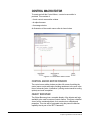
APPENDIX A CONTROL MACRO EDITOR . . . . . . A-1
Introduction to Control Macro Editor . . . . . . . . . . . . . . . . . . . . . . . . .A-1
Control macro Language . . . . . . . . . . . . . . . . . . . . . . . . . . . . . . . . .A-2
Example control Macro . . . . . . . . . . . . . . . . . . . . . . . . . . . . . . . . .A-3
Control Macro Editor. . . . . . . . . . . . . . . . . . . . . . . . . . . . . . . . . . . . .A-4
Control macro Editor Window . . . . . . . . . . . . . . . . . . . . . . . . . . . .A-4
Object Browser . . . . . . . . . . . . . . . . . . . . . . . . . . . . . . . . . . . . . . .A-4
Message Window . . . . . . . . . . . . . . . . . . . . . . . . . . . . . . . . . . . . .A-5
Running Control Macros . . . . . . . . . . . . . . . . . . . . . . . . . . . . . . . .A-5
Starting the Control Macro Editor . . . . . . . . . . . . . . . . . . . . . . . . . . .A-5
Configuration Entities . . . . . . . . . . . . . . . . . . . . . . . . . . . . . . . . . . . .A-8
Available Modules. . . . . . . . . . . . . . . . . . . . . . . . . . . . . . . . . . . . . .A-10
ClearCom . . . . . . . . . . . . . . . . . . . . . . . . . . . . . . . . . . . . . . . . . .A-10
Entities . . . . . . . . . . . . . . . . . . . . . . . . . . . . . . . . . . . . . . . . . . .A-10
Attachment Objects . . . . . . . . . . . . . . . . . . . . . . . . . . . . . . .A-11
Control Objects . . . . . . . . . . . . . . . . . . . . . . . . . . . . . . . . . .A-12
Entity Objects. . . . . . . . . . . . . . . . . . . . . . . . . . . . . . . . . . . .A-13
Port Objects . . . . . . . . . . . . . . . . . . . . . . . . . . . . . . . . . . . . .A-14
Scriptlibrary . . . . . . . . . . . . . . . . . . . . . . . . . . . . . . . . . . . . . . .A-15
Condition . . . . . . . . . . . . . . . . . . . . . . . . . . . . . . . . . . . . . . .A-16
Control Actions . . . . . . . . . . . . . . . . . . . . . . . . . . . . . . . . . .A-16
Control Attachments . . . . . . . . . . . . . . . . . . . . . . . . . . . . . .A-17
Control Latch . . . . . . . . . . . . . . . . . . . . . . . . . . . . . . . . . . . .A-18
Control Macro . . . . . . . . . . . . . . . . . . . . . . . . . . . . . . . . . . .A-19
Crosspoint Control . . . . . . . . . . . . . . . . . . . . . . . . . . . . . . . .A-20
Current. . . . . . . . . . . . . . . . . . . . . . . . . . . . . . . . . . . . . . . . .A-21
Shared. . . . . . . . . . . . . . . . . . . . . . . . . . . . . . . . . . . . . . . . . . . . .A-22
Creating a New Project. . . . . . . . . . . . . . . . . . . . . . . . . . . . . . . . . .A-23
Elements of a Control Macro. . . . . . . . . . . . . . . . . . . . . . . . . . . .A-27
Macro Reference . . . . . . . . . . . . . . . . . . . . . . . . . . . . . . . . . . . . . .A-29
AttachmentObject Macros . . . . . . . . . . . . . . . . . . . . . . . . . . . . . .A-29
Control Object Macros . . . . . . . . . . . . . . . . . . . . . . . . . . . . . . . .A-33
Port Object Macros . . . . . . . . . . . . . . . . . . . . . . . . . . . . . . . . . . .A-36
Condition Macros . . . . . . . . . . . . . . . . . . . . . . . . . . . . . . . . . . . .A-40
Control Actions Macro. . . . . . . . . . . . . . . . . . . . . . . . . . . . . . . . .A-41
Control Attachment Macros. . . . . . . . . . . . . . . . . . . . . . . . . . . . .A-47
Control Latch Macros . . . . . . . . . . . . . . . . . . . . . . . . . . . . . . . . .A-48
ii
Clear-Com
Eclipse Logic Maestro Instruction Manual
Control Macros . . . . . . . . . . . . . . . . . . . . . . . . . . . . . . . . . . . . . .A-51
Crosspoint Control . . . . . . . . . . . . . . . . . . . . . . . . . . . . . . . . . . .A-55
Current Macros . . . . . . . . . . . . . . . . . . . . . . . . . . . . . . . . . . . . . .A-56
Logging Macros. . . . . . . . . . . . . . . . . . . . . . . . . . . . . . . . . . . . . .A-58
APPENDIX B EXAMPLE CONTROL MACROS . . . B-1
Activate Specific Key LED. . . . . . . . . . . . . . . . . . . . . . . . . . . . . . .B-1
Activate LED on all Keys to Destination . . . . . . . . . . . . . . . . . . . .B-2
Trigger Action when both A and B are Set . . . . . . . . . . . . . . . . . .B-3
Trigger Action when all of A and B and C are Set. . . . . . . . . . . . .B-4
Cut Talk to Studio . . . . . . . . . . . . . . . . . . . . . . . . . . . . . . . . . . . . .B-5
Cut Talk to Studio, Excluding Some Panels . . . . . . . . . . . . . . . . .B-6
Trigger Action when both A is Set and a Crosspoint is made . . . .B-7
Trigger Action when Group 1 Member Talks to Group 2 Member.B-8
Headset-Select On . . . . . . . . . . . . . . . . . . . . . . . . . . . . . . . . . . . .B-9
Headset-Select On Always . . . . . . . . . . . . . . . . . . . . . . . . . . . . .B-10
Loudspeaker-Cut On. . . . . . . . . . . . . . . . . . . . . . . . . . . . . . . . . . B-11
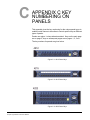
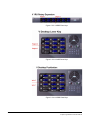
APPENDIX C KEY NUMBERING ON PANELS . . . C-1
GLOSSARY . . . . . . . . . . . . . . . . . . . . . . . . . . . . . . . D-1
Eclipse Manuals . . . . . . . . . . . . . . . . . . . . . . . . . . . . . . . . . . . . . . . D-5
Software Manuals . . . . . . . . . . . . . . . . . . . . . . . . . . . . . . . . . . . . D-5
Hardware Manuals . . . . . . . . . . . . . . . . . . . . . . . . . . . . . . . . . . . D-5
LIMITED WARRANTY . . . . . . . . . . . . . . . . . . . . . . . W-I
TECHNICAL SUPPORT & REPAIR POLICY. . . . . W-V
TECHNICAL SUPPORT POLICY . . . . . . . . . . . . . . . . . . . . . . . . . . W-v
RETURN MATERIAL AUTHORIZATION POLICY . . . . . . . . . . . . . W-vi
REPAIR POLICY . . . . . . . . . . . . . . . . . . . . . . . . . . . . . . . . . . . . . W-viii
Clear-Com
Eclipse Logic Maestro Instruction Manual
iii
iv
Clear-Com
Eclipse Logic Maestro Instruction Manual
FIGURES
Figure 1-1 ECS Configuration Menu................................................ 1-2
Figure 1-2 Logic Maestro Control Sequence List ............................ 1-3
Figure 1-3 Control Sequence Display.............................................. 1-4
Figure 1-4 Control Sequence Properties ......................................... 1-4
Figure 1-5 New Control Sequence Dialog ....................................... 1-6
Figure 1-6 License Key Request ..................................................... 1-7
Figure 1-7 Control Sequence Delete Confirmation.......................... 1-7
Figure 1-8 Control Sequence Import Dialogue ................................ 1-8
Figure 1-9 Control Sequence Export Dialogue ................................ 1-8
Figure 1-10 Project Clone Dialogue................................................. 1-9
Figure 1-11 Logic Maestro Interface.............................................. 1-10
Figure 1-12 List of Configuration Elements ................................... 1-11
Figure 1-13 Example Control Sequence........................................ 1-12
Figure 1-14 Control Input Module .................................................. 1-13
Figure 1-15 Control Input Menu..................................................... 1-13
Figure 1-16 Adding a Control to the Control Input List .................. 1-13
Figure 1-17 Added Further Controls to a Control Input ................. 1-14
Figure 1-18 Control List Editing ..................................................... 1-14
Figure 1-19 Control Input Description............................................ 1-15
Figure 1-20 Copying a Control Input.............................................. 1-15
Figure 1-21 Pasting a Control Input............................................... 1-15
Figure 1-22 Control Output Module ............................................... 1-16
Figure 1-23 Control Output Menu .................................................. 1-16
Figure 1-24 Adding a Control to the Control Output List................ 1-16
Figure 1-25 Adding Further Controls to a Control Output.............. 1-17
Figure 1-26 Control List Editing ..................................................... 1-17
Figure 1-27 Control Output Description ......................................... 1-17
Figure 1-28 Copying a Control Output........................................... 1-18
Figure 1-29 Pasting a Control Output ............................................ 1-18
Figure 1-30 Examples of Controls ................................................. 1-19
Figure 1-31 Default Control Panel Module .................................... 1-20
Figure 1-32 Panel Control Options ................................................ 1-20
Figure 1-33 Key Signalization Options .......................................... 1-21
Figure 1-34 Panel Override Options for Key Signalization ............ 1-21
Figure 1-35 Panel Override IF Active Example ............................. 1-22
Figure 1-36 Permanent Override of Local Example ...................... 1-22
Figure 1-37 Advanced Override of Local Example ........................ 1-23
Figure 1-38 Crosspoint Trigger...................................................... 1-23
Figure 1-39 Crosspoint Trigger Type Menu................................... 1-24
Figure 1-40 Menu Selected ........................................................... 1-24
Figure 1-41 New Item Added......................................................... 1-24
Figure 1-42 Adding All Ports or Panels to Crosspoint Trigger ....... 1-25
Figure 1-43 Crosspoint Trigger Source Options ............................ 1-25
Figure 1-44 Destination Menu Selected ........................................ 1-26
Figure 1-45 New Item Added......................................................... 1-26
Figure 1-46 Adding All Ports or Panels to Crosspoint Trigger ....... 1-26
Clear-Com
Eclipse Logic Maestro Instruction Manual
i
Figure 1-47 Crosspoint Trigger Source Options ............................ 1-27
Figure 1-48 Pin to Source List Destination Option......................... 1-27
Figure 1-49 Delete Pin to Source List Option ................................ 1-28
Figure 1-50 Cross Points Options.................................................. 1-28
Figure 1-51 All Possible Crosspoints Set as Trigger ..................... 1-28
Figure 1-52 Mix-Minus Crosspoints ............................................... 1-29
Figure 1-53 Diagonal Crosspoints ................................................. 1-29
Figure 1-54 Crosspoint Trigger for Crosspoint Action ................... 1-30
Figure 1-55 Crosspoints Triggering Control Outputs ..................... 1-31
Figure 1-56 Crosspoint Triggering Many Actions .......................... 1-32
Figure 1-57 Many to Many Action with Buffer................................ 1-33
Figure 1-58 Crosspoint Action ....................................................... 1-33
Figure 1-59 Crosspoint Actions List............................................... 1-34
Figure 1-60 Crosspoint Type List................................................... 1-34
Figure 1-61 Crosspoint Action Priority ........................................... 1-35
Figure 1-62 Crosspoint Action Source List .................................... 1-35
Figure 1-63 Adding a New Source................................................. 1-36
Figure 1-64 Adding All Ports or Panels to Crosspoint Action Source ....
1-36
Figure 1-65 Crosspoint Action Source Options ............................. 1-36
Figure 1-66 Destination Menu Selected ........................................ 1-37
Figure 1-67 New Destination Item Added...................................... 1-37
Figure 1-68 Adding All Ports or Panels to Crosspoint Action ........ 1-38
Figure 1-69 Crosspoint Action Destination Options....................... 1-38
Figure 1-70 Pin to Source List Destination Option......................... 1-39
Figure 1-71 Delete Pin to Source List Option ................................ 1-39
Figure 1-72 Crosspoint Pin to Source Options .............................. 1-39
Figure 1-73 All Possible Crosspoints Set as Action....................... 1-40
Figure 1-74 Mix-Minus Crosspoints ............................................... 1-40
Figure 1-75 Loopback Crosspoints................................................ 1-41
Figure 1-76 Inserting a Logic Element into a Connection.............. 1-42
Figure 1-77 Menu Options for AND Logic Element ....................... 1-43
Figure 1-78 Menu Options for NAND Logic Element..................... 1-44
Figure 1-79 Menu Options for OR Logic Element.......................... 1-45
Figure 1-80 Menu Options for NOR Logic Element ....................... 1-46
Figure 1-81 Menu Options for BUFFER Logic Element................. 1-47
Figure 1-82 Menu Options for NOT Logic Element ....................... 1-48
Figure 1-83 Menu Options for LATCH Logic Element ................... 1-49
Figure 1-84 Latch Sequence Using Toggle ................................... 1-50
Figure 1-85 Latch Example using All Inputs .................................. 1-51
Figure 1-86 Menu Options for Enable Logic Element.................... 1-51
Figure 1-87 Menu Options for Disable Logic Element ................... 1-52
Figure 1-88 AND, NAND and BUFFER Logic Elements................ 1-53
Figure A-1 Control Macro Editor Screen.......................................... A-4
Figure A-2 Control Macro Editor from Logic Maestro ...................... A-5
Figure A-3 License Key Request ..................................................... A-6
Figure A-4 Initial Macro Control Macro Editor Display..................... A-7
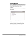
Figure A-5 Configuration Selection.................................................. A-8
Figure A-6 Configuration Entities List .............................................. A-9
Figure A-7 ClearCom Module Libraries ......................................... A-10
ii
Clear-Com
Eclipse Logic Maestro Instruction Manual
Figure A-8 Entity Libraries ............................................................. A-11
Figure A-9 Attachment Objects Library.......................................... A-11
Figure A-10 Example of Attachment Object Properties ................. A-12
Figure A-11 Control Objects List.................................................... A-13
Figure A-12 Entity Object List ........................................................ A-14
Figure A-13 Port Object List .......................................................... A-15
Figure A-14 Script Library Categories ........................................... A-16
Figure A-15 Conditions List ........................................................... A-16
Figure A-16 Control Actions List .................................................... A-17
Figure A-17 Control Attachment List.............................................. A-18
Figure A-18 Control Latch Actions List .......................................... A-19
Figure A-19 Control Macro List...................................................... A-20
Figure A-20 Crosspoint Controls ................................................... A-21
Figure A-21 System Current .......................................................... A-21
Figure A-22 Shared Object List ..................................................... A-22
Figure A-23 New Project Screen ................................................... A-23
Figure A-24 Start New Control Macro............................................ A-24
Figure A-25 Inital New Control Macro............................................ A-25
Figure A-26 Control Macro with Port Commands .......................... A-26
Figure A-27 Macro Parameter Entry Window ................................ A-27
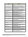
Figure C-1 4212 Panel Keys........................................................... C-1
Figure C-2 4215 Panel Keys........................................................... C-1
Figure C-3 4222 Panel Keys........................................................... C-1
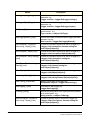
Figure C-4 4224 Panel Keys........................................................... C-2
Figure C-5 4226 Panel Keys........................................................... C-2
Figure C-6 i-Station Panel Keys ..................................................... C-2
Figure C-7 ICS-1008 Panel Keys ................................................... C-2
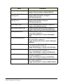
Figure C-8 ICS-1016 Panel Keys ................................................... C-3
Figure C-9 ICS-102 Panel Keys ..................................................... C-3
Figure C-10 ICS-2003 Panel Keys ................................................. C-3
Figure C-11 ICS-52 Panel keys ...................................................... C-3
Figure C-12 ICS-62 Panel Keys ..................................................... C-4
Figure C-13 ICS-92 Panel Keys ..................................................... C-4
Figure C-14 V12LD Panel Keys...................................................... C-4
Figure C-15 V12PD Panel Keys ..................................................... C-4
Figure C-16 V12RD Panel Keys ..................................................... C-4
Figure C-17 V24LD Panel Keys...................................................... C-5
Figure C-18 V24PD Panel Keys ..................................................... C-5
Figure C-19 V24RD Panel keys...................................................... C-5
Figure C-20 V12LDE Panel Keys ................................................... C-5
Figure C-21 V12PDE Panel keys ................................................... C-5
Figure C-22 V12RDE Panel keys ................................................... C-6
Figure C-23 V12LDD Panel Keys ................................................... C-6
Figure C-24 V12PDD Panel Keys................................................... C-6
Figure C-25 V12RDD Panel Keys .................................................. C-7
Figure C-26 Beltpack Keys ............................................................. C-7
Clear-Com
Eclipse Logic Maestro Instruction Manual
iii
iv
Clear-Com
Eclipse Logic Maestro Instruction Manual
1
Logic Maestro is a
graphical tool to
generate control macro
scripts.
LOGIC MAESTRO
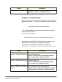
INTRODUCTION
The Logic Maestro facility in ECS is a separately licensable option
which allows control sequences to be generated using the Logic
Maestro visual programming interface. The facility to create and edit
control sequence scripts directly is also available in the option via the
Control Macro editor (see appendices in section 2 A and B).
Control sequences allow the configuration that controls matrix
operation to be directly modified to carry out specific actions when
triggered. Each control sequence contains a series of commands with
each defined command representing an action carried out on an object
in the configuration. An object may be a port, an input or output device
or label.
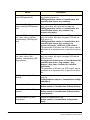
The main use of control sequences is to select controls which have
already been configured using ECS and modify the actions that they
trigger when activated.
Each defined control sequence is named and can have multiple inputs
and outputs and combination logic. These sequences take the form of
actions to be associated with inputs, and the Logic Maestro editor will
assist the author by providing an overview of available actions and the
parameters each requires in order to perform the required function.
Logic elements are available (e.g. AND, NAND, OR, NOR), with
tooltips supplied by the Logic Maestro editor.
It is possible that more than one control sequence in a configuration
generated using Logic Maestro or the Control Macros editor may target
the same action such as loudspeaker cut on a panel. This may result
in one control overriding the effect of another control. For example, if
two controls request loudspeaker cut on a panel, if one of the controls
cancels the action it will be cancelled for both regardless of whether
the other control has cancelled the action. Care should be taken to
ensure that multiple controls do not target the same action to avoid
unexpected results when multiple control sequences operate on the
same action.
Clear-Com
Eclipse Logic Maestro Instruction Manual
1-1
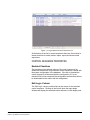
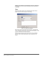
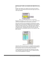
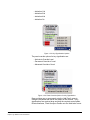
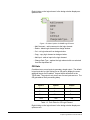
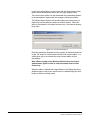
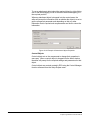
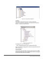
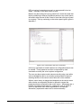
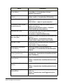
OPERATION
To start Logic Maestro click on the ‘Logic Maestro’ link in the
Configuration menu.
Figure 1-1: ECS Configuration Menu
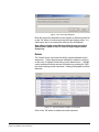
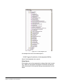
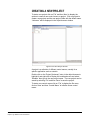
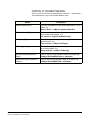
The Logic Maestro design window will be opened displaying the initial
command window with a list of known logic design. The logic design
properties are displayed in seven columns.
1-2
Clear-Com
Eclipse Logic Maestro Instruction Manual
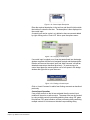
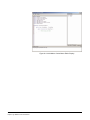
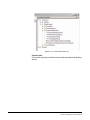
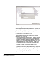
Figure 1-2: Logic Maestro Control Sequence List
At the bottom of the list of control sequences there are five buttons to
access functions to create, delete, import, export and clone control
sequences.
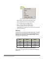
CONTROL SEQUENCE PROPERTIES
Enabled Checkbox
The checkbox in the leftmost column of the control sequence list
determines whether the Logic Maestro control sequence is saved with
the system configuration in the database. If the box is checked the
control sequence will be saved with the configuration; if it is not
checked it will not be saved with the configuration and therefore will not
be downloaded to the matrix with the configuration.
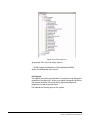
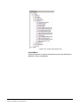
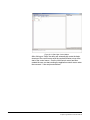
Edit Logic Column
The ‘Edit Logic’ column contains links to the source for the selected
control sequence. Clicking on the link will open the logic design
window and display the selected control sequence in the design pane.
Clear-Com
Eclipse Logic Maestro Instruction Manual
1-3
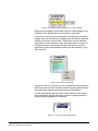
Figure 1-3: Control Sequence Display
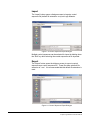
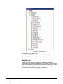
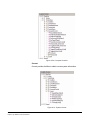
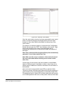
Edit Properties Column
The ‘Edit Properties’ column contains links to the information for the
selected control sequence. Clicking on this link allows the control
sequence name, project name, author and description to be modified.
Figure 1-4: Control Sequence Properties
Name
The ‘Name’ column lists the names of the known control sequence
designs. The control sequence design name is edited by selecting the
‘Edit Properties’ link for the required control sequence design.
1-4
Clear-Com
Eclipse Logic Maestro Instruction Manual
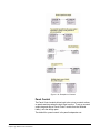
Project
The ‘Project’ column lists the project names associated with the control
sequences. These project names are optional and are simply to assist
in grouping control sequences together.
Author
The ‘Author’ column lists the names of authors associated with the
control sequences. These author names are optional and are simply
for information.
Description
The ‘Description’ column lists the descriptions associated with the
control sequences. These descriptions are optional and are simply for
information.
Clear-Com
Eclipse Logic Maestro Instruction Manual
1-5
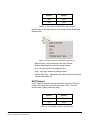
FUNCTION BUTTONS
The buttons at the bottom of the logic design window allow control
sequences to be created, deleted, imported from files, exported to files
and cloned.
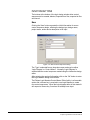
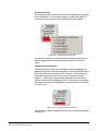
New
Clicking the ‘New’ button requests the initial information for a new
control sequence design, allowing the design type, design name,
project name, author and a description to be input.
Figure 1-5: New Control Sequence Dialog
The ‘Type’ is selected from a drop-down menu and may be either
‘Logic Diagram’ or ‘Control Macro’. Normally ‘Logic Diagram’ is
selected and the control sequence created using the interactive design
editor.
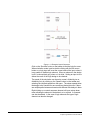
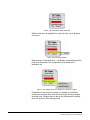
After entering the required information click on the ‘OK’ button to enter
the Logic Maestro design environment.
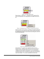
The Eclipse Logic Maestro/Control Macro Editor facility is a licensable
option and a license key is required to use Logic Maestro to create
new control sequences. When the logic diagram editor is first started it
will request a license key if one has not already been input.
1-6
Clear-Com
Eclipse Logic Maestro Instruction Manual
Figure 1-6: License Key Request
Enter the license key obtained from the supplier or distributor and click
on the ‘OK’ button to continue and start the logic diagram editor. If a
valid license key is not entered the editor will exit immediately.
Note: When running under Windows Vista the user must have
administrator rights in order to enter the logic diagram editor
license key.
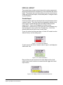
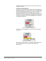
Delete
The ‘Delete’ button is provides the facility to delete selected control
sequences. Control sequences are selected for deletion by clicking
on the entry to highlight it and clicking on the delete button. Multiple
control sequences can be selected for deletion by pressing the ‘Shift’
key while selecting control sequences. A dialog is displayed to confirm
the action.
Figure 1-7: Control Sequence Delete Confirmation
Click on the ‘OK’ button to delete the control sequence.
Clear-Com
Eclipse Logic Maestro Instruction Manual
1-7
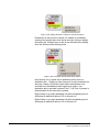
Import
The ‘Import’ button opens a dialogue screen to import a control
sequence file (default file extension .ccm) into Logic Maestro.
Figure 1-8: Control Sequence Import Dialogue
Multiple control sequences can be selected for import by holding down
the ’Shift’ key while selecting the control sequences to be imported.
Export
The ‘Export’ button opens the dialogue screen to export a control
sequence as a control sequence file. These files have a default file
extension of ‘.ccm’. It is recommended that this default file extension is
used.
Figure 1-9: Control Sequence Export Dialogue
1-8
Clear-Com
Eclipse Logic Maestro Instruction Manual
Multiple control sequences can be selected for export to a single file by
holding down the ’Shift’ key while selecting the control sequences to
be exported.
Clone
Select the control sequence to be cloned and click on the ‘Clone’
button to open the control sequence clone dialog.
Figure 1-10: Project Clone Dialogue
Enter a new name for the cloned control sequence, and optionally
enter or change the project name, author name and description. Click
on ‘OK’ to create the new control sequence.
Multiple control sequences can be selected for cloning by holding
down the ’Shift’ key while selecting the control sequences to be
cloned.
Clear-Com
Eclipse Logic Maestro Instruction Manual
1-9
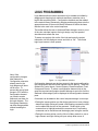
LOGIC PROGRAMMING
Logic Maestro allows control sequences to be created and edited by
dragging and dropping logic elements and library modules onto a
layout and connecting them. Configuration elements are then added
to the module library elements by dragging and dropping them onto the
appropriate areas of the module library elements to define the items
that are to be used in the control sequence.
The toolbar allows the user to Undo and Redo changes, zoom in or out
of the view, simulate inputs to the logic design, vary the speed of
simulation and refresh the view.
To start a new project click on the ‘New’ tab and enter the project
information into the dialogue screen and click on ‘OK’. The control
logic layout screen is then opened.
Note: If the
configuration changes
label names the
Configuration elements
already used in the
logic diagram will show
red for error. To
prevent this set up fixed
groups in ECS with the
configuration element
you need to remain
static and use these for
the logic diagram. The
fixed group member(s)
can then change names
without breaking the
logic.
Figure 1-11: Logic Maestro Interface
Configuration elements are devices present in the target configuration
(the configuration that the control sequence will be part of). These are
divided into Control Inputs, Control Outputs, Directs/Interfaces, Fixed
Groups and Panels. To select a configuration element click on the
group the required configuration element belongs to and a list of all the
elements in that category will be displayed in the configuration element
pane.
Comments can be added to the control sequence design in two ways:
• Placing the mouse pointer over the design pane but not over a design
element and right clicking will create a free-floating comment box that
can be edited with the text of the comment. Double click on the
comment box to highlight and edit the comment text. Free floating
comments can be moved around the design panel using the mouse.
• Placing the mouse pointer over the title of a library module or over a
logic element and right clicking will open a drop down menu of
1-10
Clear-Com
Eclipse Logic Maestro Instruction Manual
options. Selecting ‘Add Comment’ will create a comment attached to
the module or logic element. Double click on the comment box to
highlight and edit the comment text. Attached comments can be
moved around the design panel using the mouse but will always
remain connected to the target item.
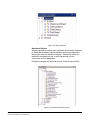
Figure 1-12: List of Configuration Elements
In the case of devices with talk and listen labels both labels are
displayed in the list in the format ‘talk label’,’listen label’. Devices that
do not have talk and listen labels are identified by name.
Logic elements can be dragged into the design pane and placed for
connection to other elements.
To connect a control input to a logic element simply place the mouse
pointer over the connection point on the control input, left click and
hold, and drag the connection to the required connection point on the
logic element and release the mouse button. The same process is
used to connect the output from a logic element to a control output.
Clear-Com
Eclipse Logic Maestro Instruction Manual
1-11
Figure 1-13: Example Control Sequence
Click on the ‘Simulate’ button on the toolbar to test the logic for errors.
When simulation mode is active double clicking with the left mouse
button on a logic input will invert the current state of the input unless it
is an enable or disable logic element. When an element in the design
is off it is colored dark grey, when on it is white. Setting an input to true
allows the result of the logic design to be checked.
The speed of the simulation can be set to normal, divided by ten or
divided by forty by clicking on the ‘Speed’ button on the toolbar and
selecting the required speed from the menu. The slower speeds allow
the design to be checked for race conditions that might occur if there
are multiple paths between elements with different time delays in them.
Right clicking on a control sequence element will open a drop down
menu allowing the element to be deleted, cut or copied. A comment
can also be added. In the case of logic elements the type of logic
element can also be changed.
1-12
Clear-Com
Eclipse Logic Maestro Instruction Manual
MODULE LIBRARY
The module library provides control items which can be programmed
with physical devices such as panel keys, direct interfaces and control
labels. The physical items are then acted upon by the control items to
create logic inputs and outputs, create audio paths or change the state
of panel hardware.
Control Input
Control inputs are used to provide inputs to the control sequence when
a control is active. The control inputs are triggered by controls set up
in ECS by the Control Manager and are usually General Purpose
Inputs (GPIs). These may be attached to devices such as
footswitches. Controls set up in ECS using the Control Manager may
also be assigned to keys under Panel Programming. In this case
activating the panel key will act as a control input.
To set up a control input drag and drop a ‘Control I/P’ module from the
‘Module Library’ onto the design pane.
Figure 1-14: Control Input Module
To add a control click on the ‘Controls’ menu to open it and display the
‘Add control’ item.
Figure 1-15: Control Input Menu
Drag and drop an item from the list of control labels onto the ‘Add
control’ item to add it to the list of controls that will trigger the Control
Input function.
Figure 1-16: Adding a Control to the Control Input List
Clear-Com
Eclipse Logic Maestro Instruction Manual
1-13
Alternatively control labels can be dragged and dropped directly onto
the unexpanded ‘Controls’ menu and they will be added to the controls
list.
Multiple control labels can be added to the control input module to
create a list of control labels that will activate the logic input from the
control input module.
Figure 1-17: Added Further Controls to a Control Input
Dragging and dropping a control label on top of a label already in the
controls list will replace that item with the new control label.
Items on the control list can be selected by left clicking on the items;
multiple items can be selected by holding down the shift key while left
clicking on the items to select them. Right clicking on the selected
control item or items will open a menu giving the options to Copy, Cut
or Delete the items. Alternatively the entire list can be copied by
right-clicking on the unexpanded controls menu and selecting ‘’Copy
this Control list’.
Figure 1-18: Control List Editing
If items from the list of controls are cut or copied they may be pasted
directly into the control list of another control input by right clicking on
the unexpanded controls menu and selecting ‘Add selection’.
To enter a description into the control input double left click on the
word ‘Description’ and the description text box is displayed with the
current content highlighted for overtyping.
1-14
Clear-Com
Eclipse Logic Maestro Instruction Manual
Figure 1-19: Control Input Description
Enter the required description in the text box and then left click outside
the text box to close the text box. The description is then displayed on
the control input.
A control input can be copied, cut, deleted or have a comment added
by right clicking on the ‘Control I/P’ title to open the options menu.
Figure 1-20: Copying a Control Input
If a control input is copied or cut it can be pasted back into the design
window complete with the list of assigned controls and the description.
Deletion will remove the control input and ‘Add Comment’ will add an
attached comment as described previously. To paste a copy of a
control input place the mouse pointer over a free space in the design
window and right click to open the menu.
Figure 1-21: Pasting a Control Input
Click on ‘Insert Comment’ to add a free-floating comment as described
previously.
Control Input Operation
If any of the controls on the list are activated then the control input
module will be set to an active output. The same effect can be created
by using multiple control inputs and combining them using ‘OR’ gates
but whereas ‘OR’ gates introduce a 25ms processing delay combining
multiple controls in a list does not introduce a processing delay.
Clear-Com
Eclipse Logic Maestro Instruction Manual
1-15
Control Output
Control outputs are used to activate outputs when the input state is
true. To set up a control output drag and drop a ‘Control O/P’ module
from the ‘Module Library’ onto the design pane.
Figure 1-22: Control Output Module
To add a control click on the ‘Controls’ menu to open it and display the
‘Add control’ item.
Figure 1-23: Control Output Menu
Drag and drop an item from the list of control labels onto the ‘Add
control’ item to add it to the list of controls that will be triggered by the
Control Output. The output control labels are set up in ECS by the
Control Manager and are usually General Purpose Outputs (GPOs).
These may be attaches to external devices such as relays to control
devices such as lights or door switches.
Figure 1-24: Adding a Control to the Control Output List
Alternatively control labels can be dragged and dropped directly onto
the unexpanded ‘Controls’ menu and they will be added to the controls
list.
Multiple control labels can be added to the control output module to
create a list of control labels that will be activated by the Control Output
module when it receives an active input.
1-16
Clear-Com
Eclipse Logic Maestro Instruction Manual
Figure 1-25: Adding Further Controls to a Control Output
Dragging and dropping a control label on top of a label already in the
controls list will replace that item with the new control label.
Items on the control list can be selected by left clicking on the items;
multiple items can be selected by holding down the shift key while left
clicking on the items to select them. Right clicking on the selected
control item or items will open a menu giving the options to Copy, Cut
or Delete the items. Alternatively the entire list can be copied by
right-clicking on the unexpanded controls menu and selecting ‘’Copy
this Control list’.
Figure 1-26: Control List Editing
If items from the list of controls are cut or copied they may be pasted
directly into the control list of another control output by right clicking on
the unexpanded controls menu and selecting ‘Add selection’.
To enter a description into the control output double left click on the
word ;Description’ and the description text box is displayed with the
current content highlighted for overtyping.
Figure 1-27: Control Output Description
Clear-Com
Eclipse Logic Maestro Instruction Manual
1-17
Enter the required description in the text box and then left click outside
the text box to close the text box. The description is then displayed on
the control output.
A control output can be copied, cut, deleted or have a comment added
by right clicking on the ‘Control O/P’ title to open the options menu.
Figure 1-28: Copying a Control Output
If a control output is copied or cut it can be pasted back into the design
window complete with the list of assigned controls and the description.
Deletion will remove the control output and ‘Add Comment’ will add an
attached comment as described previously. To paste a copy of a
control output place the mouse pointer over a free space in the design
window and right click to open the menu.
Figure 1-29: Pasting a Control Output
Click on ‘Insert Comment’ to add a free-floating comment as described
previously.
Some examples of the use of input and output controls are shown in
Figure 1-30 below.
1-18
Clear-Com
Eclipse Logic Maestro Instruction Manual
Figure 1-30: Examples of Controls
Panel Control
The Panel Control module allows logic to be set up to control actions
on panels and keys when the logic input is active. To set up a control
output drag and drop a ‘Panel Control’ module from the ‘Module
Library’ onto the design pane.
The default for a panel control is for panel loudspeaker cut.
Clear-Com
Eclipse Logic Maestro Instruction Manual
1-19
Figure 1-31: Default Control Panel Module
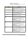
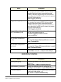
The panel control module offers the following options:
• Cut the panel loudspeaker
• Dim the panel loudspeaker
• Select the panel headset
• Mute the panel microphone
• Set the key signalization to red when active
• Set the key signalization to green when active
• Set the key signalization to amber when active
To select a different option open the action menu (‘Loudspeaker Cut’)
and right click on the current option to display the options list.
Figure 1-32: Panel Control Options
Select the panel control option required from the list by left clicking on
it. The list will be closed and the panel control module display will be
updated according to the option selected.
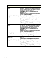
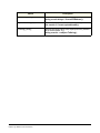
If a key signalization is selected red, green, amber) the key indication
on the label can be set to one of the options:
• Indication Off
1-20
Clear-Com
Eclipse Logic Maestro Instruction Manual
• Indication 1Hz
• Indication 2Hz
• Indication 4Hz
• Indication On
Figure 1-33: Key Signalization Options
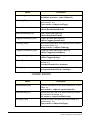
The panel override options for key signalization are:
• Activate to Override Local
• Permanent Override of Local
• Advanced Override of Local
Figure 1-34: Panel Override Options for Key Signalization
Drag and drop one or more panels onto the ‘Add Panel’ menu to
configure the panels that will be the subject of the controls. If key
signalizations are required drag and drop the required control labels,
Directs/Interfaces, Fixed Groups or Panels onto the ‘Add Label’ menu.
Clear-Com
Eclipse Logic Maestro Instruction Manual
1-21
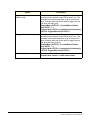
If a panel loudspeaker, headset or microphone action is selected the
‘Labels’ menu is not available. It is only available when a key
signalization panel action is selected.
If loudspeaker cut, loudspeaker dim, select panel headset or panel
microphone mute are set as the action the options menu for these
actions are:
• Activate to Override Local. Overrides the current setting of the
device if it is currently active. If it is not active the control has no
effect.
Figure 1-35: Panel Override IF Active Example
• Permanent Override of Local. Always overrides the current
setting of the device regardless of whether it is active or not.
Figure 1-36: Permanent Override of Local Example
• Advanced Override of Local. In this case there are two control
inputs to the panel. The first control input must be active for the
second control input to take over the panel function.
1-22
Clear-Com
Eclipse Logic Maestro Instruction Manual
Figure 1-37: Advanced Override of Local Example
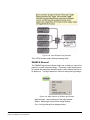
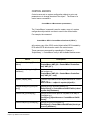
Crosspoint Trigger
Crosspoint triggers allow audio crosspoints to be used to generate a
control output to another action which may be a control output or a
crosspoint action. Crosspoint triggers are configured with sources and
destinations selected from the lists of fixed groups and panels that
define the crosspoints.
To set a crosspoint trigger drag and drop an ‘Xpt Trigger’ from the
‘Module Library’ pane onto the design pane.
Figure 1-38: Crosspoint Trigger
Trigger Crosspoint Type
Open the crosspoint type menu and right click on the current type to
display the menu of trigger types.
Clear-Com
Eclipse Logic Maestro Instruction Manual
1-23
Figure 1-39: Crosspoint Trigger Type Menu
The crosspoint trigger can be set to operate when either source to
destination crosspoints are made or bidirectional crosspoints are made
between any of the sources and destinations configured. Right click
on the menu item to select the crosspoint trigger type.
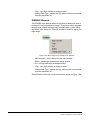
Crosspoint Trigger Sources
Crosspoint trigger sources can be added to the list by dragging and
dropping devices from the Direct/Interfaces, Fixed Groups and Panels
lists onto the source list whether or not it is open. If the source list is
opened then dropping a new source onto an existing source will
replace it. If there are no items already assigned to the source list
then the list name will be highlighted in red. If there are items already
assigned the list will not be highlighted but instead will be surrounded
by a green box.
Figure 1-40: Menu Selected
When the menu name is highlighted in yellow the item can be dropped
onto the menu.
Figure 1-41: New Item Added
1-24
Clear-Com
Eclipse Logic Maestro Instruction Manual
Right-clicking on ‘Add source...’ will display a menu allowing all the
ports or all the panels in the configuration to be added to the source
list.
Figure 1-42: Adding All Ports or Panels to Crosspoint Trigger
Sources in the list can be copied, cut, deleted or excluded by selecting
the required items from the list and right clicking to display the options
list. Multiple items on the list can be selected by holding down the Shift
key while selecting items.
Figure 1-43: Crosspoint Trigger Source Options
Items that are cut or copied can be pasted into other source or
destination lists. Deleting an item removes it from the list while the
‘Change to Excluded’ option allows a source to be excluded from
consideration when triggering an output. If a source is excluded it will
be displayed in red. If ‘All Ports’ is present in the source list this cannot
be excluded.
Crosspoint Trigger Destinations
Crosspoint trigger destinations can be added to the list by dragging
and dropping devices from the Direct/Interfaces, Fixed Groups and
Panels lists onto the destination list whether or not it is open. If the
destination list is opened then dropping a new destination onto an
existing destination will replace it. If there are no items already
assigned to the destination list then the list name will be highlighted in
red. If there are items already assigned the list will not be highlighted
but instead will be surrounded by a green box.
Clear-Com
Eclipse Logic Maestro Instruction Manual
1-25
Figure 1-44: Destination Menu Selected
When the list name is highlighted in yellow the item can be dropped
into the list.
Figure 1-45: New Item Added
Right-clicking on ‘Add destination...’ will display a menu allowing all the
ports or all the panels in the configuration to be added to the
destination list.
Figure 1-46: Adding All Ports or Panels to Crosspoint Trigger
Destinations in the list can be copied, cut, deleted or excluded by
selecting the required items from the list and right clicking to display
the options list. Multiple items on the list can be selected by holding
down the Shift key while selecting items.
1-26
Clear-Com
Eclipse Logic Maestro Instruction Manual
Figure 1-47: Crosspoint Trigger Source Options
Items that are cut or copied can be pasted into other source or
destination lists. Deleting an item removes it from the list while the
‘Change to Excluded’ option allows a destination to be excluded from
consideration when triggering an output. Any destination that has
been excluded is shown in red. If ‘All Ports’ is present in the
destination list this cannot be excluded. To re-include a destination
that has been excluded select it and right click to open the actions
menu and select ‘Change to Included’.
Figure 1-48: Pin to Source List Destination Option
Selecting the ‘Pin to Source List’ option replaces the ‘Destinations’
menu with ‘Dests => Sources’.
To reinstate the ‘Destinations’ menu right click on ‘Dests => Sources’
and select ‘Detach from Source List’.
Clear-Com
Eclipse Logic Maestro Instruction Manual
1-27
Figure 1-49: Delete Pin to Source List Option
The ‘Dests => Sources’ option replaces the destination list with a
matrix of crosspoints between all the sources in the source list. This is
shown by the crosspoint options menu being replaced by a new ‘All
Xpts’ menu. Right-clicking on the ‘All Xpts’ menu will display a list of
options allowing the crosspoint matrix to be modified.
Figure 1-50: Cross Points Options
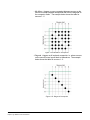
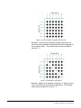
The crosspoint options for Pin to Source are:
• All Xpts - triggers on every crosspoint between sources in the
source list. The example below shows the table for sources 1 - 6.
Figure 1-51: All Possible Crosspoints Set as Trigger
1-28
Clear-Com
Eclipse Logic Maestro Instruction Manual
• Mix-Minus - triggers on every crosspoint between sources on the
source list except loopback crosspoints that form the diagonal on
the crosspoint matrix. The example below shows the table for
sources 1 - 6.
Figure 1-52: Mix-Minus Crosspoints
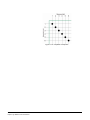
• Diagonal - triggers on all loopback crosspoints .i.e. where sources
on the source list are looped back to themselves. The example
below shows the table for sources 1 - 6.
Figure 1-53: Diagonal Crosspoints
Clear-Com
Eclipse Logic Maestro Instruction Manual
1-29
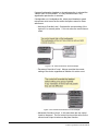
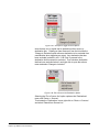
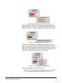
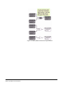
Crosspoint Trigger Examples
Examples of the use of crosspoint triggers and actions are shown
below.
Figure 1-54: Crosspoint Trigger for Crosspoint Action
In example Figure 1-54 when source ‘P1’ establishes an audio path to
destination ‘P3’ the crosspoint trigger will be activated to provide an
input to the crosspoint action. The crosspoint action will enable
crosspoints between the same source ‘P1’ and two other destinations
‘P6’ and ‘P7’ at priority 4.
The effect would be that whenever the panel operator ‘P1’ talks to ‘P3’
the audio will also be routed to ‘P6’ and ‘P7’.
Examples of crosspoint triggers used to trigger control outputs are
shown in Figure 1-55.
1-30
Clear-Com
Eclipse Logic Maestro Instruction Manual
Figure 1-55: Crosspoints Triggering Control Outputs
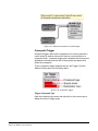
Crosspoints triggers can be used to enable other crosspoints so that a
single key could enable audio feeds from a number of sources to a
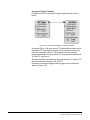
number of destinations as shown in Figure 1-56.
Clear-Com
Eclipse Logic Maestro Instruction Manual
1-31
Figure 1-56: Crosspoint Triggering Many Actions
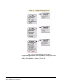
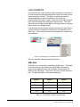
There is a constraint on the maximum number of possible actions by
crosspoint triggers and crosspoint actions imposed by system
resources. In general the number of possible triggers times the
number of possible actions should not exceed 4095. So if there are 16
possible triggers specified in an Xpt Trigger and 16 possible crosspoint
actions specified in a Xpt Action the number of actions would be:
16 triggers x 16 actions = 256 events
which would be acceptable. If the result of setting up a system of
crosspoint triggers and crosspoint actions created more than 4095
possible actions an error would be reported when the configuration
was downloaded.
In this case a buffer logic element should be placed between the
crosspoint trigger and crosspoint action. In this way the number of
actions the trigger crosspoint has to make is limited to the number of
trigger crosspoints, which only have to trigger the buffer. The buffer
will then act on the crosspoints in the crosspoint action. An example of
this is shown in Figure 1-57.
1-32
Clear-Com
Eclipse Logic Maestro Instruction Manual
Figure 1-57: Many to Many Action with Buffer
Crosspoint actions can also be triggered from control inputs either
directly or through other logic elements.
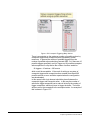
Crosspoint Action
Crosspoint actions allow crosspoint triggers or control inputs to act on
audio crosspoints in various ways depending on how the crosspoint
action is set up. Crosspoint actions are configured with sources and
destinations selected from the lists of fixed groups and panels that
define the crosspoints.
To set a crosspoint action drag and drop an ‘Xpt Action’ from the
‘Module Library’ pane onto the design pane.
Figure 1-58: Crosspoint Action
Action Type
The action type menu allows the type of action (enable, disable,
isolate) to be specified, together with the two of crosspoint to be acted
on (source to destination, bidirectional) and the crosspoint priority.
Open the action type menu and right click on the current action to
display the menu of crosspoint actions.
Clear-Com
Eclipse Logic Maestro Instruction Manual
1-33
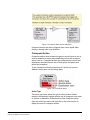
Figure 1-59: Crosspoint Actions List
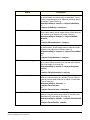
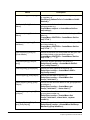
The available crosspoint actions are:
• Enable Action - enable all the crosspoints between the sources
and destinations that satisfy the crosspoint type and priority
criteria except where sources or destinations are marked as
excluded.
• Inhibit Action - inhibit all the crosspoints between the sources and
destinations that satisfy the crosspoint type and priority criteria
except where sources or destinations are marked as excluded.
• Isolate Action - isolate all the crosspoints between the sources
and destinations that satisfy the crosspoint type and priority
criteria except where sources or destinations are marked as
excluded. When isolate actions are applied to bidirectional
crosspoints it will only isolate the source to destination part of the
audio path, not the destination to source part.
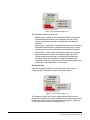
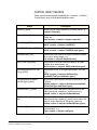
Crosspoint Type
Open the crosspoint action menu and right click on the current
crosspoint type to display the menu of crosspoint types.
Figure 1-60: Crosspoint Type List
The crosspoint action can be set to operate when either source to
destination crosspoints are made or bidirectional crosspoints are made
between any of the sources and destinations configured. Right click
on the menu item to select the crosspoint type.
1-34
Clear-Com
Eclipse Logic Maestro Instruction Manual
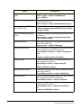
Crosspoint Priority
The crosspoint priority defines the priority at which the action is applied
to the crosspoints. For a crosspoint action to change the state of a
crosspoint it must be set to a priority higher than the crosspoint.
Figure 1-61: Crosspoint Action Priority
For example in order to override panel talk crosspoints at priority two
with a crosspoint action the action priority must be set to three or
higher.
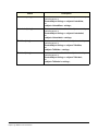
Crosspoint Action Sources
Crosspoint action sources can be added to the list by dragging and
dropping devices from the Direct/Interfaces, Fixed Groups and Panels
lists onto the source list whether or not it is open. If the source list is
opened then dropping a new source onto an existing source will
replace it. If there are no items already assigned to the source list
then the list name will be highlighted in red. If there are items already
assigned the list will not be highlighted but instead will be surrounded
by a green box.
Figure 1-62: Crosspoint Action Source List
When the menu name is highlighted in yellow the item can be dropped
onto the list.
Clear-Com
Eclipse Logic Maestro Instruction Manual
1-35
Figure 1-63: Adding a New Source
Right-clicking on ‘Add source...’ will display a menu allowing all the
ports or all the panels in the configuration to be added to the source
list.
Figure 1-64: Adding All Ports or Panels to Crosspoint Action Source
Sources in the list can be copied, cut, deleted or excluded by selecting
the required items from the list and right clicking to display the options
list. Multiple items on the list can be selected by holding down the Shift
key while selecting items.
Figure 1-65: Crosspoint Action Source Options
Items that are cut or copied can be pasted into other source or
destination lists. Deleting an item removes it from the list while the
‘Change to Excluded’ option allows a source to be excluded from
consideration when acting on crosspoints. Any source that has been
excluded is shown in red. If ‘All Ports’ is present in the source list this
cannot be excluded. To re-include a destination that has been
1-36
Clear-Com
Eclipse Logic Maestro Instruction Manual
excluded select it and right click to open the actions menu and select
‘Change to Included’.
Crosspoint Action Destinations
Crosspoint action destinations can be added to the list by dragging and
dropping devices from the Direct/Interfaces, Fixed Groups and Panels
lists onto the destination list whether or not it is open. If the destination
list is opened then dropping a new destination onto an existing
destination will replace it. If there are no items already assigned to the
destination list then the list name will be highlighted in red. If there are
items already assigned the list will not be highlighted but instead will be
surrounded by a green box.
Figure 1-66: Destination Menu Selected
When the list name is highlighted in yellow the item can be dropped
into the list.
Figure 1-67: New Destination Item Added
Right-clicking on ‘Add destination...’ will display a menu allowing all the
ports or all the panels in the configuration to be added to the
destination list.
Clear-Com
Eclipse Logic Maestro Instruction Manual
1-37
Figure 1-68: Adding All Ports or Panels to Crosspoint Action
Destinations in the list can be copied, cut, deleted or excluded by
selecting the required items from the list and right clicking to display
the options list. Multiple items on the list can be selected by holding
down the Shift key while selecting items.
Figure 1-69: Crosspoint Action Destination Options
Items that are cut or copied can be pasted into other source or
destination lists. Deleting an item removes it from the destination list
while the ‘Change to Excluded’ option allows a destination to be
excluded from consideration when triggering an output. Any
destination that is excluded is shown in red. If ‘All Ports’ is present in
the destination list this cannot be excluded.
Right clicking on an empty destination list without expanding the list
will display an additional option of ‘Pin to Source List’.
Right clicking on an empty destination list without expanding the list
will display an additional option of ‘Pin to Source List’.
1-38
Clear-Com
Eclipse Logic Maestro Instruction Manual
Figure 1-70: Pin to Source List Destination Option
Selecting the ‘Pin to Source List’ option replaces the ‘Destinations’
menu with ‘Dests => Sources’. To reinstate the ‘Destinations’ menu
right click on ‘Dests => Sources’ and select ‘Detach from Source List’.
Figure 1-71: Delete Pin to Source List Option
The ‘Dests => Sources’ option replaces the destination list with a
matrix of crosspoints between all the sources in the source list. This is
shown by the crosspoint options menu being replaced by a new ‘All
Xpts’ menu. Right-clicking on the ‘All Xpts’ menu will display a list of
options allowing the crosspoint matrix to be modified.
Figure 1-72: Crosspoint Pin to Source Options
The crosspoint options for Pin to Source are:
• All Xpts - acts on every crosspoint between sources in the source
list. The example below shows the table for sources 1 - 6.
Clear-Com
Eclipse Logic Maestro Instruction Manual
1-39
Figure 1-73: All Possible Crosspoints Set as Action
• Mix-Minus - acts on every crosspoint between sources on the
source list except loopback crosspoints that form the diagonal on
the crosspoint matrix. The example below shows the table for
sources 1 - 6.
Figure 1-74: Mix-Minus Crosspoints
• Diagonal - triggers on all loopback crosspoints .i.e. where sources
on the source list are looped back to themselves. The example
below shows the table for sources 1 - 6.
1-40
Clear-Com
Eclipse Logic Maestro Instruction Manual
Figure 1-75: Loopback Crosspoints
Clear-Com
Eclipse Logic Maestro Instruction Manual
1-41
LOGIC ELEMENTS
Logic elements are used to perform logical operations on the outputs
of control sequence elements and pass the result to the input of other
control sequence elements. This allows complex sequences of
actions depending on various conditions to be built up and
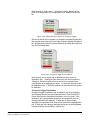
programmed into the matrix system. Right click on the logic elements
in the Logic Elements pane to display an options menu. This menu
allows the user to display a truth table for the logic element or copy the
logic element to the design window.
Logic elements can be inserted existing connections by right-clicking
on the connection to display the options menu and selecting ‘Insert
Gate Type’. A list of logic elements will be displayed for insertion into
the connection.
Figure 1-76: Inserting a Logic Element into a Connection
The logic elements available are described below.
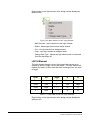
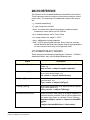
AND Gate
Combines two or more inputs to generate a single output. The default
is two inputs but by right clicking on the AND gate to display the
options menu additional inputs can be added. Unused inputs will
default to the TRUE state. The output is only true if all the inputs are
true. The AND gate adds a 25ms processing delay.
Input A
Input B
Output
False
False
False
False
True
False
True
False
False
True
True
True
Table 1-1: Truth Table for AND Logic Element
1-42
Clear-Com
Eclipse Logic Maestro Instruction Manual
Right clicking on the logic element in the design window displays an
options menu.
Figure 1-77: Menu Options for AND Logic Element
• Add Comment - add a comment to the logic element.
• Delete - delete logic element from design window.
• Cut - cut logic element from design window.
• Copy - copy logic element on design window.
• Add Input - add an input to the logic element.
• Change Gate Type - replace the logic element with one selected
from the drop-down list.
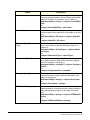
NAND Gate
Combines two or more inputs to generate a single output. The default
is two inputs but by right clicking on a NAND gate to display the menu
additional inputs can be added. Unused inputs will default to the
TRUE state. The output is only true if at least one input is false. The
NAND gate adds a 25ms processing delay.
Input A
Input B
Output
False
False
True
False
True
True
True
False
True
True
True
False
Table 1-2: Truth Table for NAND Logic Element
Clear-Com
Eclipse Logic Maestro Instruction Manual
1-43
Right clicking on the logic element in the design window displays an
options menu.
Figure 1-78: Menu Options for NAND Logic Element
• Add Comment - add a comment to the logic element.
• Delete - delete logic element from design window.
• Cut - cut logic element from design window.
• Copy - copy logic element on design window.
• Add Input - add an input to the logic element.
• Change Gate Type - replace the logic element with one selected
from the drop-down list.
OR Gate
Combines two or more inputs to generate a single output. The default
is two inputs but by right clicking on an OR gate to display the menu
additional inputs can be added. Unused inputs will default to the
TRUE state. The output is only true if one or more inputs are true. The
OR gate adds a 25ms processing delay.
Input A
Input B
Output
False
False
False
False
True
True
True
False
True
True
True
True
Table 1-3: Truth Table for OR Logic Element
Right clicking on the logic element in the design window displays an
options menu.
1-44
Clear-Com
Eclipse Logic Maestro Instruction Manual
Figure 1-79: Menu Options for OR Logic Element
• Add Comment - add a comment to the logic element.
• Delete - delete logic element from design window.
• Cut - cut logic element from design window.
• Copy - copy logic element on design window.
• Add Input - add an input to the logic element.
• Change Gate Type - replace the logic element with one selected
from the drop-down list.
NOR Gate
Combines two or more inputs to generate a single output. The default
is two inputs but by right clicking on a NOR gate to display the menu
additional inputs can be added. Unused inputs will default to the
TRUE state. The output is only true if all inputs are false. The NOR
gate adds a 25ms processing delay.
Input A
Input B
Output
False
False
True
False
True
False
True
False
False
True
True
False
Table 1-4: Truth Table for NOR Logic Element
Right clicking on the logic element in the design window displays an
options menu.
Clear-Com
Eclipse Logic Maestro Instruction Manual
1-45
Figure 1-80: Menu Options for NOR Logic Element
• Add Comment - add a comment to the logic element.
• Delete - delete logic element from design window.
• Cut - cut logic element from design window.
• Copy - copy logic element on design window.
• Add Input - add an input to the logic element.
• Change Gate Type - replace the logic element with one selected
from the drop-down list.
BUFFER Element
Used between a crosspoint trigger and a crosspoint action to reduce
the system resource usage. There is a constraint on the maximum
number of possible actions by crosspoint triggers and crosspoint
actions imposed by system resources. In general the number of
possible triggers times the number of possible actions should not
exceed 4095. So if there are 16 possible triggers specified in a
crosspoint trigger and 16 possible crosspoint actions specified in a
crosspoint action the number of actions would be:
16 triggers x 16 actions = 256 events
which would be acceptable. If the result of setting up a system of
crosspoint triggers and crosspoint actions created more than 4095
possible actions an error would be reported when the configuration
was downloaded.
In this case a buffer logic element should be placed between the
crosspoint trigger and crosspoint action. In this way the number of
actions the trigger crosspoint has to make is limited to the number of
trigger crosspoints, which only have to trigger the buffer. The buffer
will then act on the crosspoints in the crosspoint action.
The BUFFER element adds a 25ms processing delay.
1-46
Clear-Com
Eclipse Logic Maestro Instruction Manual
Input A
Output
False
False
True
True
Table 1-5: Truth Table for BUFFER Logic Element
Right clicking on the logic element in the design window displays an
options menu.
Figure 1-81: Menu Options for BUFFER Logic Element
• Add Comment - add a comment to the logic element.
• Delete - delete logic element from design window.
• Cut - cut logic element from design window.
• Copy - copy logic element on design window.
• Change Gate Type - replace the logic element with one selected
from the drop-down list.
NOT Element
A NOT element inverts the input so that when the input is OFF the
output is ON; when the input is ON the output is OFF. The NOT
function adds a 25ms processing delay.
Input A
Output
False
True
True
False
Table 1-6: Truth Table for NOT Logic Element
Clear-Com
Eclipse Logic Maestro Instruction Manual
1-47
Right clicking on the logic element in the design window displays an
options menu.
Figure 1-82: Menu Options for NOT Logic Element
• Add Comment - add a comment to the logic element.
• Delete - delete logic element from design window.
• Cut - cut logic element from design window.
• Copy - copy logic element on design window.
• Change Gate Type - replace the logic element with one selected
from the drop-down list.
LATCH Element
The latch element creates a true or false output that can be set or
cleared by inputs to toggle, set or reset inputs. The latch element will
maintain the state it is set to until that state is changed via a set, reset
or toggle.
Reset
Set
Toggle
Q
/Q
True
X
X
False
True
False
True
X
True
False
False
False
F -> T
/Q
Q
X
False
T -> F
Q
/Q
Table 1-7: Truth Table for LATCH Logic Element
Right clicking on the logic element in the design window displays an
options menu.
1-48
Clear-Com
Eclipse Logic Maestro Instruction Manual
Figure 1-83: Menu Options for LATCH Logic Element
• Add Comment - add a comment to the logic element.
• Delete - delete logic element from design window.
• Cut - cut logic element from design window.
• Copy - copy logic element on design window.
The latch element can be used with the toggle input only connected
and the set and reset inputs not connected. In this case the latch will
change state when it is toggled by an external input. The toggle
operates on the rising edge of an input so if the input goes to true the
latch will toggle to the opposite to its current state. When the toggle
input goes false the latch will remain in its current state until the toggle
input goes true again.
Clear-Com
Eclipse Logic Maestro Instruction Manual
1-49
Figure 1-84: Latch Sequence Using Toggle
This allows a toggle input to toggle normal and inverted outputs so that
input events will enable outputs which then remain enabled until the
latch is toggled again or reset.
An example of using the latch with toggle, set and reset connected is
shown in Figure 1-85.
1-50
Clear-Com
Eclipse Logic Maestro Instruction Manual
Figure 1-85: Latch Example using All Inputs
The LATCH function adds a 25ms processing delay.
ENABLE Element
The ENABLE logic element allows a logic true or always on input to be
placed in a control sequence design. This allows control sequences to
be created with temporary external inputs or stubs which are known to
be always on. This logic element is useful for testing the logic design.
Figure 1-86: Menu Options for Enable Logic Element
• Add Comment - add a comment to the logic element.
• Delete - delete logic element from design window.
• Cut - cut logic element from design window.
Clear-Com
Eclipse Logic Maestro Instruction Manual
1-51
• Copy - copy logic element on design window.
• Change Gate Type - replace the logic element with one selected
from the drop-down list.
DISABLE Element
The DISABLE logic element allows a logic false or always off input to
be placed in a control sequence design. This allows control sequence
designs to be created with temporary external inputs or stubs which
are known to be always off. This logic element is useful for testing the
logic design.
Figure 1-87: Menu Options for Disable Logic Element
• Add Comment - add a comment to the logic element.
• Delete - delete logic element from design window.
• Cut - cut logic element from design window.
• Copy - copy logic element on design window.
• Change Gate Type - replace the logic element with one selected
from the drop-down list.
Some Example of the use of logic elements are shown in Figure 1-88.
1-52
Clear-Com
Eclipse Logic Maestro Instruction Manual
Figure 1-88: AND, NAND and BUFFER Logic Elements
Clear-Com
Eclipse Logic Maestro Instruction Manual
1-53
1-54
Clear-Com
Eclipse Logic Maestro Instruction Manual
A
APPENDIX A
CONTROL MACRO
EDITOR
INTRODUCTION TO CONTROL MACRO
EDITOR
Control macros allow the configuration map that controls the matrix
operation to be directly modified via control macros. Each control
macro contains a series of commands with each defined command
representing an action carried out on an object in the configuration. An
object may be a port, an input or output device or label.
The main use of control macro scripts is to select controls which have
already been configured using the ECS client, and modify the actions
that they trigger when activated.
Each defined command is named and can have multiple inputs and
outputs and combination logic. These commands take the form of
actions to be associated with controls, and the control macro editor will
assist the author by providing an overview of available actions and the
parameters each requires in order to function.
Conditional logic is available (i.e. with AND, OR logic), with examples
and code hints supplied by the control macro editor environment.
Examples of the use of control macros when coupled with ECS
Controls and port configuration are:
• To enable or disable a route between any source and a named
destination which may be conditional on the status of other
Controls, Route based Controls or GPIs.
• To enable or disable a named panel’s loudspeaker (dimming/ muting)
• To remotely enable a named panel’s microphone muting
• To remotely enable a named panel’s headset/ microphone selection
• To remotely enable a named panel’s nominated Key LED signal
activation
• To remotely enable a named panel’s nominated Relay control
The control macro editor enables the user to:
• Define control macros
• Reference control macros by name
Clear-Com
Eclipse Logic Maestro Instruction Manual
A-1
• Assign named macro functions to controls
Note: Control Macros are only available to ECS V4.0 or later.
The Control Macro Application is a stand-alone application
requiring a license key.
ECS then imports the macros for use within the ECS
environment.
CONTROL MACRO LANGUAGE
The Microsoft .NET Framework is used to provide the scripting facility
through the use of dynamic code generation (CodeDOM). This
provides the facility to compile control macro into a binary file (an
Assembly) rather than the more traditional ‘interpreted’ control macro
of other languages such as VBScript.
Using the .NET Framework as the scripting environment provides the
stability and support that the framework has, along with gaining from
the .NET Framework features of:
• Managed application environment
• Garbage collector memory management
• Control macros are written in C#
A-2
Clear-Com
Eclipse Logic Maestro Instruction Manual
EXAMPLE CONTROL MACRO
The following is an example of a control macro created using the
control macro editor.
Control Macro ExampleScript
using System;
// automatically generated
using ClearCom.ScriptHost;
using ClearCom.ScriptLibrary;
using ClearCom.Entities;
using EMS.MapClient;
using EMS.MapClient.Tables;
using EMS.MapClient.Tables.Actions;
namespace CustomControlMacros
{
public class CustomMacro : ScriptBase
{
public override void OnUserStart()
{
// User Script entered here
Control redLightControl = ExistingControlFromLabel(“RDLT”);
// gets an already existing Control, set up from the Control Manager within the ECS client and
allows it to be programmed
redLightControl.Triggers(new InhibitRoute(5, 6));
// When the red light control is fired (studio moves into Live mode) the route between ports 5 and
6 is
// inhibited. The control editor prompts the script author for either a port number or port name
redLightControl.Triggers(new ChangeStatus(“DIR”, HardwareStatus.LoudspeakerCut);
// changes a large number of panel properties by selecting a panel by name and then triggering a
change
redLightControl.Triggers(new ChangeStatus(“DIR”, 5);
// Changes LED 5 on panel DIR
}
}
}
Clear-Com
Eclipse Logic Maestro Instruction Manual
A-3
CONTROL MACRO EDITOR
To create and edit the Control Macro, a control macro editor is
provided. This consists of:
• A main control macro editor window
• An object browser
• A message window
An illustration of the control macro editor is shown below.
Figure A-1: Control Macro Editor Screen
CONTROL MACRO EDITOR WINDOW
The control macro editor window provides full access for editing the
control macro scripts while also providing assistance to the user in the
form of coloured syntax, ‘intellisense’ (offering context sensitive coding
options) and code completion.
OBJECT BROWSER
The Object Browser gives a complete display of the objects and logic
available to be used to construct control macros. This gives a detailed
view of all the contained objects, their constructors, methods and
properties. This view will be generated using the powerful reflection
capability that is part of the .NET Framework.
A-4
Clear-Com
Eclipse Logic Maestro Instruction Manual
MESSAGE WINDOW
The Message Window will provide feedback to the user of any
validation issues when parsing the control macro. These issues will be
flagged as either warnings or errors.
RUNNING CONTROL MACROS
Control macros are run at download time and follow a two stage
approach of validation and building of the control macro.
The validation stage checks the control macro for warnings or errors
which will be reported back to the user. Any errors will prevent the
control macro from being compiled.
When the control macro has passed the validation stage, the control
macro will be compiled into an Assembly using the Microsoft .NET
Framework code compiler. This Assembly is then cached and will only
be refreshed if the control macro itself is changed. It is then run at
download time, with the output (usually the addition of rack-specific
map objects) being sent to the frame together with the ECS-derived
configuration.
STARTING THE CONTROL MACRO EDITOR
The control macro editor is accessed from Logic Maestro by clicking
on the ‘New’ button and selecting ‘Control Macro’ from the drop-down
‘Type’ menu.
Figure A-2: Control Macro Editor from Logic Maestro
After entering the required fields click on the ‘OK’ button to open the
control macro editor.
Saved control macro files have the same file extension of .ccm as logic
maestro files and will be listed with logic maestro files. If the ‘Edit
Clear-Com
Eclipse Logic Maestro Instruction Manual
A-5
Logic’ link is selected for a control macro file the control macro editor
will be started automatically rather than the logic diagram editor.
The control macro editor can also be started using a desktop shortcut
to the executable if required but this useage is not recommended.
The Eclipse Macro facility is a licensable option and a license key is
required to use the editor to create new control macros. When the
editor is first started it will request a license key if one has not already
been input.
Figure A-3: License Key Request
Enter the license key obtained from the supplier or distributor and click
on the ‘OK’ button to continue and start the control macro editor. If a
valid license key is not entered the control macro editor will exit
immediately.
Note: When running under Windows Vista the user must have
administrator rights in order to enter the control macro editor
license key.
When the editor is started from Logic Maestro it will display the three
windows ready to start a new control macro (if started using the ‘New’
button) or load an existing macro.
A-6
Clear-Com
Eclipse Logic Maestro Instruction Manual
Figure A-4: Initial Macro Control Macro Editor Display
Clear-Com
Eclipse Logic Maestro Instruction Manual
A-7
CONFIGURATION ENTITIES
Click on the ‘Configuration Entities’ tab of the object browser to select
the system configuration that is to be used by the control macro editor.
A drop down menu of all the available system configurations is
displayed below the window title.
Figure A-5: Configuration Selection
After a system configuration has been selected the entities that exist in
that configuration are displayed in the object browser window under
the headings:
• Gpsf - General Purpose Specific Functions
• Group - fixed groups and sort groups defined in ECS
• Port - system ports defined as Direct in ECS
• Conf - party lines (conferences) defined in ECS
• Port - system ports defined as panels in ECS
• Relay - relays that can be set open or closed
• Route - routes between panels defined in ECS
Each item can be opened to display a list of all the entities of this type
in the currently selected system configuration. If the configuration
does not include any entities of a type the heading for that entity type is
not displayed.
If a new ECS element is made while the control macro editor is
opened, then:
A-8
Clear-Com
Eclipse Logic Maestro Instruction Manual
1. In ECS Save the configuration(s).
2. Re-select the configuration(s) from the configuration task in order to
force the macro editor to refresh its copy of the configuration(s).
Figure A-6: Configuration Entities List
These entities contained in the system configuration selected may be
referenced in the control macro as required but the control macro will
be specific to that system configuration and should not be used with
any other system configuration as it may fail or produce unexpected
results.
Clear-Com
Eclipse Logic Maestro Instruction Manual
A-9
AVAILABLE MODULES
Click on the ‘Available Modules’ tab in the object browser to display the
menus for the objects used to create the macros. These are divided
into the ‘ClearCom’ modules to construct programs to modify the map
and ‘Shared’ to provide logging and debug capability.
CLEARCOM
Click on the ‘ClearCom’ item and expand the menus to show the object
classes available.
Figure A-7: ClearCom Module Libraries
Entities
The entities section is divided into Attachment Objects which are
associated with components, Control Objects that act on system
components, Entity Objects that act on the state of system
components and Port Objects that act on system ports.
A-10
Clear-Com
Eclipse Logic Maestro Instruction Manual
Figure A-8: Entity Libraries
Attachment Objects
When the attachment objects item is selected the list will be expanded
to display the attachment objects available and the logic operations
that may be used with attachment objects. Attachment objects are
attached to components to set or get the properties of those
components such as parameters.
Examples of attachment objects are relays, routes and speed dials.
Figure A-9: Attachment Objects Library
Clear-Com
Eclipse Logic Maestro Instruction Manual
A-11
To use an attachment object select the required object by right clicking
over it and then dragging it over to the edit window and dropping it in
the required position.
When an attachment object is dropped into the control macro the
editor will prompt for information such as whether the object is to set or
get the component parameter and depending on this any other
information that is required such as parameters and how to return the
information.
Figure A-10: Example of Attachment Object Properties
Control Objects
Control objects act on the components to change their properties in
some way. When a control object is dropped into the editor window
the editor will prompt for the required settings and parameters for that
object.
Control objects are controls created in ECS using the Control Manager
function accessed from the Setup Eclipse menu.
A-12
Clear-Com
Eclipse Logic Maestro Instruction Manual
Figure A-11: Control Objects List
An example of the use of a control object is:
HSON.Triggers(ControlActions.CutLoudspeaker(D4222));
where CutLoudspeaker is the control.
Entity Objects
Entity objects act on the components to change their state in some
way. When an entity object is dropped into the editor window the
editor will prompt for the required settings and parameters for that
object.
Clear-Com
Eclipse Logic Maestro Instruction Manual
A-13
Figure A-12: Entity Object List
An example of the use of an entity object is:
HSON.Triggers(ControlActions.CutLoudspeaker(D4222));
where CutLoudspeaker is the control.
Port Objects
Port objects are used to get information on a system port to change the
properties of a system port. When a port object is dropped into the the
edit window the editor will prompt for the required settings and
parameters for that object and action.
Port objects are normally ports on the system.
A-14
Clear-Com
Eclipse Logic Maestro Instruction Manual
Figure A-13: Port Object List
An example of port object use is:
PortObject D4222 = ControlMacro.GetPort(“D4222”);
where D4222 is the port object defined is Matrix Hardware.
Scriptlibrary
The scriptlibrary section is divided into Conditions which allow
components and component parameters to be tested, Control Actions
which specify actions to be carried out on system components, Control
Attachments which specify actions to be carried out on objects and
Control Macros which act on system components.
Clear-Com
Eclipse Logic Maestro Instruction Manual
A-15
Figure A-14: Script Library Categories
Condition
The condition objects allow the value or state of component
parameters to be tested, compared or converted from one format to
another. Conditions are AND and OR.
Figure A-15: Conditions List
An example of the use of a condition is:
FRLY2.Triggerslf(crosspointControl,Condition.AND,AND1);
where control FRLY2 is triggered if the elements crosspointControl and
AND1 are both true.
Control Actions
Control actions allow the states of system components such as LEDs,
actions (for example when a key is pressed) and routes to be changed
for new actions and routes to be created.
A-16
Clear-Com
Eclipse Logic Maestro Instruction Manual
Figure A-16: Control Actions List
Control Attachments
Control attachment objects allow the states of pre-existing system
components to be changed.
Clear-Com
Eclipse Logic Maestro Instruction Manual
A-17
Figure A-17: Control Attachment List
Control Latch
Control latch modules provide the functionality associated with latching
actions.
A-18
Clear-Com
Eclipse Logic Maestro Instruction Manual
Figure A-18: Control Latch Actions List
Control Macro
Control macros act on system components to get or set the states or
attributes of those components.
Clear-Com
Eclipse Logic Maestro Instruction Manual
A-19
Figure A-19: Control Macro List
Crosspoint Control
Crosspoint controls act on system crosspoints to get or set the states
of the crosspoints.
A-20
Clear-Com
Eclipse Logic Maestro Instruction Manual
Figure A-20: Crosspoint Controls
Current
Current provides facilities to obtain current system information.
Figure A-21: System Current
Clear-Com
Eclipse Logic Maestro Instruction Manual
A-21
SHARED
The shared entry provides a library of objects for debugging control,
error reporting, messages and logging from user control macros.
Figure A-22: Shared Object List
A-22
Clear-Com
Eclipse Logic Maestro Instruction Manual
CREATING A NEW PROJECT
To start a new project click on ‘File’ and then ‘New’ to display the
options to create a new control macro or project. Click on project to
create a new project and the new project folder with the default name
“Unknown” will be displayed in the object browser window.
Figure A-23: New Project Screen
A project is a collection of different control macros, usually for a
specific application such as a studio.
Double click on the ‘Project [Unknown]’ entry in the object browser to
highlight it and right-click to display the command menu and select
‘Rename’ then type in the new project name. The new project can be
saved by selecting ‘File’ and then ‘Save’ to save the project.
To start a new control macro click on ‘File’ to display the file menu,
click on ‘New’ and then ‘Control Macro’ to initialize a new control
macro.
Clear-Com
Eclipse Logic Maestro Instruction Manual
A-23
Figure A-24: Start New Control Macro
After clicking on ‘Script’ the editor will automatically create the basic
structure of the control macro with the required libraries set up at the
start of the control macro. One the initial control macro has been
created the user can start creating the application control macro under
the comment ‘// User script entered here’.
A-24
Clear-Com
Eclipse Logic Maestro Instruction Manual
Figure A-25: Inital New Control Macro
Once the control macro structure has been generated the user control
macro is created by dragging and dropping items from the object
browser into the control macro edit window to build up lines of the
control macro.
For example, to create an instance of a port select the ‘Configuration
Entities’ tab and open the ‘PORT’ item to display a list of ports. Right
click on the required port to select it and then double click to
automatically create the line of code that will create and instance of
that object.
Note: Enter some blank lines (keyboard Enter) after automatically
generated ‘// user Script entered here’ line
Note: Make sure the cursor is placed on a line under the start of
the user script marker before selecting a new control control
macro line.
Certain types of macro actions may have variable or unpredictable
effects on different types of hardware so where a macro may act on
different types of hardware it should be checked on all the variants of
the hardware.
Once such case is macros which cause LEDs on panels to flash.
There are a variety of different panel types which may be present on a
system and they may respond differently to commands to flash LEDs.
For example a macro to cause LEDs to flash system wide will not work
on ICS-2003 panels but will work on other panels. Macros which flash
Clear-Com
Eclipse Logic Maestro Instruction Manual
A-25
LEDs at various frequencies may work on some panels but not on
others. Generally a 1Hz flash is likely to work.
Macros may also reference keys on panels but it should be noted that
the key numbering is different on different panels so any control macro
will need to take account of this if there is more than one type of panel
on a system. The key numbering on the various panel types is given in
Appendix C.
Figure A-26: Control Macro with Port Commands
In this way commands to create instances of configuration objects can
be created. These instances can then to referenced by other
commands to modify the source system configuration.
The user may also create control macros manually using a text editor
such as Notepad but this is not normally recommended as the error
checking facilities of the control macro editor will not be available.
When a control macro is dragged and dropped into the control macro
editor window a configuration window is opened to request the
parameters that are required for that control macro. Where there are a
number of predetermined values for a parameter such as TRUE or
FALSE a drop-down menu allows a parameter to be selected.
Alternatively a parameter name can be entered manually.
A-26
Clear-Com
Eclipse Logic Maestro Instruction Manual
Figure A-27: Macro Parameter Entry Window
When the parameters have been input clicking on ‘OK’ writes the new
line into the control macro editor window at the current cursor position.
Any errors in the command for example as a result of an incorrect
parameter will be reported in the compilation messages window below
the control macro editor window.
ELEMENTS OF A CONTROL MACRO
There are three basic steps to create a control function using the
control macro facility. These are:
1. Set the objects the macros are to operate on. These may be ports
or entities such as groups or conferences. For example, to create a
port object that references a specific port select the ‘Configuration
Entities’ tab in the object browser window and open the ‘Port’ item to
display a list of ports in the current configuration. Double click on
the required port to create the macro in the control macro editor
window e.g.
PortObject var_myPortt = ControlMacro.GetPort(“MyPort”);
where ‘MyPort’ is the name of the port defined in ECS. Alternatively
port objects can be created by selecting the ‘Available Modules’ tab
in the object browser and opening the Scriptlibrary.ControlMacro
menu and selecting the ‘Getport (string)’ macro. Ports may be
selected by port name (string parameter), port number (integer
parameter) or by global identifier (Guid).
Clear-Com
Eclipse Logic Maestro Instruction Manual
A-27
2. Create an action to perform. Select the ‘Available Modules’ tab in
the object browser window and open the Scriptlibrary ControlActions
menu. Actions which use the objects previously created can be
dragged and dropped into the control macro. For example the
action to activate an LED can be created using a port object created
in step 1.
LEDDisplayAction MyLED =
ControlAction.ActivateLED(MyPortObject,1);
will create an action ‘MyLED’ to activate the LED on key 1 on a
panel attached to port ‘MyPort’.
3. Create a control object which will be used to trigger the action set up
in step 2. For example a control action could be created using a
general purpose I/O port by selecting the ‘Configuration Entities’ tab
and opening the ‘GPSF’ item to display a list of GPSF items.
Double click on the required item to create the control macro in the
control macro editor window e.g.
ControlMacro MyControl = ControlMacro.GetControl(“MyGPSF”);
4. Trigger the action. To do this a control must be created which
connects an event on the system with the action that has been
created. For example, a control can be created for another port e.g.
MyControl.Triggers(MyLED);
so that an event on the GPSF ‘MyGPSF’ will trigger the LED on key
1 of the panel attached to ‘MyPort’.
A-28
Clear-Com
Eclipse Logic Maestro Instruction Manual
MACRO REFERENCE
The objects from the Available Modules are described in this section.
These macros are used to construct control macros using the control
macro editor. The meanings of the parameters used by the macros
are:
• () - required parameter(s)
• [] - type of argument returned
• object - the name of the object being tested, normally an object
created by a control macro such as ‘GetPort’
• bool - boolean operator, set to True or False
• int - integer value in the range 0 - 32767
• string - alphanumeric string parameter
• Guid - an ECS internal global identifier. Every entity has a unique
internal identifier and while these may be used as input parameters
for some control macros they are not generally used.
ATTACHMENTOBJECT MACROS
These macros are accessed by expanding the ‘Clearcom’ > ‘Entities’ >
‘AttachmentObject’ entry in the Available Modules menu.
Macro
Description
Equals (object) [bool]
Tests the equivalence of two objects and returns True or
False. e.g.
bool <result> = <object1>.equals<(object2)>;
GetHashCode () [int]
Returns the hash code of an object previously created
by a control as an integer. e.g.
int <result> = <object>.GetHashCode();
GetType () [Type]
Returns the type of an object previously created by a
control macro. e.g.
Type <result> = <object>.GetType();
ToString () [string]
Returns the string value of an object previously created
by a control macro. e.g.
string <result> = <object>.ToString();
ActivateWithListen [bool]
Either returns the listen status of an object created by a
control macro as a boolean True or False or sets the listen status of an object to a boolean True or False e.g.
AttachmentObject <result> = <object>.ActivateWithListen;
or
<object>.ActivateWithListen = <listen state>;
Clear-Com
Eclipse Logic Maestro Instruction Manual
A-29
Macro
A-30
Description
ActivateWithTalk [bool]
Either returns the talk status of an object created by a
control macro as a boolean True or False or sets the talk
status of an object to a boolean True or False e.g.
AttachmentObject <result> = <object>.ActivateWithTalk;
or
<object>.ActivateWithTalk = <talk state>;
AttachID [Guid]
Either returns the ID of an object created by a control
macro as type Guid or sets the ID of an object to a Guid
e.g.
AttachmentObject <ID result> = <object>.AttachID;
or
<object>.AttachID = <ID value>;
AttachmentType [AttachmentType]
Either returns the attachment type of an object created
by a control macro or sets the attachment type of an
object e.g.
AttachmentObject <AttachType> = <object>.AttachmentType;
or
<object>.AttachmentType = <AttachType>;
ConfigurationID [Guid]
Either returns the configuration ID of an object created
by a control macro as type Guid or sets the configuration ID of an object to a Guid e.g.
AttachmentObject <configID> = <object>.ConfigurationID;
or
<object>.ConfigurationID = <configID>;
Description [string]
Either returns the description of an object created by a
control macro as a string or sets the description of an
object to a string e.g.
AttachmentObject <string> = <object>.Description;
or
<object>.Description = <string>;
DTMFAutoDialSeq [string]
Either returns the auto dial sequence (number) of an
object created by a control macro as a string or sets the
auto dial sequence (number) of an object to a string
e.g.
AttachmentObject <string> = <object>.DTMFAutoDialSeq;
or
<object>.DTMFAutoDialSeq = <string>;
Clear-Com
Eclipse Logic Maestro Instruction Manual
Macro
Description
IsStnRelay [bool]
Either returns whether the status of an object created by
a control macro is a station relay as a boolean True or
False or sets the status of an object as a station relay to
a boolean True or False e.g.
AttachmentObject <result> = <object>.IsStnRelay;
or
<object>.IsStnRelay = <boolean>;
ModuleNumber [int]
Either returns the module number of an object created
by a control macro as an integer value or sets the module number of an object to an integer value e.g.
AttachmentObject <integer> = <object>.ModuleNumber;
or
<object>.ModuleNumber = <integer>;
OutputNumber [int]
Either returns the output number of an object created by
a control macro as an integer value or sets the output
number of an object to an integer value e.g.
AttachmentObject <integer> = <object>.OutputNumber;
or
<object>.OutputNumber = <integer>;
RelayInformation [string]
Either returns the relay information of an object created
by a control macro as a string or sets the relay information of an object to a string e.g.
AttachmentObject <string> = <object>.RelayInformation;
or
<object>.RelayInformation = <string>;
ReverseListen [bool]
Either returns the reverse listen status of an object created by a control macro as a boolean True or False or
sets the reverse listen status of an object to a boolean
True or False e.g.
AttachmentObject <boolean> =
<object>.ReverseListen
or
<object>.ReverseListen = <boolean>
RouteDestID [Guid]
Either returns the route destination ID of an object created by a control macro as type Guid or sets the route
destination ID of an object to a Guid e.g.
AttachmentObject <destID> = <object>.RouteDestID
or
<object>.RouteDestID = <destID>
Clear-Com
Eclipse Logic Maestro Instruction Manual
A-31
Macro
RouteSourceID [Guid]
A-32
Description
Either returns the route source ID of an object created
by a control macro as type Guid or sets the route source
ID of an object to a Guid e.g.
AttachmentObject <sourceID> = <object>.RouteSourceID
or
<object>.RouteSourceID = <sourceID>
Clear-Com
Eclipse Logic Maestro Instruction Manual
CONTROL OBJECT MACROS
These macros are accessed by expanding the ‘Clearcom’ > ‘Entities’ >
‘ControlObject’ entry in the Available Modules menu.
Macro
Description
Dispose () [void]
Disposes of an object created by a control macro e.g.
<object>.Dispose();
Equals (Object) [bool]
Tests the equivalence of two objects and returns True or
False. e.g:
bool <result> = <object1>.equals<(object2)>;
GetGPSF () [GPSF]
Gets the GPSF e.g.
GPSF <result> = <object>.GetGPSF();
GetGPSF (TalkType) [GPSF]
Gets the talk type for GPSF e.g.
GPSF <result> = <object>.GetGPSF(<talk type>);
GetHashCode () [int]
Returns the hash code of an object previously created
by a control as an integer. e.g:
int <result> = <object>.GetHashCode();
GetID (TalkType) [Guid]
Returns the Guid of the talk/listen status of an object
created by a control macro e.g.
Guid <return> = <object>.GetID(<talk/listen type>);
GetOwnerSystemGPSF(TalkType) [GPSF]
Returns the GPSF of an object specified by TalkType
e.g.
GPSF <return> = <object>.GetOwnerSystemGPSF(TalkType.<talk/listen type>);
GetOwnerSystemRackOffset(TalkType) [ushort]
Returns the rack number of an object specified by TalkType e.g.
ushort <return> = <object>.GetOwnerSystemRackOffset(TalkType.<talk/listen type>);
GetRackOffset () [ushort]
Returns an offset value as an unsigned short for the
object previously created by a control macro e.g.
ushort <value> = <object>.GetRackOffset();
GetRackOffset (TalkType) [ushort]
Returns an offset value as an unsigned short for the
object previously created by a control macro where the
type of route is specified ie Talk and/or Listen e.g.
ushort <value> = <object>.GetRackOffset(<type>);
GetType () [Type]
Returns the type of an object previously created by a
control macro. e.g.
Type <result> = <object>.GetType();
Clear-Com
Eclipse Logic Maestro Instruction Manual
A-33
Macro
A-34
Description
SetGPSF (TalkType, GPSF)
[void]
Sets the talktype GPSF e.g.
GPSF <result> = <object>.SetGPSF(<talk
type>,<GPSF>);
SetID (Guid, TalkType) [void]
Sets the ID of the talk/listen status of an object created
by a control macro e.g.
Guid <return> = <object>.GetID(<talk/listen type>);
SetOwnerSystemGPSF(TalkType,GPSF) [void]
Sets the GPSF of the object specified by TalkType e.g.
<object>.SetOwnerSystemGPSF(TalkType.<talk/listen type>, GPSF);
TalkTypeIsCreated(TalkType)
[bool]
Creates an object TalkType and returns the result as a
boolean e.g.
bool <result> = <object>.TalkTypeIsCreated(TalkType.<talk/listen type>);
ToString () [string]
Returns the string value of an object previously created
by a control macro. e.g.
string <result> = <object>.ToString();
ConfigurationID [Guid]
Sets or returns the configuration ID of an object created
by a control macro as a control object e.g.
ControlObject <ID object> = <object>.ConfigurationID;
or
<object>.ConfigurationID = <ID object>;
EntityID [Guid]
Sets or returns the entity ID of an object created by a
control macro as a Guid e.g.
ControlObject <Guid> = <object>.EntityID;
or
<object>.EntityID = <Guid>;
EntityType [dest_type_e]
Returns the entity type of an object created by a control
macro as a Guid e.g.
ControlObject <object> = <object>.EntityType;
IsCreated [bool]
Returns a boolean indicating whether an object created
by a control macro has been created e.g.
ControlObject <bool> = <object>.IsCreated;
LatchDisable [bool]
Sets or returns the latch disable status of an object created by a control macro e.g.
ControlObject <bool> = <object>.LatchDisable;
or
<object>.LatchDisable = <bool>;
Clear-Com
Eclipse Logic Maestro Instruction Manual
Macro
Description
ListenAlias [string]
Sets or returns the listen alias of an object created by a
control macro e.g.
ControlObject <string> = <object>.ListenAlias;
or
<object>.ListenAlias = <string>;
ListenLabel [string]
Sets or returns the listen label of an object created by a
control macro e.g.
ControlObject <string> = <object>.ListenLabel;
or
<object>.ListenLabel = <string>;
TalkAlias [string]
Sets or returns the talk alias of an object created by a
control macro e.g.
ControlObject <string> = <object>.TalkAlias;
or
<object>.TalkAlias = <string>;
TalkLabel [string]
Sets or returns the talk label of an object created by a
control macro e.g.
ControlObject <string> = <object>.TalkLabel;
or
<object>.TalkLabel = <string>;
Clear-Com
Eclipse Logic Maestro Instruction Manual
A-35
PORT OBJECT MACROS
These macros are accessed by expanding the ‘Clearcom’ > ‘Entities’ >
‘PortObject’ entry in the Available Modules menu.
Macro
A-36
Description
Equals (Object) [bool]
Tests the equivalence of two objects and returns True or
False. e.g:
bool <result> = <object1>.equals<(object2)>
GetHashCode () [int]
Returns the hash code of an object previously created
by a control as an integer. e.g:
int <result> = <object>.GetHashCode()
GetType () [Type]
Returns the type of an object previously created by a
control macro. e.g.
Type <result> = <object>.GetType()
ToString () [string]
Returns the string value of an object previously created
by a control macro. e.g.
string <result> = <object>.ToString();
CC_ADV_TYPE [Destination
Type]
Gets or sets the port type according to the parameter
details selected from a menu e.g.
<port object>.CC_ADV_TYPE = <Destination
Type>.CC_ADV_PORT;
CombinedLabel[string]
Returns the port Talk/Listen label specified by the string
e.g.
PortObject <resultstring> = <port object>.CombinedLabel;
ConfigurationID [Guid]
Sets or returns the configuration ID of an object created
by a control macro as a control object e.g.
ControlObject <ID object> = <object>.ConfigurationID;
or
<object>.ConfigurationID = <ID object>;
Description [string]
Sets or returns the description of a port as a string e.g.
<port object>.Description = <description string>;
or
PortObject <string> = <port object>.Description;
EnableListenAssign [bool]
Sets or returns the permission to assign a port as Listen
using a boolean e.g.
<port object>.EnableListenAssign = True;
or
PortObject <boolean> = <port object>.EnableListenAssign;
Clear-Com
Eclipse Logic Maestro Instruction Manual
Macro
Description
EnableTalkAssign [bool]
Sets or returns the permission to assign a port as Listen
using a boolean e.g.
<port object>.EnableTalkAssign = True;
or
PortObject <boolean> = <port object>.EnableTalkAssign;
EntityID [Guid]
Sets or returns the entity ID of an object created by a
control macro as a Guid e.g.
ControlObject <Guid> = <object>.EntityID;
or
<object>.EntityID = <Guid>;
EntityType [dest_type_e]
Returns the entity type of an object created by a control
macro as a Guid e.g.
ControlObject <object> = <object>.EntityType;
GlobalIfb [bool]
Gets or sets the global IFB (Interruptable foldback) on a
port e.g.
<port object>.GlobalIfb = True;
or
PortObject <boolean result> = <port object>.GlobalIfb;
GlobalIso [bool]
Gets or sets the global ISO on a port e.g.
<port object>.GlobalIso = <boolean>;
or
PortObject <boolean result> = <port object>.GlobalIso;
LatchDisable [bool]
Sets or returns the latch disable status of an object created by a control macro e.g.
ControlObject <bool> = <object>.LatchDisable;
or
<object>.LatchDisable = <bool>;
ListenAlias [string]
Sets or returns the listen alias of an object created by a
control macro e.g.
ControlObject <string> = <object>.ListenAlias;
or
<object>.ListenAlias = <string>;
ListenLabel [string]
Sets or returns the listen label of an object created by a
control macro e.g.
ControlObject <string> = <object>.ListenLabel;
or
<object>.ListenLabel = <string>;
Clear-Com
Eclipse Logic Maestro Instruction Manual
A-37
Macro
A-38
Description
PortNumber [ushort]
Sets or returns the port number of an object created by
a control macro as an unsigned short e.g.
ushort <portno> = <object>.PortNumber;
or
<object>.PortNumber = <portno>;
PortSubType [EntityType]
Sets or returns the port subtype of an object created by
a control macro as a port subtype entity e.g.
PortObject <portsubtype> = <object>.PortSubType;
or
<object>.PortSubType = <portsubtype>;
PortType [BasicType]
Sets or returns the port type of an object created by a
control macro as a port type entity e.g.
PortObject <type> = <object>.PortType;
or
<object>.PortType = BasicType.<type>;
PreventReplySignalisation [bool]
Sets the status of the prevent reply signalization setting
for the port using the boolean e.g.
<port object>.PreventReplySignalization = True;
PreventTally [bool]
Sets or returns the status of the prevent tally setting for
the port using the boolean e.g.
<port object>.PreventTally = False;
or
PortObject <result> = <port object>.PreventTally;
ProtectPortAssignment [bool]
Sets or returns the status of the port protection setting
for the port using the boolean e.g.
<port object>.ProtectPortAssignment = True;
or
PortObject protectPortAssignment = <port
object>.ProtectPortAssignment;
SecondaryAction [Guid]
Sets or returns the secondary action of an object created by a control macro e.g.
Guid <return> = <object>.SecondaryAction;
or
<object>.SecondaryAction = <Guid>;
SplitLabel [bool]
Sets or returns the split label status of a port using the
boolean e.g.
<port object>.SplitLabel = True;
or
PortObject <relult boolean> = <port object>.SplitLabel;
Clear-Com
Eclipse Logic Maestro Instruction Manual
Macro
Description
StackedKey [bool]
Sets or returns a boolean indicating whether a key is a
stacked key e.g.
bool <return> = <object>.StackedKey;
or
<object>.StackedKey = <bool>;
TalkAlias [string]
Sets or returns the talk alias of an object created by a
control macro e.g.
ControlObject <string> = <object>.TalkAlias;
or
<object>.TalkAlias = <string>;
TalkLabel [string]
Sets or returns the talk label of an object created by a
control macro e.g.
ControlObject <string> = <object>.TalkLabel;
or
<object>.TalkLabel = <string>;
VoxAction [Guid]
Sets or returns the vox action of an object created by a
control macro e.g.
Guid <Guid> = <object>.VoxAction;
or
<object>.VoxAction = <Guid>;
Clear-Com
Eclipse Logic Maestro Instruction Manual
A-39
CONDITION MACROS
These macros are accessed by expanding the ‘Clearcom’ > ‘ScriptLibrary’ >
‘Condition’ entry in the Available Modules menu.
Macro
A-40
Description
CompareTo (Object) [int]
Returns an integer value from the comparison of two
objects e.g.
int <result> = <object1>.CompareTo(<object2>);
Equals (Object) [bool]
Tests the equivalence of two objects and returns True or
False. e.g:
bool <result> = <object1>.equals<(object2)>;
GetHashCode () [int]
Returns the hash code of an object previously created
by a control as an integer. e.g:
int <result> = <object>.GetHashCode();
GetType () [Type]
Returns the type of an object previously created by a
control macro. e.g.
Type <result> = <object>.GetType();
GetTypeCode () [TypeCode]
Returns the type code of an object previously created by
a control macro. e.g.
TypeCode <result> = <object>.GetTypeCode();
ToString () [string]
Returns the string value of an object previously created
by a control macro. e.g.
string <result> = <object>.ToString();
ToString (IFormatProvider)
[string]
Returns the string value of an object previously created
by a control macro formatted by a format specifier e.g.
string <result> = <object>.ToString(<format>);
ToString (string) [string]
Returns the string value of an object previously created
by a control macro formatted by a format provded as a
parameter e.g.
string <result> = <object>.ToString(<format>);
ToString (string, IFormatProvider) [string]
Returns the string value of an object previously created
by a control macro formatted by a format provded as two
parameters e.g.
string <result> = <object>.ToString(<format>,<format>);
AND [Condition]
Specifies a condition to tested between two objects and
returns a boolean TRUE or False e.g.
<object1>,Condition.AND,<object2>;
OR [Condition]
Specifies a condition to tested between two objects and
returns a boolean TRUE or FALSE eg.
<object1>,Condition.OR,<object2>;
Clear-Com
Eclipse Logic Maestro Instruction Manual
Macro
Description
value__ [int]
Returns the value of a condition eg.
Condition <result> = <condition>.value__;
CONTROL ACTIONS MACRO
Control action macros act on system configuration objects to change
the state of the object. The format of a control action macro command
is:
ControlActions.<Macroname><parameters>;
The ‘ControlActionMacro’ command is used to change the state of a
system configuration object
For example, the command:
Action fireLed1 = ControlActions.ActivateLED(<parameters>);
will create an action ‘fireLED1’ that changes the state of the system
object LED1 in accordance with the parameters supplied.
These macros are accessed by expanding the ‘Clearcom’ >
‘ScriptLibrary’ > ‘ControlActions’ entry in the Available Modules menu.
Macro
Description
ActivateLED(EntityObject,
LedRate, LedIndication) [Action]
Returns a control object to set the flash rate and color
for a specified LED e.g.
Action = ControlActions.ActivateLED(<EntityObject>, Ledrate, Off, LedIndications.Red);
ActivateLED (EntityObject[],
LedRate, LedIndication) [Action]
Returns a control object to set the flash rate and color
for specified LED e.g.
Action = ControlActions.ActivateLED(<EnityObject>, LedRate.Off, LedIndictions.Red);
ActivateLED (PortObject, EntityObject, LedRate, LedIndication)
[Action]
Returns a control object to set the flash rate and color
for a specified LED on a specified port e.g.
Action = ControlActions.ActivateLED(<port object>,
<Entity Object>, LedRate.Off, LedIndication.Red);
Clear-Com
Eclipse Logic Maestro Instruction Manual
A-41
Macro
A-42
Description
ActivateLED (PortObject, ushort) [LEDDisplayAction]
Returns a control object to activate a LED on a specified
port and key number e.g.
LEDDisplayAction <result> = ControlActions.ActivateLED(<port object>,<key number>);
ActivateLed (PortObject, ushort,
ushort, ushort) [LEDDisplayAction]
Returns a control object to activate a LED on a specified
port, key number, key region and key page e.g.
LEDDisplayAction <result> = ControlActions.ActivateLED(<port object>,<key number>, key
region>,<key page>);
ActivateLED (PortObject, ushort, ushort, ushort, LedRate,
LedIndication) {LEDDisplayAction]
Returns a control object to activate a LED on a specified
port, key number, key region, key page, LED rate and
LED colour e.g.
LEDDisplayAction <result> = ControlActions.ActivateLED(<port object>,<key number>, key
region>,<key page>, <LED rate>,<LED colour>);
The parameters <LED rate> and <LED colour> may be
selected from a drop-down menu or specified as a number.
ActivateLED (PortObject, ushort, ushort, ushort, bool,
LedRate, LedIndication) [LEDDisplayAction]
Returns a control object to activate a LED on a specified
port, key number, key region, key page, LED rate and
LED colour e.g.
DisplayAction <action name> = ControlActions.ActivateLED(<port name>, <key number>, <Key
Region>, <Key Page>, LedRate.Off, LedIndication.Green);
The parameters <LED rate> and <LED colour> may be
selected from a drop-down menu or specified as a number.
CallSignalAction () [CallSignalAction]
Returns an object that can be used to call action functions e.g.
CallSignalAction <object> = ControlActions.CallSignalAction ();
Control (ControlMacro) [Action]
Returns the result of a control action e.g.
Action <result> = ControlActions.Control(<action>);
Control (ControlMacro, Bits)
[Action]
Returns the result of a control action e.g.
Action <result> = ControlActions.Control(<action>,
<control bits>);
CrossPointAction () [CrossPointAction]
Returns a crosspoint action e.g.
Action <result> = ControlActions.CrosspointAction();
Clear-Com
Eclipse Logic Maestro Instruction Manual
Macro
Description
CutLoudspeaker (PortObject)
[ControlMacro]
Cuts the loudspeaker on the specified port e.g.
ControlMacro = ControlActions.CutLoudSpeaker(<port object>);
DCCAction (ushort, ushort, int)
[Action]
Returns a Digital Control Card (DCC) action e.g.
Action <result> = ControlActions.DCCAction();
Equals (Object) [bool]
Tests the equivalence of two objects and returns True or
False. e.g.
bool <result> = <object1>.equals<(object2)>;
FrameRelay (ushort) [DigitalControlCardAction]
Returns a relay action object for a specific relay on a
digital control card e.g.
DigitaControlCardAction <action> = ControlActions.FrameRelay(<relay number>);
GetHashCode () [int]
Returns the hash code of an object previously created
by a control as an integer. e.g:
int <result> = <object>.GetHashCode();
GetLogic (bool, bool, bool, bool,
bool, bool) [Bits]
Returns a bit pattern corresponding to the boolean variables e.g.
Bits <bit pattern> = ControlActions.GetLogic
(<bool>,<bool>,<bool>,<bool>,<bool>,<bool>);
GetType () [Type]
Returns the type of an object previously created by a
control macro. e.g.
Type <result> = <object>.GetType();
HeadsetSelect (portObject)
[ControlMacro]
Selects the headset on the specified port e.g.
ControlMacro = ControlActions.HeadsetSelect)(PortObject);
IsolateRoute (PortObject, PortObject) [IsolateAction]
Isolates a route between the two specified ports e.g.
IsolateAction = ControlActions.IsolateRoute(PortObject, PortObject);
LatchResetAction (ControlLatch) [Action]
Resets the specified latch to the state specified in Action
e.g.
Action = ControlActions.LatchResetAction(ControlLatch);
LatchSetAction (ControlLatch]
[Action]
Sets the specified latch to the state specified in Action
e.g.
Action = ControlActions.LatchSetupAction(ControlLatch);
LatchToggleAction (ControlLatch) [Action]
Toggles the specified latch to the state specified in
Action e.g.
Action = ControlActions.LatchToggleAction(ControlLatch);
Clear-Com
Eclipse Logic Maestro Instruction Manual
A-43
Macro
A-44
Description
LocalAction (PortObject, LocalAction) [LocalAction]
Returns a control for a local action on the specified port
e.g.
LocalAction = ControlActions.LocalAction(PortObject, LocalAction.Null);
MicMute (PortObject) [ControlMacro]
Mutes the microphone on the specified port e.g.
ControlMacro = ControlActions.MicMute(PortObject);
NewDCCAction (ushort, ushort,
int, bool) [Action]
Returns a Digital Control Card (DCC) action e.g.
Action <result> = ControlActions.NewDCCAction(<card>,<pin>,<remote system>,<station
relay>);
RouteOff (PortObject, PortObject) [Action]
Returns a new action for disabling a route between two
ports e.g.
Action <result> = ControlAction.RouteOff (<source
port object>,<destination port object>);
RouteOff (ushort, ushort, ushort)
[Action]
Returns a new action for disabling a route between two
ports e.g.
Action <result> = ControlAction.RouteOff (<source
portnumber >,<destination port number>,<source
system number>);
RouteOffPartyLine (PortObject,
EntityObject) [Action]
Returns a new action for disabling a route between two
party lines (conferences) e.g.
Action = ControlActions.RouteOffPartyLine(PortObject, EntityObject);
RouteOn (PortObject, PortObject) [Action]
Returns a new action for enabling a route between two
ports e.g.
Action <result> = ControlAction.RouteOn (<source
port object>,<destination port object>);
RouteOn (PortObject, ushort)
[Action]
Returns a new action for enabling a specified route e.g.
Action = ControlActions.RouteOn(PortObject,
<group number>);
RouteOn (ushort, ushort, ushort)
[Action]
Returns a new action for enabling a route between two
ports e.g.
Action <result> = ControlAction.RouteOn(<source
portnumber >,<destination port number>,<source
system number>);
Clear-Com
Eclipse Logic Maestro Instruction Manual
Macro
Description
RouteToGroup (ushort, ushort,
bool, bool, ushort) [Action]
Returns an action for creating a route between two
groups e.g.
Action = ControlActions.RouteToGroup(<source
port no>, <group offset number>, <talk or listen
boolean>, <permanent boolean>, <remote system
number>);
RouteToGroupAction ()
[RouteToGroupAction]
Returns an action for creating a route to a group e.g.
RouteToGroupAction <result> = ControlActions.RouteTo GroupAction();
RouteToGroupOn (ushort, ushort) [Action]
Returns an action for enabling a route between two
groups e.g.
Action = ControlActions.RouteToGroupOn(<source
port no>, <group number>);
RouteToIfbOn (PortObject, PortObject) [Action]
Returns an action for enabling a route to an IFB e.g.
Action = ControlActions.RouteToIfbOn(<source port
object>, <destination port object>);
RouteToPartyLine (portObject,
EntityObject) [Action]
Returns an action for enabling a route to a party line e.g.
Action = ControlActions.RouteToPartyLine(<source
port object>, <party line object>);
RouteToPartyLine (ushort, ushort, bool, bool, ushort) [Action]
Returns an action for enabling a route between two
party lines e.g.
Action = ControlActions.RouteToPartyLine(<source
port number>, <party line number>, <talk or listen
boolean>, <permanent boolean>, remote system
number>);
RouteToPartyLineAction ()
[RouteToPartyLineAction]
Returns an action for creating a route to a party line e.g.
RouteToPartyLineAction <result> = ControlActions.RouteTo PartyLineAction();
SourceToIfbOn (PortObject,
PortObject) [Action]
Creates an action to enable a crosspoint linking the
source and destination ports for an IFB.
PortObject s = ControlMacro.GetPort(sourceport);
PortObject d = ControlMacro GetPort(destport);
Action action;
action = ControlActions.SourceToIfbOn(s, d);
SpeedDial (PortObject, string)
[SpeedDialAction]
Returns an action for creating a speed dial with a port
object and a telephone number e.g.
SpeedDialAction <result> = ControlAction.SpeedDialAction (<port object>,<telephone number>);
Clear-Com
Eclipse Logic Maestro Instruction Manual
A-45
A-46
Macro
Description
SpeedDialAction (ushort, ushort)
[Action]
Returns an action for creating a speed dial action with a
speed dial ID and a port number e.g.
Action <result> = ControlAction.SpeedDialAction
(<speed dial ID>,<port number>);
ToString () [string]
Returns the string value of an object previously created
by a control macro. e.g.
string <result> = <object>.ToString();
Clear-Com
Eclipse Logic Maestro Instruction Manual
CONTROL ATTACHMENT MACROS
These macros are accessed by expanding the ‘Clearcom’ > ‘ScriptLibrary’ >
‘ControlAttachment’ entry in the Available Modules menu.
Macro
Description
Equals (object) [bool]
Tests the equivalence of two objects and returns True or
False. e.g.
bool <result> = <object1>.equals<(object2)>;
GetHashCode () [int]
Returns the hash code of an object previously created
by a control as an integer. e.g.
int <result> = <object>.GetHashCode();
GetType () [Type]
Returns the type of an object previously created by a
control macro. e.g.
Type <result> = <object>.GetType();
ToString () [string]
Returns the string value of an object previously created
by a control macro. e.g.
string <result> = <object>.ToString();
ActivationState [AttachmentState]
Gets or sets the listen activation state of an object e.g.
<object>.ActivateWithListen = <boolean>;
AttachmentObject [AttachmentObject]
Gets or sets the talk activation state of an object e.g.
<object>.ActivateWithTalk = <boolean>;
Clear-Com
Eclipse Logic Maestro Instruction Manual
A-47
CONTROL LATCH MACROS
These macros are accessed by expanding the ‘Clearcom’ > ‘ScriptLibrary’ >
‘ControlLatch’ entry in the Available Modules menu.
Macro
A-48
Description
CreateLatch() [ControlLatch]
Creates and returns a control latch e.g.
ControlLatch AlwaysOff = ControlLatch.CreateLatch()
Equals(Object) [bool]
Tests the equivalence of two objects and returns True or
False. e.g.
bool <result> = <object1>.equals<(object2)>;
GetHashCode() [int]
Returns the hash code of an object previously created
by a control as an integer. e.g.
int <result> = <object>.GetHashCode();
GetType() [Type]
Returns the type of an object previously created by a
control macro. e.g.
Type <result> = <object>.GetType();
ResetsWhenOff(ControlLatch)
[void]
This control latch function will reset a latch when a control input is off. The example below shows sequence to
get a control reference, create a latch and set the latch
to reset when the control input is off.
ControlMacro INPUT1 = ControlMacro.GetControl("INB", "");
ControlLatch LATCH1 = ControlLatch.CreateLatch();
LATCH1.ResetsWhenOff(INPUT1);
ResetsWhenOn(ControlLatch)
[void]
This control latch function will reset a latch when a control input is on. The example below shows sequence to
get a control reference, create a latch and set the latch
to reset when the control input is on.
ControlMacro INPUT1 = ControlMacro.GetControl("INB", "");
ControlLatch LATCH1 = ControlLatch.CreateLatch();
LATCH1.ResetsWhenOn(INPUT1);
SetsWhenOff(ControlLatch)
[void]
This control latch function will set a latch when a control
input is off. The example below shows sequence to get
a control reference, create a latch and assign the latch
to be set when the control input is off.
ControlMacro INPUT1 = ControlMacro.GetControl("INB", "");
ControlLatch LATCH1 = ControlLatch.CreateLatch();
LATCH1.SetsWhenOff(INPUT1);
Clear-Com
Eclipse Logic Maestro Instruction Manual
Macro
Description
SetsWhenOn(ControlLatch)
[void]
This control latch function will set a latch when a control
input is on. The example below shows sequence to get
a control reference, create a latch and assign the latch
to be set when the control input is on.
ControlMacro INPUT1 = ControlMacro.GetControl("INB", "");
ControlLatch LATCH1 = ControlLatch.CreateLatch();
LATCH1.SetsWhenOn(INPUT1);
TogglesWhenOff(ControlLatch)
[void]
This control latch function will toggle a latch when a control input is off. The example below shows sequence to
get a control reference, create a latch and assign the
latch to be toggled when the control input is off.
ControlMacro INPUT1 = ControlMacro.GetControl("INB", "");
ControlLatch LATCH1 = ControlLatch.CreateLatch();
LATCH1.TogglesWhenOff(INPUT1);
TogglesWhenOn(ControlLatch)
[void]
This control latch function will toggle a latch when a control input is on. The example below shows sequence to
get a control reference, create a latch and assign the
latch to be toggled when the control input is on.
ControlMacro INPUT1 = ControlMacro.GetControl("INB", "");
ControlLatch LATCH1 = ControlLatch.CreateLatch();
LATCH1.TogglesWhenOn(INPUT1);
ToString() [string]
Returns the string value of an object previously created
by a control macro. e.g.
string <result> = <object>.ToString();
TriggersWhenOff(ControlMacro] [void]
Triggers a control macro object when the input condition
is OFF e.g.
<control macro>.TriggersWhenOff(ControlMacro);
TriggersWhenOff(Action) [void]
This control latch function will trigger an action on a
crosspoint when the
ControlMacro OUTPUT1 = ControlMacro.GetControl("OUTB", "");
ControlLatch LATCH1 = ControlLatch.CreateLatch();
LATCH1.TriggersWhenOff(OUTPUT1);
Clear-Com
Eclipse Logic Maestro Instruction Manual
A-49
Macro
A-50
Description
TriggersWhenOn(ControlMacro) [void]
This control latch function will trigger an output to the
specified control when the input to the latch is on. The
example below shows sequence to get a control reference, create a latch and set the latch to trigger the control when the input is on.
ControlMacro OUTPUT1 = ControlMacro.GetControl("OUTB", "");
ControlLatch LATCH1 = ControlLatch.CreateLatch();
LATCH1.TriggersWhenOn(OUTPUT1);
TriggersWhenOn(Action) [void]
This control latch function will trigger an output to the
specified control when the input to the latch is on. The
example below shows sequence to get a control reference, create a latch and set the latch to trigger the control when the input is on e.g.
ControlMacro OUTPUT1 = ControlMacro.GetControl("OUTB", "");
ControlLatch LATCH1 = ControlLatch.CreateLatch();
LATCH1.TriggersWhenOn(OUTPUT1);
GetId [ushort]
Returns the ID of an object e.g.
ControlLatch <result> = <latch name>.GetId;
Clear-Com
Eclipse Logic Maestro Instruction Manual
CONTROL MACROS
Control macros act on system configuration objects to get or set
parameters or to change the state of the object. The format of a
control macro command is:
ControlMacro.<Macroname><parameters>;
The ‘ControlMacro’ command is used to create a copy of a system
configuration object which can then to used in the control macro.
For example, the command:
ControlMacro GP19 = ControlMacro.GetControl(“GP19”);
will create a copy of the GPIO control object called GP19 created by
ECS called GP19 which can be used in the control macro.
These macros are accessed by expanding the ‘Clearcom’ >
‘ScriptLibrary’ > ‘ControlMacro’ entry in the Available Modules menu.
Macro
Description
CreateControl (string) [ControlMacro]
Creates a control named by the string e.g.
ControlMacro AND_60 = ControlMacro.CreateControl(“AND_60”);
CreateControl(string,bool) [ControlMacro]
Creates a control named by the string with a state set by
the boolean e.g.
ControlMacro AND_60 = ControlMacro.CreateControl("AND_60", true);
Equals (Object) [bool]
Tests the equivalence of two objects and returns True or
False. e.g.
bool <result> = <object1>.equals<(object2)>;
GetAllEntities[(bool) [EntityObject[]]
Returns a list of all known entities e.g.
EntityObject[] = ControlMacro.GetAll Entities(<local
system only boolean>);
GetAllPorts() [PortObject[]]
Returns all the known ports in a system to an allay of
PortObject e.g.
PortObject[] allportsknown = ControlMacro.GetAllPorts();
GetAllPorts(bool) [PortObject[]]
Returns a list of port objects e.g.
PortObject[] = ControlMacro.GetAllPorts(<local system only boolean>);
Clear-Com
Eclipse Logic Maestro Instruction Manual
A-51
Macro
A-52
Description
GetAllStations() [PortObject[]]
Returns an array of PortObject containing all the panels
in a system e.g.
PortObject[] stationsToCut = ControlMacro.GetAllStations();
GetControl (Guid) [ControlMacro]
Gets the control information for the item named in the
string parameter e.g.
ControlMacro.<object> = ControlMacro.GetControl(<string>);
GetControl (string) [ControlMacro]
Returns a reference to a control label with the given Talk
label e.g.
ControlMacro CONTROL = ControlMacro.GetControl("CTLA ")
GetControl(string,string) [ControlMacro]
Returns a reference to a control label with the given Talk
and Listen labels e.g.
ControlMacro CONTROL = ControlMacro.GetControl("CTLA ", " ")
GetControl(string,string,int)
[ControlMacro]
Returns a reference to a control label with the given Talk
and Listen labels on the specified system e.g.
ControlMacro CONTROL = ControlMacro.GetControl("CTLA ", " ", 1)
GetEntities(string) [EntityObject[]]
Return the entities specified in the string e.g.
EntityObject[] <entity> = ControlMacro.GetEntities(“<entity names>”);
GetEntity(string) [EntityObject]
Returns the entity specified in the string e.g.
EntityObject <entity> = ControlMacro.GetEntity(<entity name>);
GetGroup(string) [EntityObject]
Returns the talk label for a group e.g.
EntityObject <entity> = ControlMacro.GetGroup(“<talk label>”);
GetGroup(string string) [EntityObject]
Returns the talk and listen labels for the group specified
as strings e.g.
EntityObject <entity> = ControlMacro.getGroup(“<talk label>”, “<listen label>”);
GetGroup(string,string,int) [EntityObject]
Returns the talk and listen labels for a group on the
given system number e.g.
EntityObject <entity> = ControlMacro.GetGroup(“<talk label>, <listen label>, <system
number>);
GetGroupMembers(EntityObject) [EntityObject[]]
Returns the members of a specified group e.g.
EntityObject[] <entity> = ControlMacro.GetGroupMembers(<group identifier>);
Clear-Com
Eclipse Logic Maestro Instruction Manual
Macro
Description
GetHashCode () [int]
Returns the hash code of an object previously created
by a control as an integer. e.g.
int <result> = <object>.GetHashCode();
GetLocalSharedListenPortNumberForRemoteEntity(PortObject) [ushort]
Returns the port number on the remote system for the
specified Listen port object e.g.
ushort <port number> = ControlMacro.GetLocalSharedListenPortNumberForRemoteEntity(<port
object>);
GetLocalSharedTalkPortNumberForRemoteEntity(PortObject) [ushort]
Returns the port number on the remote system for the
specified Talk port object e.g.
ushort <port number> = ControlMacro.GetLocalSharedTalkPortNumberForRemoteEntity(<port
object>);
GetPartyLine(string) [EntityObject]
Returns an entity for the named party line talk label e.g.
EntityObject <entity> = ControlMacro.GetPartyLine(<party line name>);
GetPartyLine(string string) [EntityObject]
Returns the talk and listen labels for the party line e.g.
EntityObject <entity> = ControlMacro.GetPartyLine(<talk label>, <listen label>);
GetPartylineMembers(EntityObject) [EntityObject[]]
Returns the members of a party line e.g.
EntityObject[] <entity> = ControlMacro.GetPartyLineMembers(EntityObject);
GetPort (Guid) [PortObject]
Gets the Guid for a port e.g.
PortObject <result> = ControlMacro.GetPort(<portGuid>);
GetPort (int) [PortObject]
Returns a reference for the specified port number e.g.
PortObject p = ControlMacro.GetPort(600)
GetPort (string) [PortObject]
Returns a reference for a port with the given Talk label
e.g.
PortObject p = ControlMacro.GetPort("Talk ")
GetPort(string string) [PortObject]
Returns the reference for a port with the given Talk and
Listen labels e.g.
PortObject p = ControlMacro.GetPort("Talk ", "Lstn
")
GetPort(string string int) [PortObject]
Returns the reference for a port with the given Talk and
Listen labels and port number e.g.
PortObject p = ControlMacro.GetPort("Talk ", "Lstn
", 600)
Clear-Com
Eclipse Logic Maestro Instruction Manual
A-53
Macro
A-54
Description
GetType () [Type]
Returns the type of an object previously created by a
control macro. e.g.
Type <result> = <object>.GetType();
Inhibits(ControlMacro) [void]
Causes a specified control action to be inhibited e.g.
<control identifier>.Inhibits(<control macro>);
Inhibits(ControlMacro, ushort)
[void]
Causes a specified control action to be inhibited e.g.
<control identifier>.Inhibits(<control macro>,<logic
parameter>);
NameExists(string) [bool]
Returns a boolean indicating whether a named entity
exists e.g.
bool <boolean> = ControlMacro.NameExists(<entity
name>);
Resets(ControlLatch) [void]
Resets the specified control latch e.g.
<entity instance>.Resets(latch name);
SetDefaultGateway(string) [void]
Sets the default gateway address 1 on a frame to the
specified string e.g.
ControlMacro.SetDefaultGateway(<default gateway
address>);
SetDefaultGateway2(string)
[void]
Sets the default gateway address 2 on a frame to the
specified string e.g.
ControlMacro.SetDefaultGateway2(<default gateway
2 address>);
Sets(ControlLatch) [void]
Set a control latch e.g.
<control latch entity>.Sets(ControlLatch);
SetSubnetMask(string) [void]
Sets the subnetmask 1 on a frame to the specified string
e.g.
ControlMacro.SetSubnetMask(<subnet mask
string>);
SetSubnetMask2(string) [void]
Sets the subnetmask 2 on a frame to the specified string
e.g.
ControlMacro.SetSubnetMask2(<subnet mask
string>);
Toggles(ControlLatch) [void]
Toggles the specified control latch e.g.
<latch instance>.Toggles(ControlLatch);
ToString () [string]
Returns the string value of an object previously created
by a control macro. e.g.
string <result> = <object>.ToString();
Clear-Com
Eclipse Logic Maestro Instruction Manual
Macro
Description
Triggers (ControlMacro) [void]
This command executes a previously defined control.
For example if an instance ‘GP23’ has been defined
using the GetControl control macro and the control
‘fireLED1’ has been defined using the ControlActions
macro the control ‘fireLED1 can be used as the parameter to the Trigger macro e.g.
GP23.Triggers (fireLED1);
Triggers (Action) [void]
This command executes a previously defined action.
For example if an instance ‘GP23’ has been defined
using the GetControl control macro and the action
‘fireLED1’ has been defined using the ControlActions
macro the action ‘fireLED1 can be used as the parameter to the Trigger macro.e.g.
GP23.Triggers (fireLED1);
TriggersIf (ControlMacro, Condition, ControlMacro) [void]
Triggers an action if the result of the condition test on
the two control macros is met e.g.
<result>.TriggersIf(<control1>,<condition>,<control2>);
Triggerslf(CrosspointControl,Condition,ControlMacro)
[void]
Triggers a crosspoint control for a specified condition
e.g.
<crosspoint>.TriggersIf(CrospointControl, <condition>, ControlMacro);
Triggerslf(CrosspointControl,Condition,CrosspointControl) [void]
Triggers a crosspoint control for a specified condition
e.g.
<crosspoint>.TriggersIF(CrosspointControl, <condition>, CrosspointControl);
ControlObject [ControlObject]
Creates a control macro for an object e.g.
ControlMacro <result> = <object>.ControlObject;
CROSSPOINT CONTROL
Macro
Description
Equals(Object) [bool]
Tests the equivalence of two objects and returns True or
False. e.g.
bool <result> = <object1>.equals<(object2)>;
GetDestination() [PortObject]
Returns the destination port for a crosspoint e.g.
PortObject <destination> = <port>.GetDestination;
GetHashCode() [int]
Returns the hash code of an object previously created
by a control as an integer. e.g.
int <result> = <object>.GetHashCode();
Clear-Com
Eclipse Logic Maestro Instruction Manual
A-55
Macro
Description
GetSource() [PortObject]
Returns the source port for a crosspoint e.g.
PortObject <source> = <port>.GetSource;
GetType() [Type]
Returns the type of an object previously created by a
control macro. e.g.
Type <result> = <object>.GetType();
Resets(ControlLatch) [void]
Resets a control latch object e.g.
<latch>.Resets(ControlLatch);
Sets(ControlLatch) [void]
Sets a control latch object e.g.
<latch>.Sets(ControlLatch);
Toggles(ControlLatch) [void]
Toggles a control latch object e.g.
<latch>.Toggles(ControlLatch);
ToString() [string]
Returns the string value of an object previously created
by a control macro. e.g.
string <result> = <object>.ToString();
Triggers(ControlMacro) [void]
Triggers a control macro from a latch e.g.
<latch>.Triggers(ControlMacro)
Triggers(Action] [void]
Triggers an action from a latch e.g.
<latch>.Triggers(Action);
On [bool]
Sets a crosspoint On/Off state to that specified by the
boolean e.g.
crosspointControl.On = <boolean>
Priority [uint]
Sets a crosspoint priority level to the value specified e.g.
crosspointControl.Priority = <priority>;
CURRENT MACROS
Macro
A-56
Description
Equals(Object) [bool]
Tests the equivalence of two objects and returns True or
False. e.g.
bool <result> = <object1>.equals<(object2)>;
GetHashCode() [int]
Returns the hash code of an object previously created
by a control as an integer. e.g.
int <result> = <object>.GetHashCode();
GetType() [Type]
Returns the type of an object previously created by a
control macro. e.g.
Type <result> = <object>.GetType();
Clear-Com
Eclipse Logic Maestro Instruction Manual
Macro
Description
IPAddress() [string)
Returns the IP address as a string e.g.
string <result string> = Current.IPAddress();
SystemNumber() [int]
Returns the system number as an integer e.g.
int <result> = Current.systemNumber();
ToString() [string]
Returns the string value of an object previously created
by a control macro. e.g.
string <result> = <object>.ToString();
Clear-Com
Eclipse Logic Maestro Instruction Manual
A-57
LOGGING MACROS
These macros are accessed by expanding the ‘Shared’ > ‘Logging’ >
‘Logger’ entry in the Available Modules menu. Logging macros allow
informatory, warning, error and fatal error messages to be output to a
logging device.
Macro
A-58
Description
Debug (Exception, IFormatProvider, string, Object[]) [void]
Creates a debug object to be sent to a logger e.g.
<logger>.Debug(<exception>,<format><string format>,Object[<object>]);
Debug (Exception, Object) [void]
Creates a debug object to be sent to the logger e.g.
<logger>.Debug(<exception>,<object>);
Debug (Exception, string,
Object[]) [void]
Creates a debug object to be sent to a logger e.g.
<logger>.Debug(<exception>,<string format>,Object[<object>]);
Debug (IformatProvider, string,
Object[]) [void]
Creates a debug object to be sent to a logger e.g.
<logger>.Debug(<format><string format>,Object[<object>]);
Debug (Object) [void]
Creates a debug object to be sent to a logger e.g.
<logger>.Debug(<Object[<object>]);
Debug (string, Object[]) [void]
Creates a debug object to be sent to a logger e.g.
<logger>.Debug(<string format>,Object[<object>]);
DebugLow (Exception, IFormatProvider, string, Object[]) [void]
Creates a debug object to be sent to a logger e.g.
<logger>.Debug(<exception>,<format><string format>,Object[<object>]);
DebugLow (Exception, Object)
[void]
Creates a debug object to be sent to a logger e.g.
<logger>.DebugLow(<exception>,Object[<object>]);
DebugLow (Exception, string,
Object[]) [void]
Creates a debug object to be sent to a logger e.g.
<logger>.DebugLow(<exception>,<string format>,Object[<object>]);
DebugLow (IFormatProvider,
string, Object[]) [void]
Creates a debug object to be sent to a logger e.g.
<logger>.DebugLow(<format><string format>,Object[<object>]);
DebugLow (Object) [void]
Creates a debug object to be sent to a logger e.g.
<logger>.DebugLow(<Object[<object>]);
DebugLow (string, Object[])
[void]
Creates a debug object to be sent to a logger e.g.
<logger>.DebugLow(<string format>,Object[<object>]);
Clear-Com
Eclipse Logic Maestro Instruction Manual
Macro
Description
Equals (Object) [bool]
Tests the equivalence of two objects and returns True or
False. e.g:
bool <result> = <object1>.equals<(object2)>;
Error (Exception, IFormatProvider, string, Object[]) [void]
Creates a error object to be sent to a logger e.g.
<logger>.Error(<exception>,<format><string format>,Object[<object>]);
Error (Exception, Object) [void]
Creates a error object to be sent to a logger e.g.
<logger>.Error(<exception>,Object[<object>]);
Error (Exception, string,
Object[]) [void]
Creates a error object to be sent to a logger e.g.
<logger>.Error(<exception>,<string format>,Object[<object>]);
Error (IFormatProvider, string,
Object[]) [void]
Creates a error object to be sent to a logger e.g.
<logger>.Error(<format><string format>,Object[<object>]);
Error (Object) [void]
Creates a error object to be sent to a logger e.g.
<logger>.Error(Object[<object>]);
Error (string, Object[]) [void]
Creates a error object to be sent to a logger e.g.
<logger>.Error(<string format>,Object[<object>]);
Fatal (Exception, IFormatProvider, string, Object[]) [void]
Creates a fatal error object to be sent to a logger e.g.
<logger>.Fatal(<exception>,<format><string format>,Object[<object>]);
Fatal (Exception, Object) [void]
Creates a fatal error object to be sent to a logger e.g.
<logger>.Fatal(<exception>,Object[<object>]);
Fatal (Exception, string,
Object[]) [void]
Creates a fatal error object to be sent to a logger e.g.
<logger>.Fatal(<exception>,<string format>,Object[<object>]);
Fatal (IFormatProvider, string,
Object[]) [void]
Creates a fatal error object to be sent to a logger e.g.
<logger>.Fatal(<format><string format>,Object[<object>]);
Fatal (Object) [void]
Creates a fatal error object to be sent to a logger e.g.
<logger>.Fatal(Object[<object>]);
Fatal (string Object[]) [void]
Creates a fatal error object to be sent to a logger e.g.
<logger>.Fatal(<string format>,Object[<object>]);
GetHashCode () [int]
Returns the hash code of an object previously created
by a control as an integer. e.g:
int <result> = <object>.GetHashCode();
Clear-Com
Eclipse Logic Maestro Instruction Manual
A-59
Macro
A-60
Description
GetLogger (string) [Logger]
Gets information for the logger specified in the string
parameter e.g.
Logger <result> = Logger.GetLogger(<string>);
GetLogger (Type) [Logger]
Gets information for the logger specified in the type
parameter e.g.
Logger <result> = Logger.GetLogger(<type>);
GetType () [Type]
Returns the type of an object previously created by a
control macro. e.g.
Type <result> = <object>.GetType();
HasLoggingStarted () [bool]
Returns a boolean to indicate whether logging has been
started or not e.g.
bool <result> = Logger.HasLoggingStarted();
Info (Exception, IFormatProvider, string, Object[]) [void]
Creates a information object to be sent to a logger e.g.
<logger>.Info(<exception>,<format><string format>,Object[<object>]);
Info (Exception, Object) [void]
Creates a information object to be sent to a logger e.g.
<logger>.Info(<exception>,Object[<object>]);
Info (Exception, string, Object[])
[void]
Creates a information object to be sent to a logger e.g.
<logger>.Info(<exception>,<string format>,Object[<object>]);
Info (IFormatProvider, string,
Object[]) [void]
Creates a information object to be sent to a logger e.g.
<logger>.Info(<format><string format>,Object[<object>]);
Info (Object) [void]
Creates a information object to be sent to a logger e.g.
<logger>.Info(Object[<object>]);
Info (string, Object[]) [void]
Creates a information object to be sent to a logger e.g.
<logger>.Info(<string format>,Object[<object>]);
Push (string) [IDisposable]
creates a temporary string object e.g.
IDisposable <object> = Logger.Push(<string>);
StartLogging () [void]
Command to start logging e.g.
Logger.StartLogging();
ToString () [string]
Returns the string value of an object previously created
by a control macro. e.g.
string <result> = <object>.ToString();
Warn (Exception, IFormatProvider, string, Object[]) [void]
Creates a warning object to be sent to a logger e.g.
<logger>.Warn(<exception>,<format><string format>,Object[<object>]);
Clear-Com
Eclipse Logic Maestro Instruction Manual
Macro
Description
Warn (Exception, Object) [void]
Creates a warning object to be sent to a logger e.g.
<logger>.Warn(<exception>,Object[<object>]);
Warn (Exception, string,
Object[]) [void]
Creates a warning object to be sent to a logger e.g.
<logger>.Warn(<exception>,<string format>,Object[<object>]);
Warn (IFormatprovider, string,
Object[]) [void]
Creates a warning object to be sent to a logger e.g.
<logger>.Warn(<format>,<string format>,Object[<object>]);
Warn (Object) [void]
Creates a warning object to be sent to a logger e.g.
<logger>.Warn(Object[<object>]);
Warn (string, Object[]) [void]
Creates a warning object to be sent to a logger e.g.
<logger>.Warn(<string format>,Object[<object>]);
IsDebugEnabled [bool]
Returns a boolean TRUE or FALSE indicating whether
debug mode is enabled e.g.
Logger isDebugEnabled = <object>.IsDebugEnabled;
IsDebugLowEnabled [bool]
Returns a boolean TRUE or FALSE indicating whether
debug low mode is enabled e.g.
Logger isDebugLowEnabled = <object>.IsDebugLowEnabled;
IsErrorEnabled [bool]
Returns a boolean TRUE or FALSE indicating whether
error reporting mode is enabled e.g.
Logger isErrorEnabled = <object>.IsErrorEnabled;
IsFatalEnabled [bool]
Returns a boolean TRUE or FALSE indicating whether
fatal error reporting mode is enabled e.g.
Logger isFatalEnabled = <object>.IsFatalEnabled;
IsInfoEnabled [bool]
Returns a boolean TRUE or FALSE indicating whether
info mode is enabled e.g.
Logger isInfoEnabled = <object>.IsInfoEnabled;
IsWarnEnabled [bool]
Returns a boolean TRUE or FALSE indicating whether
warn mode is enabled e.g.
Logger isWarnEnabled = <object>.IsEWarnEnabled;
Clear-Com
Eclipse Logic Maestro Instruction Manual
A-61
A-62
Clear-Com
Eclipse Logic Maestro Instruction Manual
B
APPENDIX B
EXAMPLE CONTROL
MACROS
ACTIVATE SPECIFIC KEY LED
// When control LED0 is activated fourth key on each panel is illuminated red.
using System;
using ClearCom.ScriptHost;
using ClearCom.ScriptLibrary;
using ClearCom.Entities;
using EMS.MapClient;
using EMS.MapClient.Tables;
using EMS.MapClient.Tables.Actions;
using Shared.Enums;
namespace CustomControlMacros
{
public class CustomMacro : ScriptBase
{
public override void OnUserStart()
{
// Fetch the control that will trigger this action.
ControlMacro LED0 = ControlMacro.GetControl("LED0");
// Fetch the panels we wish to activate the LED on.
PortObject ISTA = ControlMacro.GetPort("ISTA");
PortObject D4222 = ControlMacro.GetPort("D4222");
PortObject[] panelArray = new PortObject[] { ISTA, D4222 };
foreach (PortObject panel in panelArray)
{
// Set up LED indications.
// Note1: LED will only indicate if a key is assigned here, i.e. can't illuminate empty key.
// Note2: Key numbers are silly, some start from 1, some from 0 etc
Action fireLed1 = ControlActions.ActivateLED(panel, 4, 1, 0, Shared.Enums.LedRate.On,
Shared.Enums.LedIndication.Red);
// Activate LEDs on.
LED0.Triggers(fireLed1);
}
}
}
}
Clear-Com
Eclipse Logic Maestro Instruction Manual
B-1
ACTIVATE LED ON ALL KEYS TO DESTINATION
// When control LED1 is activated, any key on any panel to I2003 is illuminated red.
using System;
using ClearCom.ScriptHost;
using ClearCom.ScriptLibrary;
using ClearCom.Entities;
using EMS.MapClient;
using EMS.MapClient.Tables;
using EMS.MapClient.Tables.Actions;
using Shared.Enums;
namespace CustomControlMacros
{
public class CustomMacro : ScriptBase
{
public override void OnUserStart()
{
// Fetch the elements we need.
ControlMacro LED1 = ControlMacro.GetControl("LED1");
PortObject I2003 = ControlMacro.GetPort("I2003");
// Set up LED indications.
Action fireLed1 = ControlActions.ActivateLED(I2003, Shared.Enums.LedRate.On,
Shared.Enums.LedIndication.Red);
// Activate LEDs on.
LED1.Triggers(fireLed1);
}
}
}
B-2
Clear-Com
Eclipse Logic Maestro Instruction Manual
TRIGGER ACTION WHEN BOTH A AND B ARE SET
// When control AND1 is activated and control AND2 is activated, activate control FRLY1
using System;
using ClearCom.ScriptHost;
using ClearCom.ScriptLibrary;
using ClearCom.Entities;
using EMS.MapClient;
using EMS.MapClient.Tables;
using EMS.MapClient.Tables.Actions;
using Shared.Enums;
namespace CustomControlMacros
{
public class CustomMacro : ScriptBase
{
public override void OnUserStart()
{
// Fetch the elements we need.
ControlMacro AND1 = ControlMacro.GetControl("AND1");
ControlMacro AND2 = ControlMacro.GetControl("AND2");
ControlMacro FRLY1 = ControlMacro.GetControl("FRLY1");
FRLY1.TriggersIf(AND1, Condition.AND, AND2);
}
}
}
Clear-Com
Eclipse Logic Maestro Instruction Manual
B-3
TRIGGER ACTION WHEN ALL OF A AND B AND C
ARE SET
// When control A1 is activated AND control A2 is activated AND control A3 is activated, activate
control FRLY4
using System;
using ClearCom.ScriptHost;
using ClearCom.ScriptLibrary;
using ClearCom.Entities;
using EMS.MapClient;
using EMS.MapClient.Tables;
using EMS.MapClient.Tables.Actions;
using Shared.Enums;
namespace CustomControlMacros
{
public class CustomMacro : ScriptBase
{
public override void OnUserStart()
{
// Fetch the elements we need.
ControlMacro A1 = ControlMacro.GetControl("A1");
ControlMacro A2 = ControlMacro.GetControl("A2");
ControlMacro A3 = ControlMacro.GetControl("A3");
ControlMacro FRLY4 = ControlMacro.GetControl("FRLY4");
// Note that each control can only have one TriggersIf, so create an intermediate control
// to test the first 2 inputs.
ControlMacro intermediate = ControlMacro.CreateControl("IMDTE", true);
intermediate.TriggersIf(A1, Condition.AND, A2);
FRLY4.TriggersIf(intermediate, Condition.AND, A3);
}
}
}
B-4
Clear-Com
Eclipse Logic Maestro Instruction Manual
CUT TALK TO STUDIO
// When control ST-CT is activated, prevents all panels from talking to port I2003.
using System;
using ClearCom.ScriptHost;
using ClearCom.ScriptLibrary;
using ClearCom.Entities;
using EMS.MapClient;
using EMS.MapClient.Tables;
using EMS.MapClient.Tables.Actions;
using Shared.Enums;
namespace CustomControlMacros
{
public class CustomMacro : ScriptBase
{
public override void OnUserStart()
{
ControlMacro STCT = ControlMacro.GetControl("ST-CT");
PortObject[] stationsToCut = ControlMacro.GetAllStations();
PortObject STUD1 = ControlMacro.GetPort("I2003");
foreach (PortObject station in stationsToCut)
{
Action rOff1 = ControlActions.RouteOff(station.PortNumber, STUD1.PortNumber, 0);
STCT.Triggers(rOff1);
}
}
}
}
Clear-Com
Eclipse Logic Maestro Instruction Manual
B-5
CUT TALK TO STUDIO, EXCLUDING SOME PANELS
// When control ST-CT is activated, prevents all panels apart from ISTA and I2003 from talking to
port I2003
using System;
using ClearCom.ScriptHost;
using ClearCom.ScriptLibrary;
using ClearCom.Entities;
using EMS.MapClient;
using EMS.MapClient.Tables;
using EMS.MapClient.Tables.Actions;
using Shared.Enums;
namespace CustomControlMacros
{
public class CustomMacro : ScriptBase
{
public override void OnUserStart()
{
ControlMacro STCT = ControlMacro.GetControl("ST-CT");
PortObject[] stationsToCut = ControlMacro.GetAllStations();
PortObject STUD1 = ControlMacro.GetPort("I2003");
foreach (PortObject station in stationsToCut)
{
if (Exclude(station))
continue;
Action rOff1 = ControlActions.RouteOff(station.PortNumber, STUD1.PortNumber, 0);
STCT.Triggers(rOff1);
}
}
private bool Exclude(PortObject station)
{
if (station.TalkLabel.Trim() == "ISTA")
return true;
if (station.TalkLabel.Trim() == "I2003")
return true;
return false;
}
}
}
B-6
Clear-Com
Eclipse Logic Maestro Instruction Manual
TRIGGER ACTION WHEN BOTH A IS SET AND A
CROSSPOINT IS MADE
// When control AND1 is activated AND ISTA talks to D4222, activate control FRLY2
using System;
using ClearCom.ScriptHost;
using ClearCom.ScriptLibrary;
using ClearCom.Entities;
using EMS.MapClient;
using EMS.MapClient.Tables;
using EMS.MapClient.Tables.Actions;
using Shared.Enums;
namespace CustomControlMacros
{
public class CustomMacro : ScriptBase
{
public override void OnUserStart()
{
// Fetch the elements we need.
ControlMacro AND1 = ControlMacro.GetControl("AND1");
ControlMacro FRLY2 = ControlMacro.GetControl("FRLY2");
// Fetch the panels we wish to get the crosspoint between.
PortObject ISTA = ControlMacro.GetPort("ISTA");
PortObject D4222 = ControlMacro.GetPort("D4222");
// Create the control that will be triggered on the crosspoint.
CrosspointControl crosspointControl = new CrosspointControl(ISTA, D4222);
FRLY2.TriggersIf(crosspointControl, Condition.AND, AND1);
}
}
}
Clear-Com
Eclipse Logic Maestro Instruction Manual
B-7
TRIGGER ACTION WHEN GROUP 1 MEMBER TALKS
TO GROUP 2 MEMBER
// If any panel in group 1 talks to a panel in group 2, control "FRLY3" is activated
using System;
using ClearCom.ScriptHost;
using ClearCom.ScriptLibrary;
using ClearCom.Entities;
using EMS.MapClient;
using EMS.MapClient.Tables;
using EMS.MapClient.Tables.Actions;
using Shared.Enums;
namespace CustomControlMacros
{
public class CustomMacro : ScriptBase
{
public override void OnUserStart()
{
PortObject[] allStations = ControlMacro.GetAllStations();
ControlMacro FRLY3 = ControlMacro.GetControl("FRLY3");
// Test each panel to see if it is in group 1
foreach (PortObject possibleGroup1Station in allStations)
{
if (!IsInGroup1(possibleGroup1Station))
continue;
// Test each panel to see if it is in group 2
foreach (PortObject possibleGroup2Station in allStations)
{
if (!IsInGroup2(possibleGroup2Station))
continue;
// We have a pair of panels, one from group1, one from group2
// Create the control that will be triggered on the crosspoint.
CrosspointControl crosspointControl = new CrosspointControl(possibleGroup1Station,
possibleGroup2Station);
crosspointControl.Triggers(FRLY3);
}
}
}
private bool IsInGroup1(PortObject station)
{
if (station.ListenAlias.Contains("*"))
return true;
return false;
}
private bool IsInGroup2(PortObject station)
{
if (station.ListenAlias.Contains("#"))
return true;
return false;
}
}
}
B-8
Clear-Com
Eclipse Logic Maestro Instruction Manual
HEADSET-SELECT ON
// When control HS-ON is activated forces headset-select on for panel D4222
using System;
using ClearCom.ScriptHost;
using ClearCom.ScriptLibrary;
using ClearCom.Entities;
using EMS.MapClient;
using EMS.MapClient.Tables;
using EMS.MapClient.Tables.Actions;
using Shared.Enums;
namespace CustomControlMacros
{
public class CustomMacro : ScriptBase
{
public override void OnUserStart()
{
// When control HS-ON is activated forces headset-select on for panel D4222
// Fetch the elements we need.
ControlMacro HSON = ControlMacro.GetControl("HS-ON");
PortObject D4222 = ControlMacro.GetPort("D4222");
HSON.Triggers(ControlActions.HeadsetSelect(D4222));
}
}
}
Clear-Com
Eclipse Logic Maestro Instruction Manual
B-9
HEADSET-SELECT ON ALWAYS
// Forces headset-select on for panel D4222
using System;
using ClearCom.ScriptHost;
using ClearCom.ScriptLibrary;
using ClearCom.Entities;
using EMS.MapClient;
using EMS.MapClient.Tables;
using EMS.MapClient.Tables.Actions;
using Shared.Enums;
namespace CustomControlMacros
{
public class CustomMacro : ScriptBase
{
public override void OnUserStart()
{
PortObject D4222 = ControlMacro.GetPort("D4222");
// Create dummy crosspoint, and turn it on
CrosspointControl crosspointControl = new CrosspointControl(1022, 1022);
crosspointControl.On = true;
// Make the always-on crosspoint trigger the headset-select action
crosspointControl.Triggers(ControlActions.HeadsetSelect(D4222));
}
}
}
B-10
Clear-Com
Eclipse Logic Maestro Instruction Manual
LOUDSPEAKER-CUT ON
// When control LS-CT is activated forces loudspeaker cut on for panel D4222
using System;
using ClearCom.ScriptHost;
using ClearCom.ScriptLibrary;
using ClearCom.Entities;
using EMS.MapClient;
using EMS.MapClient.Tables;
using EMS.MapClient.Tables.Actions;
using Shared.Enums;
namespace CustomControlMacros
{
public class CustomMacro : ScriptBase
{
public override void OnUserStart()
{
// Fetch the elements we need.
ControlMacro HSON = ControlMacro.GetControl("LS-CT");
PortObject D4222 = ControlMacro.GetPort("D4222");
HSON.Triggers(ControlActions.CutLoudspeaker(D4222));
}
}
}
Clear-Com
Eclipse Logic Maestro Instruction Manual
B-11
B-12
Clear-Com
Eclipse Logic Maestro Instruction Manual
C
APPENDIX C KEY
NUMBERING ON
PANELS
This appendix gives the key numbering for the various panel types to
enable control macros to be written to control specific keys on different
types of panels.
Panels use region 1 unless otherwise stated. Keys on the main page
are on page 0; keys on subsequent pages are on pages 1, 2, 3 etc.
The key numbers for panels are given below.
Figure C-1: 4212 Panel Keys
Figure C-2: 4215 Panel Keys
Figure C-3: 4222 Panel Keys
Clear-Com
Eclipse Logic Maestro Instruction Manual
C-1
Figure C-4: 4224 Panel Keys
Figure C-5: 4226 Panel Keys
Figure C-6: i-Station Panel Keys
Figure C-7: ICS-1008 Panel Keys
C-2
Clear-Com
Eclipse Logic Maestro Instruction Manual
Figure C-8: ICS-1016 Panel Keys
Figure C-9: ICS-102 Panel Keys
Figure C-10: ICS-2003 Panel Keys
Figure C-11: ICS-52 Panel keys
Clear-Com
Eclipse Logic Maestro Instruction Manual
C-3
Figure C-12: ICS-62 Panel Keys
Figure C-13: ICS-92 Panel Keys
Figure C-14: V12LD Panel Keys
Figure C-15: V12PD Panel Keys
Figure C-16: V12RD Panel Keys
C-4
Clear-Com
Eclipse Logic Maestro Instruction Manual
Figure C-17: V24LD Panel Keys
Figure C-18: V24PD Panel Keys
Figure C-19: V24RD Panel keys
Figure C-20: V12LDE Panel Keys
Figure C-21: V12PDE Panel keys
Clear-Com
Eclipse Logic Maestro Instruction Manual
C-5
Figure C-22: V12RDE Panel keys
Figure C-23: V12LDD Panel Keys
Figure C-24: V12PDD Panel Keys
C-6
Clear-Com
Eclipse Logic Maestro Instruction Manual
Figure C-25: V12RDD Panel Keys
Figure C-26: Beltpack Keys
Clear-Com
Eclipse Logic Maestro Instruction Manual
C-7
C-8
Clear-Com
Eclipse Logic Maestro Instruction Manual
D
GLOSSARY
Analog Port Any of the Eclipse matrix’s analog input/output RJ-45
connectors that are used to connect cable from the matrix to panels
and interfaces. Each “port” connects to a separate audio channel in the
matrix intercom system.
Alias label A label that is temporarily assigned and replaces a
previously labeled port or conference.
Bus A bus is the channel or path between the components in the
matrix along which electrical signals flow to carry information from one
component to the next. In the Eclipse matrix the bus is located in the
etched surface of the midplane.
Call Signal A call signal is an electronic signal sent from one panel or
interface to another. A call signal can be audible and/or visual.
Typically a call signal is sent to get the attention of a panel operator
who may have turned down their intercom speaker’s volume or
removed their headset. It can also be sent to activate an electronic
relay.
Canvas The assignment area of Production Maestro which can have
any user labeled background.
Category-5 cable EIA/TIA 568 category specification relating to
network cabling. Shielded category-5 cabling is required for Eclipse
matrix wiring.
CellCom Digital wireless communications product. Sold under the
CellCom name in USA and as FreeSpeak in Europe and Asia.
Central Matrix The term “central matrix” is used to differentiate the
central hardware and software of the intercom system from the
connected audio devices. The central matrix consists of:
1. The metal housing for the circuit cards and power supplies.
2. The circuit cards.
3. The power supplies.
4. The rear panel connectors which connect the matrix’s hardware to
panels and interfaces.
Conference An internal matrix virtual party line or busbar where many
panels and interfaces can talk onto or listen from the party line without
talking to themselves.
Destination A device such as an intercom panel, beltpack, or interface
to which audio signals are sent. The device from which audio signals
are sent is called a “source”.
Duplex All real-time communication between individuals talking face to
face is full duplex, meaning that they can both talk and listen
simultaneously. The Eclipse matrices provide full-duplex audio.
Clear-Com
Eclipse Glossary
D-1
ECS Eclipse Configuration Software. Software program that guides
the operation of the central matrix circuit cards and connected panels.
Ethernet International standard which describes how information is
transmitted across a network. Provides for the efficient organization of
network components.
Fiber-optic Cable A fiber-optic cable consists of a glass core covered
with a reflective material called “cladding” and several layers of buffer
coating to protect the cable from the environment. A laser sends light
pulses through the glass core to the other end of the cable.
FreeSpeak Digital wireless communications product. Sold under the
FreeSpeak name in Europe and Asia and CellCom name in USA.
Full Duplex Refers to transmission of signals in two directions
simultaneously.
IFB “Interruptible Foldback”. The term “foldback” refers to sending
“program” audio, or some other audio mix, back to announcers while
they are on the air. Doing so allows announcers to monitor
themselves, other announcers, videotapes of commercials, or some
mix of sources, while they on the air. This is typically found in television
news and live broadcast events.
Announcers typically wear a small ear piece so they can hear the
selected foldback audio mix. When a director wants to give directions
to an announcer on air, or to announce changes in the program, the
director must “interrupt” the foldback. To do this, the director uses a
channel specifically set up to interrupt the foldback audio.
Interface Module A piece of electronic hardware designed to convert
the 4-wire signals of a central matrix port to some other form of
communication, such as 2-wire party line, telephone, etc. The interface
module is connected to a central matrix port. The external non-4-wire
device is then connected to the interface module.
ISO The ISO function, short for “panel ISOlation”, allows a panel
operator to call a destination and interrupt all of that destination’s other
audio paths and establish a private conversation. When the call is
completed the destination’s audio pathways are restored to their
original state before the interruption.
KeyGroup KeyGroups provide a way of assigning a label to multiple
panels simultaneously even within a networked matrix system. Once
the KeyGroups have been defined using ECS, all the keys within a
KeyGroup can be changed with a single assignment in Production
Maestro (Pro mode only).
Label A label is an alphanumeric name of up to five characters that
identifies a source, destination, or control function accessed by an
intercom panel. Labels appear in the displays of the intercom panel.
Labels can identify panels, ports interfaced to other external
equipment, fixed groups, party lines, and special control functions.
D-2
Clear-Com
Eclipse Glossary
Multiplexing The process by which two or more signals are
transmitted over a single communications channel. Examples include
time division and wavelength division multiplexing.
Non-volatile Memory Data stored in the CPU’s firmware (ROM) that
is not lost when the power is turned off.
Palette The port, keyGroup and Monitor selection screen in Production
Maestro.
Panel Also referred to as “station” in some cases (usually older
manuals). Any intelligent intercom device connected to the rear-panel
analog ports of the central matrix. This term does not refer to devices
connected through interface modules.
Party Line A wired shared communication system based on a single
screened pair of wires. See the Encore range. Matrix requires the
CCI-22 to interface to it.
Port Any of the input/output connections (RJ-45 connectors) on the
back panel of the central matrix. These connectors and the attached
cables connect the central matrix to remote intercom devices. The
term “port” emphasizes that the connection is a “portal” between the
central matrix and the remote intercom devices.
Program Any separate audio source that is fed into the intercom
channels. In television applications, for example, “program” audio is
the audio that is broadcast on air.
Rack Unit or RU Standardized unit of mounting space on a rack
panel. Each rack unit is 1.75 inches (44.45 mm) of vertical mounting
space. Therefore 1 RU is 1.75 inches (44.45 mm) of vertical mounting
space, 2 RU is 3.5 inches (88.9 mm), 3 RU is 5.25 inches (133.35
mm), and so on.
Remote Panel Any intelligent intercom device connected to the
back-panel ports of the central matrix. This term does not refer to
devices connected through interfaces.
Sidetone The sound of the panel operator’s own voice heard in their
own earphone as they speak.
Source In this manual, the term “source” refers to a device—such as
an intercom panel, interface, or beltpack —that sends audio into the
matrix. The device to which audio is sent is called a “destination”.
VOX In the Eclipse system, when audio at a panel exceeds a
threshold, a light switches on at the panel’s port card to visually cue
the operator. The threshold level is set in the Eclipse Configuration
Software.
V-Series Communications panels used with Eclipse systems providing
advanced facilities. Available in rack mount and desktop formats.
Clear-Com
Eclipse Glossary
D-3
D-4
Clear-Com
Eclipse Glossary
ECLIPSE MANUALS
The following manuals are available covering Eclipse products and
accessories.
SOFTWARE MANUALS
Eclipse Configuration Software (ECS) Instruction Manual - 810299Z
Eclipse Logic Maestro Instruction Manual - 810414Z
Eclipse Production Maestro Quick Start Guide - 810409Z
Eclipse Production Maestro Installation and User Guide - 810410Z
Eclipse DECTSync Manual - 810412Z
Eclipse Host Computer Interface (HCI) Manual - 810413Z
HARDWARE MANUALS
Eclipse Omega Matrix Instruction Manual - 810290Z
Eclipse Median Matrix Instruction Manual - 810347Z
Eclipse PiCo Matrix Instruction Manual - 810348Z
Eclipse-32 Matrix Instruction Manual - 810315Z
Eclipse Matrix Installation Manual - 810298Z
Eclipse Upgrade Reference Manual - 810377Z
Eclipse V-Series Panels User Manual - 810365Z
Eclipse FOR-22 4-Wire Interface Instruction Manual - 810306Z
Eclipse CCI-22 Party Line Interface Instruction Manual - 810307Z
Eclipse TEL-14 Telephone Interface Instruction Manual - 810308Z
Eclipse GPI-6 General Purpose Inputs Instruction Manual - 810309Z
Eclipse RLY-6 General Purpose Outputs Instruction Manual - 810310Z
DIG-2 Digital Interface Instruction Manual - 810311Z
IMF-3, IMF-102, DIF-102 Interface Module Frame Instruction Manual 810313Z
Eclipse AES-6 Digital Interface Instruction Manual - 810383Z
Eclipse BAL-8 Isolation Interface Instruction Manual - 810403Z
Eclipse V-Series AES-3 Option Card Installation Instructions 810388Z
Eclipse V-Series XLR-7M Upgrade Instructions - 810405Z
Eclipse V-Series T-Adapter Installation Instructions - 810406Z
Eclipse FIM-202D Fiber Interface Instruction Manual - 810385Z
Clear-Com
Eclipse Manuals
D-5
Eclipse FIM-102 Fiber Interface Instruction Manual - 810319Z
Eclipse FIM-108 Fiber Interface Instruction Manual - 810291Z
Eclipse 4000 Series II Panels Installation Guide - STA0530Z
Eclipse 4000 Series II Panels User Guide - STA0531Z
Eclipse ICS 1008E/1016E Panels Instruction Manual - 810404Z
Eclipse ICS 102/62 Panels Instruction Manual - 810302Z
Eclipse ICS 2003 Panel Instruction Manual 810303Z
Eclipse ICS 92/52 Panels Instruction Manual - 810301Z
Eclipse i-Station Instruction Manual - 810305Z
Eclipse ICS-21 Speaker Panel Instruction Manual - 810263Z
Eclipse ICS-22 Speaker Panel Instruction Manual - 810264Z
Eclipse ICS-24 Headset Panel Instruction Manual - 810265Z
Eclipse Digital Wireless Beltpack Instruction Manual - 810376Z
D-6
Clear-Com
Eclipse Manuals
LIMITED WARRANTY
This document details the Clear-Com Standard Limited Warranty for all new products for sale within all
regions with the exception of Military, Aerospace, and Government (MAG).
EXCEPT AS SET FORTH HEREIN ("LIMITED WARRANTY"), CLEAR-COM MAKES NO OTHER
WARRANTIES, EXPRESS, IMPLIED OR STATUTORY, INCLUDING WITHOUT LIMITATION ANY
WARRANTIES OF MERCHANTABILITY, NONINFRINGEMENT OF THIRD PARTY RIGHTS, OR
FITNESS FOR A PARTICULAR PURPOSE, ALL OF WHICH ARE EXPRESSLY DISCLAIMED.
1. Standard Limited Warranty. Clear-Com warrants its products, including supplied accessories,
against defects in material or workmanship for the time periods as set forth below provided it was
purchased from an authorized Clear-Com dealer or distributor.
a) Pursuant to this Limited Warranty, Clear-Com will, at its option:
i)
repair the product using new or refurbished parts, or;
ii) replace the product with a new or refurbished product.
b) Remedies: In the event of a defect, the rights detailed in 1 (a) are your exclusive remedies. For
purposes of this Limited Warranty, "refurbished" means a product or part that has been returned
to its original specifications.
c) Standard Warranty Period (by Product):
i)
All Clear-Com brand systems and products, including belt packs, have a Limited Warranty
of two years, with the exception of;
(1) Cables, accessories, components & consumable items have a Limited Warranty of 90
days.
(2) Any Clear-Com product that has been classified as obsolete at the time of sale has a
Limited Warranty of 90 days from sales and will be replaced with the same product or a
sales credit will be issued, at the sole discretion of Clear-Com.
(3) Headsets, handsets, microphones, and associated spare parts, as well as UHF wireless
IFB products, have a Limited Warranty of one year.
(4) UHF WBS Analog wireless intercom systems have a Limited Warranty of three years.
Clear-Com
Standard Limited Warranty
i
(5) All software products, including Concert (Client and Server), ECS, Production Maestro
and Logic Maestro are warranted for one year and shall substantially conform to
published specifications. The media on which the Software is furnished is warranted to
be free of defects in material and workmanship (under normal use) for a period of one
year.
(6) Any Clear-Com products that are listed within the last time buy period have the same
Limited Warranty for their type 1.i 1 - 1.i.5 as above.
d) Any Clear-Com product that is repaired or supplied as a replacement under the terms of this
Limited Warranty shall inherit the remaining warranty period from the original product.
e) Standard Warranty Period Start Date
i)
Dealer / Distributor Sales: In view of Dealer or Distributor stocking practices, the Standard
Warranty Period for products sold through Dealers or Distributors will commence from the
Clear-Com invoice date and will include an automatic extension of three months. Any valid
warranty claim within the Standard Warranty Period as determined by the Clear-Com
invoice date will be covered without further supporting evidence. All warranty claims after
this date must be supported by the Customer's proof of purchase that demonstrates the
product is still within the Standard Warranty Period (as detailed in Section 1.c.i above, plus
the automatic three month extension) from their purchase date.
ii) Direct Sales: The Standard Warranty Period will commence from the date the product was
shipped from Clear-Com to the Customer. The Standard Warranty Period start date for
contracts that include commissioning will be the date of the Site Acceptance Test (SAT) or
one month from conclusion of the commissioning project, whichever is earlier.
f) Invalidation of Warranty
i)
This Limited Warranty shall be invalidated if the product's outer case has been opened and
internal modifications have been made or damage has occurred, or upon the occurrence of
other damage or failure not attributable to normal wear and tear. Authorized modifications
with Clear-Com's express written permission will not invalidate the warranty.
g) Software Updates
i)
ii
Software Updates are released periodically to correct discovered program bugs. During the
Warranty Period, software updates are available to Customers free of charge.
Clear-Com
Standard Limited Warranty
h) Software Upgrades
i)
Software Upgrades include new Features and/or Functional Enhancements and are not
included as part of the Standard Warranty but may be purchased at the published rates.
ii) Note: In the absence of a Software Update containing a program correction and no
available workaround to mitigate the problem, at the discretion of Service, Sales,
Engineering, or Product Management, the Customer may be provided a Software Upgrade
under warranty.
2. Exclusions. Services do not cover damage or failure caused by any occurrence beyond Clear-Com's
reasonable control, including without limitation acts of God, fire, flooding, earthquake, lightning, failure
of electric power or air conditioning, neglect, misuse, improper operation, war, government
regulations, supply shortages, riots, sabotage, terrorism, unauthorized modifications or repair, strikes,
labor disputes or any product failure that Clear-Com determines is not a result of failure in the
Services provided by Clear-Com. Further Services excluded from this Agreement include: services
required due to errors or omissions in Customer purchase orders; installation or maintenance of
wiring, circuits, electrical conduits or devices external to the products; replacement or reconditioning
of products which, in Clear-Com's opinion cannot be reliably maintained or properly serviced due to
excessive wear or deterioration; Customer's failure to maintain the installation site in accordance with
the environmental specifications of the products; or service on products removed from the location
originally specified by Customer and/or reinstalled without the prior written approval of Clear-Com.
Customer will pay Clear-Com's then current published charges to restore such Covered Products to a
condition eligible for further service under this Agreement. Clear-Com shall be excused from and shall
not be liable for any failure or delay in performance under this Agreement due to the foregoing or any
causes beyond its reasonable control.
3. Limitation of Liability. IN NO EVENT WILL CLEAR-COM BE LIABLE UNDER THIS AGREEMENT
FOR ANY INDIRECT, SPECIAL, INCIDENTAL OR CONSEQUENTIAL DAMAGES (INCLUDING
WITHOUT LIMITATION LOST PROFITS), REGARDLESS OF THE FORM OF ACTION, EVEN IF
ADVISED IN ADVANCE OF THE POSSIBILITY OF SUCH DAMAGES.
4. Assignment. Neither party may assign this Agreement or any portion thereof without the prior written
consent of the other, except in the event of a merger, sale of all or substantially all of the assets or
other corporate reorganization.
5. Ownership of replaced parts or product. All replaced parts or products become the property of
Clear-Com.
6. Entire Agreement. This Agreement constitutes the entire agreement between the parties with
respect to the subject matter hereof, and supersedes all prior or contemporaneous proposals, oral or
written, and all other communications between them relating to the subject matter of this Agreement.
Clear-Com
Standard Limited Warranty
iii
iv
Clear-Com
Standard Limited Warranty
TECHNICAL SUPPORT & REPAIR POLICY
NOVEMBER 1, 2008
In order to ensure that your experience with Clear-Com and our World Class products is as beneficial,
effective and efficient as possible, we would like to define the policies and share some "best practices"
that can accelerate any problem solving processes which we may find necessary and to enhance your
customer service experience. Our Technical Support, Return Material Authorization, and Repair Policies
are set forth below. These Policies are subject to revision and constantly evolve in order to address our
Customers' and the Market's needs. Accordingly these are provided by way of guidance and for
information only and may be changed at anytime with or without Notice.
TECHNICAL SUPPORT POLICY
a) Telephone, online, and e-mail technical support will be provided by the Customer Service Center
free of charge during the Warranty Period.
b) Technical support will be provided free of charge for all software products under the following
conditions:
i)
The application, operating, and embedded software is installed on a product covered by
Clear-Com's Limited Warranty, and:
(1) The software is at the current release level; or,
(2) The software is one (1) version removed from current.
ii) Older versions of software will receive "best-effort" support, but will not be updated to
correct reported bugs or add requested functionality.
c) For Technical Support:
i)
North and South America, (inc. Canada, Mexico, and the Caribbean) & US Military:
Hours:
0800 - 1700 Pacific Time
Days:
Monday - Friday
Tel:
+1 510 337 6600
Email:
[email protected]
ii) Europe, the Middle East and Africa:
Hours:
0800 - 2000 Central European Time
Clear-Com
Technical Support & Repair Policy
v
Days:
Tel:
Email:
iii) Asia-Pacific:
Hours:
Days:
Tel:
Email:
Monday - Friday
+49 40 853 999 700
[email protected]
0800 - 1700 Pacific Time
Monday - Friday
+1 510 337 6600
[email protected]
d) Email Technical Support is available for all Clear-Com branded products free of charge for the life
of the product, or two years after a product has been classified as obsolete, whichever comes
first.
e) Support for Distributor and Dealer Sales
i)
Distributors and Dealers may utilize the Customer Service Centers once a system has been
installed and commissioned. Clear-Com Systems and Applications Engineers will provide
support to the Distributor from the pre-sales stage through to satisfactory installation for new
system purchases. Customers will be encouraged to contact their Dealer or Distributor with
their installation and technical support enquires rather than using the Customer Service
Centers directly.
f) Support for Direct Sales
i)
Customers may utilize the Customer Service Centers once a system has been installed and
commissioned by Clear-Com Systems and Applications Engineers, or in the case of project
installations, once the Project Team has completed the hand-over to the Support Centers.
RETURN MATERIAL AUTHORIZATION POLICY
a) Authorizations: All products returned to Clear-Com or a Clear-Com Authorized Service Partner
must be identified by a Return Material Authorization (RMA) number.
b) The Customer will be provided with an RMA number upon contacting Clear-Com Sales Support
as instructed below.
c) The RMA number must be obtained from Clear-Com via phone or email prior to returning product
to the Service Center. Product received by the Service Center without a proper RMA number is
subject to return to the Customer at the Customer's expense.
vi
Clear-Com
Technical Support & Repair Policy
d) Damaged equipment will be repaired at the Customer's expense.
e) Returns are subject to a 15% restocking fee.
f) Advance Warranty Replacements (AWRs);
i)
During the first 30 days of the Standard Warranty Period: Once the equipment fault has
been verified by Clear-Com or its authorized representative, Clear-Com will ship a new
replacement product. The Customer will be provided with an RMA number and be required
to return the faulty equipment within 14 days of receipt of the replacement or will be invoiced
for the list price of a new product.
ii) During days 31-90 of the Standard Warranty Period: Once the equipment fault has been
verified by Clear-Com or its authorized representative, Clear-Com will ship a like-new, fully
refurbished replacement product. The Customer will be provided with an RMA number and
be required to return the faulty equipment within 14 days of receipt of the replacement or will
be invoiced for the list price of a new product.
iii) To obtain an RMA number or request an AWR:
(1) North and South America, Asia-Pacific, and US Military:
Hours:
0800 - 1700 Pacific Time
Days:
Monday - Friday
Tel:
+1 510 337 6600
Email:
[email protected]
(2) Europe, the Middle East and Africa:
Hours:
0800 - 1700 GMT + 1
Days:
Monday - Friday
Tel:
+ 44 1223 815000
Email:
[email protected]
iv) Note: AWRs are not available for UHF WBS Analog wireless intercom systems. UHF WBS
Analog wireless intercom systems out-of-box failures must be returned to Alameda for
repair.
v) Note: Out-of-box failures returned after 90 days will be repaired and not replaced unless
approved by Clear-Com Management.
vi) Note: AWRs are not available after 90 days of receipt of product unless an AWR Warranty
Extension is purchased at the time of product purchase.
Clear-Com
Technical Support & Repair Policy
vii
vii) Note: Shipping charges, including duties, taxes, and insurance (optional), to Clear-Com's
factory is the responsibility of the Customer. Shipping AWRs from Clear-Com is at
Clear-Com's expense (normal ground or international economy delivery). Requests for
expedited shipping (E.g. "Next-Day Air") and insurance are the responsibility of the
Customer.
REPAIR POLICY
a) Repair Authorizations: All products sent to Clear-Com or a Clear-Com Authorized Service Partner
for repair must be identified by a Repair Authorization (RA) number (see above).
b) The Customer will be provided with an RA number upon contacting Clear-Com Customer
Services as instructed below.
c) The RA number must be obtained from Clear-Com via phone or email prior to returning product to
the Service Center. Product received by the Service Center without a proper RA number is
subject to return to the Customer at the Customer's expense.
d) Return for Repair
i)
Customers are required to ship equipment at their own cost (including transportation,
packing, transit, insurance, taxes and duties) to Clear-Com's designated location for repair.
(1) Clear-Com will pay for the equipment to be returned to the Customer when it is repaired
under warranty.
(2) Shipping from Clear-Com is normal ground delivery or international economy.
Requests for expedited shipping (E.g. "Next-Day Air") and insurance are the
responsibility of the Customer.
ii) Clear-Com does not provide temporary replacement equipment ("loaner") during the
period the product is at the factory for repair. Customers should consider a potential
prolonged outage during the repair cycle, and if required for continuous operations
purchase minimum spare equipment required or purchase an AWR Warranty Extension.
iii) No individual parts or subassemblies will be provided under warranty, and warranty repairs
will be completed only by Clear-Com or its Authorized Service Partners.
iv) Customers requesting a non-warranty repair will be provided an estimate of the total repair
cost prior to the return of the equipment. In the event that Clear-Com is unable to estimate
viii
Clear-Com
Technical Support & Repair Policy
the cost of repair, the Customer may elect to return the product to the factory for an
estimate. The Customer is responsible for shipping costs both to and from the factory in the
event they choose not to accept the estimate.
v) The Customer must provide either a purchase order for the repair work, or will be required
to make an advance payment (as a debit against the Dealer's line of credit, or credit card)
prior to the repaired product being returned to the Customer.
vi) For requesting a Repair Authorization number:
(1) North and South America, Asia-Pacific, and US Military:
Hours:
0800 - 1700 Pacific Time
Days:
Monday - Friday
Tel:
+1 510 337 6600
Email:
[email protected]
(2) Europe, the Middle East and Africa:
Hours:
0800 - 2000 Central European Time
Days:
Monday - Friday
Tel:
+49 40 853 999 700
Email:
[email protected]
vii) Note: Clear-Com's Limited Warranty does not cover normal wear and tear. The Customer
will be charged the full cost of the repair if their equipment has been tampered with by
non-approved personnel, or has been subject to damage through electrical failure, liquid
damage or mishandling. The Customer Service Center will provide the Customer with a
cost estimate for any such repairs prior to undertaking the work.
Clear-Com
Technical Support & Repair Policy
ix
x
Clear-Com
Technical Support & Repair Policy