1
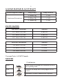
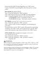
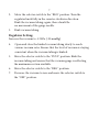
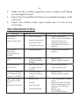
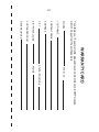
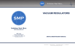
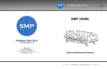
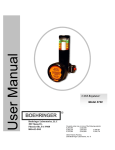
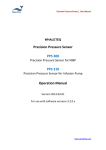
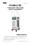
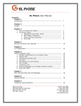
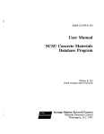
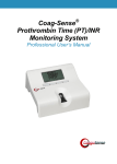
SECONDARY MEDICAL PRODUCTS
Solutions Start Here
VACUUM REGULATORS
Operating and Maintenance Instructions
V x x
-
x x x
-
x
-
x x
-
x
Gauge Direction
Shell Color
Mode
( I = Counter
(T = trap)
(Y = yellow)
(I = Intermittent)
Clockwise)
(N = nipple)
(W = white)
(C = Continuous)
( U = Clockwise)
Adapter
Example
(XX = No Adapter)
VYI - 300 - U - DS - T
Color: Yellow shell color
Mode: Intermittent
Gauge Direction: 0 - 300 mmHg
Gauge Direction: Clockwise
Adapter: DISS adapter
Bottom Fitting: Trap
Gauge Range
(300 = 300mmHg)
(400 = 400mmHg)
(760 = 760mmHg)
(OH = OHMEDA)
(CH = CHEMETRON)
(JS = JAPANESE STANDARD)
(DN = GERMAN STANDARD)
(BS = BRITISH STANDARD)
(DS = DISS STANDARD)
* 0-400 mmHg only available in Counter
Clockwise gauge
CAUTION: Federal (USA & Canadian) law restricts this device to sell by
or on the order of a physician.
PLEASE READ THOROUGHLY AND FOLLOW DIRECTIONS CAREFULLY BEFORE
OPERATING EQUIPMENT
1
TABLE OF CONTENTS
SAFETY INSTRUCTIONS ................................................................................................. 1
RECEIVING INSPECTION ................................................................................................ 2
INTENDED USE .................................................................................................................. 2
EXPLANATION OF ABBREVIATIONS .......................................................................... 2
GAUGE RANGE & ACCURACY ..................................................................................... 3
FLOW RATES ...................................................................................................................... 3
MODES ................................................................................................................................. 3
OPERATING ENVIRONMENTAL CONDITIONS ...................................................... 4
OPERATING INSTRUCTIONS ......................................................................................... 4
PARTS DESCRIPTION ....................................................................................................... 8
ASSEMBLY & DISASSEMBLY INSTRUCTIONS ......................................................... 12
CLEANING INSTRUCTIONS ......................................................................................... 12
MAINTENANCE ............................................................................................................... 13
TROUBLESHOOTING ..................................................................................................... 14
OVERFLOW SAFETY TRAP ........................................................................................... 15
WARRANTY CARD ....................................................................................................... WC
IMPORTANT: SAFETY INSTRUCTIONS
This manual provides you with important information about the
Vacuum Regulators and should be read carefully to ensure the safe
and proper use of this product.
Read and understand all the safety and operating instructions
contained in this booklet before using this product. If you do not
understand these instructions, or have any questions, contact your
supervisor, dealer or SMP Canada before attempting to use the
device.
2
WARNING: Indicates a potentially hazardous situation, which
if not avoided, could result in death or serious
injury.
ATTENTION: Indicates a potentially hazardous situation, which
if not avoided, could result in minor or moderate
injury.
CAUTION:
Indicates a potentially hazardous situation, which
if not avoided, could result in property damage.
RECEIVING INSPECTION
Remove the SMP Canada Vacuum Regulator from the packaging and
inspect for damage. If there is any damage, DO NOT USE and
contact your supplier.
ATTENTION:
It is crucial to allow the product to remain in the original packaging
for 24 hours to adjust to room temperature before use.
INTENDED USE
The SMP Vacuum Regulator is intended to regulate a supplied
vacuum pressure to the user’s desired vacuum level. A gauge indicates the
level of the regulated vacuum, which is adjustable by a regulated knob.
DO NOT attempt to change, alter or modify the intended use of this
product.
EXPLANATION OF ABBREVIATIONS
Abbreviation
Explanation
Lpm
Liters Per Minute
mmHg
Millimeters of Mercury
inHg
Inches of Mercury
kPa
Kilopascal
3
GAUGE RANGE & ACCURACY
Vacuum Regulator Model
Continuous/Intermittent
Gauge Range
Gauge Accuracy
0-300mm Hg
± 1.6%
0-400mm Hg
± 1.6%
0-760mm Hg
± 1.6%
FLOW RATES
Flow Rates: Continuous
Standard
VYC-300 & VWC-300
0-60 LPM
VYC-400 & VWC-400
0-60 LPM
VYC-760 & VWC-760
0-60 LPM
Flow Rates: Intermittent
Standard
VYI-300 & VWI-300
0-8 LPM
VYI-400 & VWI-400
0-8 LPM
VYI-760 & VWI-760
0-8 LPM
Vacuum Ports: 1/8 NPT female
MODES
Continuous
REG:
Allows degree of vacuum to be adjusted by use of
the regulating knob.
OFF:
Suction is no longer on or being supplied to the
patient.
FULL:
Maximum vacuum is administered to patient.
4
Intermittent
REG:
Allows degree of vacuum to be adjusted by use of
the regulating knob.
OFF:
Suction is no longer on or being supplied to the
patient.
INT:
Presets at 16 seconds ON and 8 seconds OFF.
OPERATING ENVIRONMENTAL CONDITIONS
Operating Environmental Limits:
Maximum 122ºF (50ºC) and Minimum 0ºF (-18ºC).
Recommended Environmental Operating Limits:
Maximum 84ºF (29ºC) and Minimum 55ºF (13ºC).
Storage Environmental Limits:
Maximum 140ºF (60ºC) and Minimum -4ºF (-20ºC).
Temperature Range:
Maximum 140ºF (60ºC) and Minimum -4ºF (-20ºC).
Humidity:
Max 95% Non condensing
OPERATING INSTRUCTIONS
CAUTION:
Inspect the vacuum regulator for visual damage before use, DO NOT
USE if there are any signs of damage on the product.
NOTE:
It is highly recommended to use Overflow protection with the
vacuum regulator (Safety trap, Bacteria filter, Canisters etc.)
5
Ensure that the SMP Vacuum Regulator is in “OFF” mode.
Connect the SMP Vacuum Regulator directly into the vacuum
outlet.
REG MODE (Regulated Mode)
Step 1: Turn the top knob to “REG” position.
Step 2: Block the bottom port of the SMP Vacuum Regulator.
Step 3: Using the Regulator Knob, set the desired Vacuum.
To INCREASE vacuum - Turn knob clockwise.
To DECREASE vacuum - Turn knob counter clockwise.
INT MODE *INTERMITTENT VACUUM REGULATOR ONLY
Step 1: Turn the top knob to “INT” position.
Step 2: Always verify vacuum setting prior to performing any
procedure.
Vacuum levels set in the “REG” mode will remain the same when
switched to the “INT” mode; and vacuum levels set in the “INT”
mode will remain the same when switched to the “REG” mode.
FULL MODE (Full, unregulated vacuum) *CONTINUOUS
VACUUM REGULATOR ONLY
Step 1: Turn the top knob to “FULL” position.
Step 2: Turn the top knob to “OFF” position to turn the
Regulator off.
WARNING:
When turning the Vacuum Regulator to “REG” from “INT”, “FULL” or “OFF”,
the vacuum level will return to its previously regulated setting. Vacuum may
be set at inappropriate level for procedure.
Always confirm vacuum setting prior to performing procedures. The vacuum
cannot be regulated when the top knob is set to “FULL” or “INT” position
depending on the type of vacuum regulator.
6
REG MODE
Turn selector knob fully clockwise to the regulator mode and
confirm vacuum setting before use.
FULL MODE
Turn selector knob fully counterclockwise for full vacuum and
confirm vacuum setting before use.
INT MODE
Turn selector knob fully counterclockwise for intermittent vacuum
and confirm vacuum setting before use.
Suction Tubing, which can be provided by SMP Canada, is required
between the patient port of the canister, as well as between the outlet
port of vacuum regulator and the collection jar. It is recommended
by SMP Canada to use 45 cm of tubing from SMP Canada Vacuum
Regulator to the collection jar and 180 cm of tubing from collection
jar to the patient. Quarter inch connection tubing is recommended by
NFPA.
Procedure Prior to Use List:
WARNING:
The following checklist is recommended prior to using this product
on each patient. If the vacuum regulator does not pass one or more
of the following tests outlined on the checklist, it should be inspected,
repaired and/or replaced by a qualified individual.
The following tests must be done with a minimum supply vacuum of
-53 kPa (-400mmHg):
1.
Move the selector switch to the “OFF” position. Turn the
regulator knob one complete turn in the clockwise direction.
Kink the vacuum tubing to block the
outlet. There should be no movement of the gauge needle.
7
2.
3.
Move the selector switch to the “REG” position. Turn the
regulator knob fully in the counter-clockwise direction.
Kink the vacuum tubing; again, there should be
no movement of the gauge needle.
Kink vacuum tubing.
Regulator Setting:
Increase the vacuum to -12 kPa (-90 mmHg)
4.
Open and close the kinked vacuum tubing slowly to reach
various vacuum rates. Ensure that the level of vacuum is staying
consistent when the vacuum tubing is kinked.
5.
Move the selector switch to the “FULL” position. Kink the
vacuum tubing and ensure that the vacuum gauge is reflecting
the maximum suction available.
6.
Move the selector switch to the “REG” position.
7.
Decrease the vacuum to zero and move the selector switch to
the “OFF” position.
8
PARTS DESCRIPTION
B
Continuous Vacuum Regulator
C
A
9
Continuous Vacuum Regulator
Item
Part No.
Description
Quantity
A
VRC-AFB
Back Body Set with Back Plate &
Steel screws
1
VRC-G400-CC
Gauge 0-400 mmHg
(Counter Clockwise)
with Positional Ring
VRC-G300-CW
Gauge 0-300 mmHg (Clockwise)
with Positional Ring
VRC-G300-CC
Gauge 0-300 mmHg
(Counter Clockwise)
with Positional Ring
VRC-G760-CW
Gauge 0-760 mmHg (Clockwise)
with Positional Ring
VRC-G760-CC
Gauge 0-760 mmHg
(Counter Clockwise)
with Positional Ring
VRC-EDW
Protective Case - White
with Flow Control Valve
VRC-EDY
Protective Case - Yellow
with Flow Control Valve
B
C
1
1
10
A
C
Intermittent Vacuum Regulator
B
D
E
11
Intermittent Vacuum Regulator
Item
Part No.
Description
Quantity
A
VRI-BBS
Back Body Set
1
VRI-G400-CC
Gauge 0-400 mmHg
(Counter Clockwise) with
Positional ring
VRI-G300-CW
Gauge 0-300 mmHg (Clockwise)
with
Positional ring
VRI-G300-CC
Gauge 0-300 mmHg
(Counter Clockwise) with
Positional ring
VRI-G760-CW
Gauge 0-760 mmHg (Clockwise)
with
Positional ring
VRI-G760-CC
Gauge 0-760 mmHg
(Counter Clockwise) with
Positional ring
VRI-FCV
Flow Control Valve
B
C
D
E
VRI-PCW
Protective Case - White
VRI-PCY
Protective Case - Yellow
VRI-DPL
Decorative Plate
1
1
1
1
12
ASSEMBLY & DISASSEMBLY INSTRUCTIONS
Continuous
A
Intermittent
B
C
Set
Set
A
B
C
D
E
Set
Set
Set
Set
Set
Set
Finished
Finished
CLEANING INSTRUCTIONS
1.
2.
Attach a working Vacuum Regulator with a continuous regulated
mode to a minimum vacuum source of 15 mmHg.
Mix cold disinfection/sterilization solution according to its
manufacturer’s directions.
13
3.
Connect tubing as shown in Cleaning Illustration on previous
page.
4. Turn the working Vacuum Regulator on to a continuous
regulated mode.
5. Adjust the vacuum to a minimum of 120 mmHg.
6. Set the Vacuum Regulator to be cleaned to the “REG” mode, and
set at 100 mmHg.
7. Allow cold disinfection/sterilization solution to pass through
and collect in Suction Canister. Procedure should continue for
time recommended by the manufacturer of the cold disinfection/
sterilization solution for the desired level of disinfection or
sterilization.
8. Turn the Vacuum Regulator to be cleaned to the “FULL ” mode
(if applicable).
9. Allow remaining cold disinfection/sterilization solution to pass
through and collect in Suction Canister.
10. Set working Vacuum Regulator to its maximum vacuum setting.
11. Thoroughly dry the internal components by drawing maximum
vacuum through the Regulator to be cleaned for at least 30
seconds in both “REG” and “LINE ” modes (if applicable).
NOTE:
If it is not possible to pass cold disinfection/sterilization solution
through the Regulator, then the passageways are totally blocked and
DISASSEMBLY of the Regulator is required. Be sure to follow your
facilities’ Biohazard protocol.
MAINTENANCE
The following are recommended maintenance steps that should be
taken after each patient:
1.
Clean the exterior of the Vacuum Regulator with a solution of a
diluted mild detergent.
14
2.
3.
4.
Make sure all secondary apparatus such as canisters and tubing
are thoroughly cleaned.
Inspect the bacteria filter. If it has been contaminated replace with
a new one.
Inspect the overflow safety trap to make sure it is free of any
restrictions.
TROUBLESHOOTING
Situation
No Vacuum at
Bottom port
(Gauge reading at 0)
Probable Causes of Situation
Manufacturer`s Recommendations
1.
Loose connection.
2.
Incorrect connection
1.
2.
to vacuum source.
3.
Tighten Connection.
Correct connector should be
used and connect to a
working vacuum source.
Disassemble and clean the
regulator.
3.
Clogged vacuum port.
No Vacuum at
Bottom port
(Gauge displaying
Vacuum)
1.
Clogged Regulator.
1.
Disassemble and clean the
regulator.
Gauge will not return
to 0
1.
2.
Gauge is damaged.
Regulator module is
damaged.
1.
2.
Replace gauge.
Replace regulator module.
Hard movement of
Selector Knob
1.
Dirty regulator module and/or selector
module.
1.
2.
Disassemble and clean.
Apply some lubricant.
Vacuum at bottom port
(No reading on gauge
when port is blocked)
1.
2.
Defective Gauge.
Damaged regulator
module.
1.
2.
Replace gauge.
Replace regulator module.
Under “REG” Mode
the regulator cannot
reach
specified suction level
1.
Low pressure.
1.
2.
Leakage.
2.
3.
Defective gauge.
4.
Clogged Regulator.
Check the pressure at vacuum
source.
Tighten all connections and
block the bottom port of the
regulator when adjusting
pressure.
Replace gauge.
Disassemble and clean.
3.
4.
15
Under “REG” Mode
the suction is too
strong and cannot be
reduced
1.
Damaged Regulator
Module.
1.
Replace Regulator Module.
Under “FULL” mode
the suction is not
reaching full capacity
1.
Low pressure.
1.
2.
Leakage.
2.
3.
Loose connection.
3.
Check the pressure at
vacuum source.
Check the pressure at zone
valve.
Tighten all connection and
block the bottom port when
reading the pressure.
1.
Timing circuit adjusted
incorrectly.
Damaged mode switch
O-Ring.
Clogged back plate
filter.
Damaged timing
assembly.
1.
Adjusting timing control.
2.
Replace O-Ring.
3.
Replace filter.
4.
Consult factory for service.
Fails to Cycle properly
in “INT” mode
2.
3.
4.
OVERFLOW SAFETY TRAP (Optional)
Purpose:
The SMP overflow safety trap serves an additional safe-guard to
protect vacuum regulating devices and central gas pipeline systems
from the accidental overflow of exudation from collection bottles.
16
Specification:
Bottle capacity: 80mL
WARNING & CAUTION FOR OPERATION
1.
2.
3.
4.
5.
Only personnel instructed and trained in its use should
operate this product.
Remove product from package and inspect for damage. Do not
use if there is any damage.
The product would only work with the Vacuum Regulator in a
vertical, upright position.
Be sure all connections are tight and leak free.
Do not use oil, grease, organic lubricants or any combustible
materials on or near this product.
Operation Instructions:
1.
2.
3.
4.
5.
6.
Verify that the float moves freely in the trap by turning it upside
down, and ensure the float drops back down to the very bottom
once tuned back.
Connect the Safety Trap onto the bottom of a Vacuum
Regulator. Screw the thread tightly.
Check the leakage by blocking the inlet port of the Safety Trap
and turning on the Vacuum Regulator to desired level. Check all
connections if the suction is not continuous.
Attach a suction system to the inlet port.
While excess exudation overflows into the trap during suction
procedure, the float will elevate, blocking the ports to stop the
suction.
To re-activate the suction, turn off the vacuum regulator first,
empty the trap, and re-install the system again.
17
Maintenance:
1.
2.
3.
4.
5.
6.
Detach the container and clean it thoroughly for next use. Clean
the cap with a cloth dampened with mild cleaning solution.
This product is autoclavable with high pressure saturated
steam at temperatures of 121°C for 10 mins.
This product can be sterilized with E.O. Gas.
Do not clean with aromatic hydrocarbons or sterilize with
Gamma Radiation.
Only qualified personnel should repair this product.
Unauthorized disassembly or attempt to repair will cause
damage to the product and void warranty.
Store the product in a clean area when not in use. Avoid
extreme temperatures or humidity.
Expiration:
8 years from date of manufacture, 5 years warranty.
WC
WARRANTY CARD
STATE / PROVINCE
SERIAL NO.
To validate your 5 year warranty, please fill out and mail this card to SMP Canada
within 10 days from the purchase date
MODEL
YOUR NAME
COMPANY NAME
CITY
PHONE
ADDRESS
ZIP / POSTAL CODE
PURCHASED FROM
DATE RECEIVED
Solutions Start Here
SECONDARY MEDICAL PRODUCTS
10 Sims Crescent
Richmond Hill, Ontario L4B 1K9, Canada
www.smpcanada.com
[email protected]
PLACE
FIRST
CLASS
POSTAGE