1
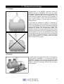
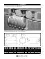
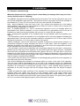
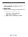
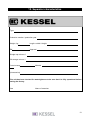
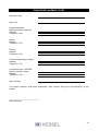
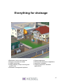
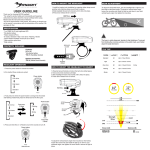
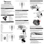
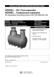
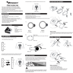
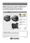
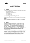
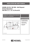
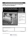
INSTALLATION AND OPERATING INSTRUCTIONS
KESSEL–Grease Separator Euro “G” NG 7-20
For underground installation
KESSEL Grease Separator Version G Art.Nos.
Certified under Euro-Norm EN 1825-1 93007/120(B/D)
NG 7 – 20 for underground installation 90010/120(B/D)
93015/120(B/D)
93020/120(B/D)
Product advantages
Euro-Norm 1825-1 certified
Quick and easy assembly
Compact / light
100% resistance against
aggressive grease and soil
acids
Transport friendly
Vertically adjustable upper
section
The installation and service of this unit should be carried
out by a licensed professional servicer
Company - Telephone No.
Edition 10/02-HG
ID number 010-615
(Subject to technical amendment
5.
Table of Contents
1. Safety precautions
Page 3
2. General
2.1 Application
Page 4
2.2 Separator description
Page 4
3. Transport and storage
3.1 Transport
Page 5
3.2 Storage
Page 5
4. Installation
4.1 Installation
Page 6
4.2 Drawing
Page 6
4.3. Separator commissionin
Page 7
5. Commissioning
5.1 Separator commissioning
Page 9
5.2 Commissioning participants
Page 9
6. Separator contents disposal
Page 10
7. Maintenance
Page 10
8. Replacement parts and accessories
Page 11
9. Guarantee
Page 12
10. Separator characteristics
Page 13
11. Important contacts / info
Page 14
2
1. Safety precautions
Dear Customer,
Before the KESSEL Euro Separator Version G is installed and placed in operation please
carefully read and follow all of the instructions contained in this Installation, Maintenance
and User’s Manual.
Upon delivery of the Euro Separator please thoroughly inspect the separator to make sure
that it has not been damaged during shipping. In case damage has occurred to the
separator, please follow the instructions listed in the ‚Guarantee‘ section of this user’s
manual.
By installation, use, maintenance and repair of this unit please follow all appropriate
DIN / VDE / DVGW safety precautions and accident prevention guidelines. Also please follow any
local safety precautions and accident prevention guidelines established in your area.
Please note that the unit is designed to receive kitchen waste water with a maximum temperature
of 60 degrees Celsius (140 degrees F). Temperatures higher than 60 degrees Celsius could
damage the unit.
________________________________________________________________________
Do not stand or place excessive weight on the separator. During disposal / emptying of a
Type G separator, a step ladder should be used to help gain access to the openings on the top of
the separator.
NO SMOKING! Smoking must not be permitted near the separator during use, maintenance and
repair of the unit due to the potential build up of methane / biogas.
SLIPPERY WHEN WET! Take caution when standing / walking near the separator.
During disposal, cleaning and maintenance the surrounding area can become extremely slippery
due to spilled water / grease / fat.
Separator Area Regulations:
No access of the separator for unauthorized personnel
No storage of food / groceries / provisions (for hygienic reasons) if the separator is installed
underground within a building.
The location of the separator should be chosen carefully as to allow sufficient access for
maintenance, inspection, repair and disposal of the separator.
The wastewater in a grease separator can contain bacteria. After coming in contact with
wastewater or the separator itself, it is important to wash, clean and disinfect all skin which has
been contaminated.
All personnel having anything to do with the separator should have a sound knowledge
of the above safety precautions.
3
2. General
2.1 Application
According to DIN 4040 and EN 1825, the installation of grease separators is required wherever oils
and fats from animals and plants are introduced into waster water systems. Uncollected, oils and
fats can cause serious damage to wastewater piping and private / public waste water treatment
plants.
2.2 Separator description
The KESSEL Euro Grease Separator Version G consist of a grease separator with integrated
sludge trap. The separator is constructed from Polyethylene (PE). Due to the smooth, wax like
surface of the material Polyethylene, no additional protective coating is necessary. The separator
is designed to be installed underground at a predetermined depth (below the frost level) and with
the selected load class manhole cover (Class A, B or D).
4
3. Transport and storage
3.1 Transport
Transportation of the KESSEL separator should be
handled only by a transporter who has the proper
knowledge, equipment and employees to handle such
a product. During transport the separator must be
firmly fixed into position and must not be allowed to
move or shift in place. It also must be protected from
other objects coming in contact with the separator
during transport.
If and when the separator is lifted it is important to
follow the following correct procedures: The separator
is not to be lifted with the use of steel cables or chains.
Proper equipment are heavy duty cloth or hemp straps
designed to handle the corresponding loads. The
separator should be lifted by placing the proper straps
beneath the inlet and outlet of the separator as seen in
the illustration. Do not lift the separator by the small
holes between the two manholes covers as illustrated
on this page. In instances where a forklift is used,
secure the separator to the forklift with appropriate
cloth / hemp securing straps.
3.2 Storage
In cases where the separator needs to be temporarily
stored before installation, it is important that the
separator is placed on firm level ground and in an area
where it is protected from coming in contact with other
objects. Storing the separator outdoors will not cause
any problems.
5
4. Installation
4.1 Installation illustration (class B, 12.5 tons)
4.2 Dimensioned drawing for NG 7, 10, 15 and 20 sizes
NG
7
10
15
20
DN
150
150
200
200
OD
160
160
200
200
L
B
Tmin
Tmax
2080
2860
2300
3060
1200
1200
1760
1760
950
950
1000
1000
1280
1280
1330
1330
H1
H2
1030
1030
1560
1560
1100
1100
1630
1630
Waste Water Content
Sludge Separator Fat
trap
volume
storage
700 l
1100 l
280 l
1000 l
1500 l
400 l
1500 l
3300 l
600 l
2000 l
3700 l
800 l
Weight
331 kg
403 kg
401 kg
473 kg
6
4. Installation
4.3. Separator commissioning
When the shipment arrives, please inspect it immediately for damage which may have been
caused during transport / shipping!
The KESSEL separator must be installed below the frost level. This can be achieved by the use of
the vertically adjustable upper sections. The manhole covers for the upper sections are available in
load classes A (1.5 ton), B (12.5 ton) and D (40.0 ton) and meet EN 124 standards.
Note - before installation, make sure that no dirt / grit / debris exits between any of the sealing
areas (gaskets). Also check the entire separator to make sure that no cracks, holes or dents have
occurred during transportation or storage.
Note - A standard KESSEL oil / fuel or coalescence separator is not to be installed below the
groundwater level. Before installation, be sure to determine the groundwater level at the site of
installation to make sure that groundwater will not come in contact with the separator.
Note - Underground separators to be installed below the groundwater table are available upon
request.
• The excavation in which the separator is to be installed must be level and capable of handling the
appropriate loads. The base of the excavation should be comprised of a 25 to 30 cm layer of frost
free gravel covered by a 3 to 10 cm layer of sand or fine gravel.
• Before installation, remove the float switch chamber (coalescence & float switch chamber if a
coalescence separator is being installed) and store in a safe place. Place the separator in the
prepared excavation hole. Make sure the separator is level and rests at the appropriate elevation.
Fill the separator with fresh cold water to the outlet level.
• The excavation should now be backfilled with non-binding material such as sand, or fine gravel.
Backfill only the main body of the separator, do not backfill around the upper sections. The backfill
should be firmly compacted at incremental levels (approx 300 mm). For load class D (40.0 ton)
situations, the upper section and manhole cover of the underground separator must be poured into
a steel reinforced concrete apron for proper load support. Additional information regarding this load
class D support is available from KESSEL.
• Connect the inlet and outlet of the separator to the drainage piping and fill the entire separator (to
the outlet level) with clean cold water.
• No vertical drainage pipes should be connected within one meter of the inlet of the separator.
This one meter section (immediately prior to the inlet of the separator) serves as a wastewater
calming section which hinders turbulence which can introduce unwanted oxygen and foam into the
separator. All connections of vertical pipe (outside of the 1 meter calming section) should me
connected to the main inlet pipe with two 45 degree fittings rather than one abrupt 90 degree
fitting.
• Install and adjust the upper section(s) of the separator to the desired level and secure with the
included clamp ring (clamp ring will rest on the chamber itself). Final upper section level
adjustments can be made by manipulating the elevation adjustment screws located on the clamp
ring. Back fill the remaining area around the upper sections with sand or fine gravel leaving space
for a 15 cm concrete load supporting apron (steel reinforced) if required.
7
4. Installation
NOTICE - Take care not to place any loads on top of the manhole covers and upper sections of the
separator until the separator is completely backfilled and (if required) the load supporting concrete
apron around the manhole covers has completely cured.
1) Sub-surface
gravel / process, compacted according to DIN 4226-1, Dp=95%
2) Support layer
compacted sand
3) Separator
KESSEL Separator
4) Excavation backfill gravel / process, compacted according to DIN 4226-1, Dp=95%
5) On-site material
unexcavated on-site material (leave in place)
6) Final layer
concrete, paving stones, earth etc.
8
5. Commissioning
5.1 Separator commissioning
Before the separator is put into service please make sure that:
The separator is completely clean, including inlet and outlet, and that the interior of the
chamber is free of dirt and debris.
The cleaned separator is completely filled with clean cold water up to the outlet.
5. 2 Commissioning participants
The commissioning of the separator is usually handled by a tradesman although this can be
handled by a KESSEL contractor or KESSEL employee if desired.
1) The following people should be on hand during the commissioning:
Building contractor representative
Plumber / tradesman who will be maintaining the separator
Building maintenance personnel
Disposal company who will be handling the disposal account
2) Commissioning preparation
Separator is completely filled with clean water
3) Commissioning
Separator to be checked for watertightness and for proper functionality
Contents of this user’s manuals to be discussed with those present
4) Transfer of this manual to the appropriate personnel
9
6. Separator contents disposal
The first emptying (disposal) of the separator contents should take place within 2 to 3 weeks from
the day the separator was placed into service.
Disposal intervals
According to DIN V 4040-2, it is advised that sludge and grease separators should be fully
emptied, cleaned and refilled with cold fresh water at fourteen day intervals or at least on a monthly
basis. In order for a grease separator to function as designed, it is very important that the separator
is emptied at regular intervals as described above. Due to this, it is recommended that a licensed
disposal company is contracted to empty the separator at regular intervals and during times when
strong odours will not present a problem.
Disposal procedure
• Remove manhole cover.
• Place disposal truck’s suction hose inside separator and remove entire
contects of chamber.
• Rinse and clean interior walls of chamber. Remove coalgulated fat/oil and
debris.
• Refill chamber with cold clean water.
• Clean and grease all accessible seals. Replace seals if necessary.
• Replace cover(s) and secure with cover clamps.
7. Maintenance
Before the separator is placed into service and at regular intervals thereafter, it is important
that:
1. The interior and exterior walls of the separator are thoroughly cleaned and checked
for damage. Inlet and outlet equipment should also be checked.
2. All inspection and maintenance work should be logged into this user’s manual.
Information concerning each disposal should also be kept on record.
Please take care that:
• This Installation, Service and Maintenance Guide is kept in a safe location where it is always
available.
•The disposal of the separator is only carried out by a certified company.
• Safety precautions listed in this manual and all other relevant safety precautions are followed
at all times.
• Smoking IS NOT ALLOWED in the near proximity to the separator due to the potential build
up of methane / biogas.
10
8. Replacement parts and accessories
11
9. Guarantee
1. In the case that a KESSEL product is defective, KESSEL has the option of repairing or replacing
the product. If the product remains defective after the second attempt to repair or replace the
product or it is economically unfeasible to repair or replace the product, the customer the has the
right to cancel the order / contract or reduce payment accordingly. KESSEL must be notified
immediately in writing of defects in a product. In the case that the defect is not visible or difficult to
detect, KESSEL must be notified immediately in writing of the defect as soon as it is discovered. If
the product is repaired or replaced, the newly repaired or replaced product shall receive a new
warranty identical to that which the original (defective) product was granted. The term defective
product refers only to the product or part needing repair or replacement and not necessarily to the
entire product or unit. KESSEL products are warranted for a period of 24 months. This warranty
period begins on the day the product is shipped from KESSEL to its customer. The warranty only
applies to newly manufactured products. Additional information can be found in section 377 and
378 of the HGB.
2. Wear and tear on a product will not be considered a defect. Problems with products resulting
from improper installation, handling or maintenance will also not be considered a defect.
01.01.2002
12
10. Separator characteristics
Type
Production number / production year
Weight / kg
length x width X height
EN
Approval
Sludge trap volume / l
Oil storage volume / l
Control stamp
Material
(Accessories)
This unit has been checked for watertightness to be sure that it is fully operational before
leaving the factory.
Date
Name of examiner
13
Important contacts / Info
Separator Type
Day / Hour
Project description /
Building services supervisor
Address
Telephone / Fax
Builder
Address
Telephone / Fax
Planner
Address
Telephone / Fax
Contracted plumbing company
Address
Telephone / Fax
Commissioning no. KESSEL
System operator / owner
Address
Telephone / Fax
Other remarks
The system operator, and those responsible, were present during the commissioning of this
system.
______________________________
Place and Date
14
Everything for drainage
Backwater valves and cleanouts
Polymer and cast iron drains
Volatile liquid traps
Lifting stations, pumps, warning and
control units
Rainwater management systems
Grease separators
Oil/fuel and coalescence separators
Inspection chambers
Custom projects for industrial
applications
15