1
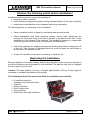
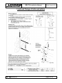
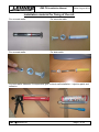
Installation Manual DELT Platform stairlift Web: www.lehner-lifttechnik.at Email: [email protected] Tel: +4372783514 Mobile: +436641612980 DELTA Installation Manual Edition August 2014 Table of content OBSERVE THE FOLLOWING POINTS BEFORE INSTALLATION! ........................................................................................................... 2 BEGINNING THE INSTALLATION ............................................................................................................................................................... 2 INSTALLATION OF THE RAILS ................................................................................................................................................................... 3 OVERVIEW PLATFORM COMPONENTS .................................................................................................................................................... 5 LOAD AND FIXINGS OF RAILS AND PILLARS .......................................................................................................................................... 5 INSTALLATION MATERIAL FOR FIXING OF THE RAIL: ........................................................................................................................... 7 INSTALLATION OF THE PLATFORM ONTO THE RAIL ............................................................................................................................. 8 INSTALLING OF THE CHARGING STATION/LIMIT ASSEMBLY ............................................................................................................. 10 ADJUSTING OF THE CONTROL CAMS.................................................................................................................................................... 11 LAST CHECKS BEFORE USING THE STAIRLIFT ................................................................................................................................... 12 TROUBLESHOOTING ................................................................................................................................................................................ 13 STANDARD ELECTRICAL COMPONENTS OF THE SIDEWALL ............................................................................................................ 15 ELECTRICAL COMPONENTS OF THE LOWER CARRIAGE ................................................................................................................... 16 OVERVIEW OF THE SWITCHBOARD LED FUNCTIONS ........................................................................................................................ 16 OVERVIEW OF THE PLATFORM MECHANICS........................................................................................................................................ 18 ADJUSTMENT OF THE PLATFORM INCLINATION ................................................................................................................................. 19 ADJUSTMENT OF THE LOADING RAMPS ............................................................................................................................................... 20 ADJUSTMENT OF MOTOR CURRENT ..................................................................................................................................................... 20 CONFIGURATION OF THE REMOTE RADIO CONTROLS ...................................................................................................................... 21 DISMANTLE THE PLATFORM FLOOR ..................................................................................................................................................... 23 ADJUSTMENT OF THE OVERLOAD SWITCH.......................................................................................................................................... 23 DELT platform lift page 1 of 24 DELTA Installation Manual Edition August 2014 Observe the following points before installation! Installation teams must have a general knowledge in: working on electric controls basic mechanical engineering and providing adequate fixation of the rails and pillars reading and understanding circuit diagrams and wiring schematics The following points are necessary for the installation: Have a complete tool kit on hand for mechanical and electrical works Check beforehand what fixing materials (screws, anchor bolts, adhesives) are required for the proper fixing of the rails to the wall or the pillars to the floor. These materials are not included in the delivery! The installation company is responsible for the fixing of the rail to the wall or the pillars to the floor/steps! Check the packages for shipping damage and missing parts before bringing the lift to the site. Take pictures of damaged parts as soon as these are discovered to provide proof for warranty claims. A team of 2 qualified technicians is necessary to install the lift. Beginning the Installation Bring the platform to the upper landing before fixing the rails in order to prevent damage to the rail and platform during transport on the staircase! The platform can only be engaged from the upper end of the rail. Caution: The large platform is heavy; it weighs approximately 120 kg. A dolly might be necessary to transport the platform up the steps. The following tools will be required to finish the installation successfully: A complete toolset for mechanical and electrical works Voltmeter Drilling machines Drills, thread cutter Fixing material Water lever with angle indication DELT platform lift page 2 of 24 DELTA Installation Manual Edition August 2014 Installation of the rails The rails can be fixed directly to the wall or on pillars that are fixed to the staircase. Upper cam Bracket Pillar Charging station and mechanical limit assembly Step 1: If there are 2 rail sections, combine both rail sections. See illustration. If there are more than 2 rail sections the 3rd rail sections has to be added once the first 2 are installed on the staircase. Step 2: Set the approximate angle between the rail and the bracket according to the angle given in the installation drawing. Then fasten all screws that connect the brackets to the upper and the lower rail. Fasten all screws that connect the brackets to the rail Use an anlge water level Upper rail Bracket DELT platform lift page 3 of 24 DELTA Installation Manual Edition August 2014 Step 3: First fix the upper bracket to the wall or to the upper pillar (pillars have the serial letters stamped on the base). The required dimensions for the first fixing point are given in the drawing – see dimension X1 and Y1 in example drawing below: Step 4: Adjust the correct angle of the rail. Now check the necessary clearance (dimensions D in illustration) between the lower rail and the step noses. In case the rail angle must be changed to get the correct clearance between rail and step then the angle of the lower platform carriage needs to be changed. Step 5: If the actual measurements correspond with the clearance dimensions on the layout drawing fix the remaining brackets to the walls or to the pillars. Step 6: Clean any debris from the rails. DELT platform lift page 4 of 24 DELTA Installation Manual Edition August 2014 Overview platform components DELT platform lift page 5 of 24 DELTA Installation Manual Edition August 2014 Load and fixings of rails and pillars DELT platform lift page 6 of 24 DELTA Installation Manual Edition August 2014 Installation material for fixing of the rail: For concrete walls: For concrete walls: For concrete walls: For brick walls: For brick walls: Adhesive 2 components glue for brick wall installation – injection pistol and adhesive DELT platform lift page 7 of 24 DELTA Installation Manual Edition August 2014 Installation of the platform onto the rail If you wish to reduce the weight of the complete unit, you can dismantle the platform floor from the carriage. Please see chapter “Changing the platform floor” for the detailed explanation. If you can manage to lift the platform with 2 or more people continue as outlined here below: Step 1: The upper charging station and the upper cam have to be removed from the rail Step 2: Dismantle the covers from the upper and lower carriages. The backside of the sidewall should look as shown on the picture beside. Step 3: Carefully lift the carriage on upper rail end, guiding the upper carriage rollers onto the upper rail. Then the lower carriage will be approached carefully to the lower rail. Step 4: Insert the hand wheel into the drive motor, loosen the break of the motor and turn the hand wheel into the downwards direction. Note: Always watch the interference of the tooth wheels (drive wheel and overspeed governor) and the rack. Have a look at the illustration to the right – if it does not go smoothly dismantle the platform again and insert it new! Do not use the motor for riding the carriage onto the rails! The tooth wheels of the drive and the overspeed governor can be damaged! Step 5: Install the batteries on the backside of the carriage (in case they have been removed). Check if the battery is connected correctly and switch on the main power switch. Step 6: Open the platform carefully so that the barrier arms and platform floor are horizontal. Now you can drive the platform further down by using the handset on spiral cable. DELT platform lift page 8 of 24 DELTA Installation Manual Edition August 2014 Step 7: Open the upper and lower frontal covers of the carriage. At delivery of the unit the upper carriage will be moveable (can rotate). This will facilitate the process of engaging the platform onto the rails. After engaging the platform the upper carriage has to be fastened – see below. Adjust the upper carriage to the same angle as the lower carriage and the rail. Note: After adjusting the angle of the upper carriage, fix the four nuts of the upper carriage. This must not be forgotten!!! Step 8: Run the carriage once up and down on the railway and check if the overspeed governor is adjusted well. There should be a constant gap between the rack and the guide holes in the overspeed governor. If not adjust the overspeed governor by loosening the fixing screw. Step 9: Reinstall the charging ramp and the clams for unblocking of the barrier arms to the upper end of the railway. Reinstall all covers on the carriages. Use this screw for fixing the overspeed governor Lever to trigger the overspeed governor DELT platform lift page 9 of 24 DELTA Installation Manual Edition August 2014 Installing of the charging station/limit assembly The position of the charging stations/limit assembly has to be adjusted so the limit switches on the lower carriages are pressed by the mechanical stop at the correct spot. Connect the stations according to the electric diagram. The positive connection goes to the charging ramps (copper material). The negative connection goes to the rail. Make sure there cannot be a short circuit between the copper and the rail. This could destroy the charger! Connect the upper and the lower copper charging ramp with a single phase cable. This cable can run behind the steel profile under the lower rail. Positive Negative Fix the charging station with the limit assembly onto the steel profile in the upper and lower landing. Fine adjust limit switches S27 and S28 if necessary with the slot hole under the carriage covers. Loosen screws and move plate up or Fine adjustment of the stop can be made by moving the limit switch fixing Fit the limit assemblies on the upper and lower landing to the steep plate The plastic buffers on the lower end of the backside of the carriage should touch down slightly on the bottom in the lower stop position. The lower limit assembly should be placed accordingly! In the upper stop position the platform should be in one line with the landing height, so the wheelchair driver can leave the platform horizontally, without any ramp inclination! Plastic buffers should just touch down on the bottom! Install the battery charger at any convenient place close to the upper or lower charging stations. Make sure there is no collision between the battery charger and the moving platform in case of wall fixing of the rail. DELT platform lift page 10 of 24 DELTA Installation Manual Edition August 2014 Adjusting of the control cams Adjust the control cams - the levers for unclamping the barrier must be in the middle of the control cams when the platform arrives in the stop position. Important: The charging lever must hit the charging ramps before the lever for unclamping of the barrier arms hit the control cams! Otherwise the lift would stop and can only be moved back by the hand wheel. The upper lever for unclamping is responsible for the left barrier and, the lower lever is responsible for the right barrier! Caution: Do not mount two control cams in the upper stop position! Else the lower barriere can be opened and the user may fall out of the platform!! Control cam Add the red colored plastic hood on the lever for the upper barrier – this indicates for the emergency rescue of passengers, as described in the user manual! If the control cams and the charging stations with the mechanical limits are correctly adjusted then the unit should be perfectly set for operation. In case the lift is not running perfectly there might further adjustments be necessary. Please check through the following pages. DELT platform lift page 11 of 24 DELTA Installation Manual Edition August 2014 Last checks before using the stairlift Before going into operation, check again the correct measurements and fixings and make sure there can be no collision between the platform and the staircase or any other obstacle. Make sure that the travel clearances are correct and all strut fasteners tightened. Caution: Do not ride on the unit until the fasteners are tightened. With the charging station, the limit blocks and the control cams in place, run the carriage up to the top of the system and back while checking the travel clearances of the carriage. When the landing is uneven and the loading ramp does not rest properly on the floor, adjust the ramps on the platform once more. Caution: The installation team is responsible for a proper carrying out of the installation. The unit has to be tested for secure working including its environment (structural influences)! Are there differences against the drawing, other influences or obvious defects which prevent a save working it is not allowed to set the lift into operation. If any malfunctions are occurring or adjustments need to be made please refer to the following pages for more detailed information. DELT platform lift page 12 of 24 DELTA Installation Manual Edition August 2014 Troubleshooting The platform is open and in or near a landing station and does not react at all If unit is near to a landing station use the hand wheel and move platform away from landing station so the lock barrier arm levers and the charging lever are both not pressed. If the lift then runs again check barrier cams position. If the unit is in the landing station, check the ultimate limit switch located under the carriage covers (which also activate the limit switch). If they are pressed drive back with the use of the hand wheel and prove the function of the limit switch If the platform is in a landing station check if the opposite limit switch is not pressed. If the upper limit switch S27 is pressed then LED 25 is off. If the lower limit switch S28 is pressed then LED 26 is off. Check if LED 24 is on. If not check barrier arm safety switches S14 and S15 and the ultimate limit switches S22u and S22o The platform can open and close in landing station and can run with the platform open but can not run with the platform closed Check adjustment of switch S11o. This switch must be pressed when the platform is closed. If not pressed LED 12 is off. The platform can open and close in landing station and can run with the platform closed but not with the platform open Check adjustment of switch S11p. This switch must be pressed when the platform is open. If not pressed LED 13 is off. The platform (open or closed) is in the upper landing station and cannot drive down Check if the LED 26 is on. If not check that the following switches are not pressed: Lower limit switch S28 Safety bottom switches S17 Lower ramp switch S12 or S13 Lower lateral contact board switches (if there are any) The platform (open or closed) is in the lower landing station and cannot drive up Check if the LED 25 is on. If not check that the following switches are not pressed: Upper limit switch S27 Upper ramp switch S12 or S13 Upper lateral contact board switches (if there are any) DELT platform lift page 13 of 24 DELTA Installation Manual Edition August 2014 The platform is closed and does not react at all First use the hand wheel to wind it around 10cm upwards. If the unit is in the upper landing station wind it 10cm downwards with the hand wheel. Then try function again. If the unit still does not work open the platform manually by disconnecting the platform connection. Take off side wall plastic covers and check LEDs on the switchboard and position of switches. Check if LED 24 is on. If not check barrier arm safety switches S14 and S15 and the ultimate limit switches S22u and S22o When a button is pressed on the remote sender and there is no red LED activated on the switchboard then check the programming of the remotes. If the unit is in the landing station, check the ultimate limit switched located under the carriage covers that also activate the limit switch. If they are pressed drive back with the use of the hand wheel and try again If the platform is in a landing station check if the opposite limit switch is not pressed. If the upper limit switch S27 is pressed then LED 25 is off. If the lower limit switch S28 is pressed then LED 26 is off. If the platform still does not move at all check the battery voltage. It should be 12-13V while pressing a drive button. If voltage is too low please check if the output voltage of the charger is around 24V DC. Please disconnect the charger from the charging stations when you measure. If the voltage it not around 24V then the charger is damaged. If the platform folding movement stops or works only incrementally then please check the potentiometer R50 as described below. If the driving up of the platform along the rail stops or only works incrementally then please check the potentiometer R40 as described below. If the platform stopped around 20-30cm after driving out of a landings station then please check if the barrier arm safety switches S13 and S14 are free. If they are pressed please check the description below. DELT platform lift page 14 of 24 DELTA Installation Manual Edition August 2014 Standard electrical components of the sidewall Control board Platform closed switch Platform motor Barrier arm Platform horizontal open switchswitch Ramp switch Ramp switch Barrier arm safety switch Barrier arm safety switch Barrier arm open switch Safety bottom switches DELT platform lift page 15 of 24 DELTA Installation Manual Edition August 2014 Electrical components of the lower carriage Batteries Levers for unblocking of barrier arms Limit switch Overspeed switch Limit switch Ultimate limit switch Ultimate limit switch By-pass switch DELT platform lift page 16 of 24 DELTA Installation Manual Edition August 2014 Overview of the switchboard LED functions DELT platform lift page 17 of 24 DELTA Installation Manual Edition August 2014 Overview of the platform mechanics Switch for lateral contact bar Lateral contact bar Barrier arm linkage Ramp activation Unblocking of barrier arms Actuator slider Switch for lateral contact bar Central platform mechanism plate Ball bearing linkage Mechancial stop for folding of platform DELT platform lift Hook for barrier arms opening Ramp linkage Ring screw page 18 of 24 DELTA Installation Manual Edition August 2014 Adjustment of the platform inclination To adjust the platform horizontally, change the adjustment screws as shown in the picture. Check in loaded condition! Counter the adjusting screw with the counter nut after successful adjustment. Caution: Check if both adjusting screws are supporting the platform! After changing the platform inclination please check the platform mechanism: Adjustment Between the hook and the slider should be around 2mm gap. This can be adjusted by moving switch S11m. S11p must be properly pressed when platform is open (it must click when pressed). Otherwise adjust. S11m Barrier arm adjustment S11o must be pressed when platform is closed. Otherwise adjust. Between the main bearing and the platform sliding mechanism a minimum distance of 1-2mm must be given. This can be adjusted by changing the length of the ball bearing connection between the platform and the carriage. This is important so that mechanical force of the platform in an unfolded position is not directly carried forward to the mechanical parts inside the platform, but rather held by the adjusting screws! Slider S11o S11p If barrier arms are not horizontal open the screw shown in the illustration, adjust the barrier and lock the adjustment with the screw again. DELT platform lift Hook 1-2mm distance Necessary 2mm gap Main bearing Extend ball bearing page 19 of 24 DELTA Installation Manual Edition August 2014 Adjustment of the loading ramps Adjust the ramps to achieve a 45 ° angle between the platform and ramp when the barrier is in horizontal position. When the barrier is open, the ramp has to fit to the bottom of the landing area. Also fix the ring at an angle of around 45° to the side of the ramp and at a distance of around 2/3 inside the slot. This ensures best operation. Check the loading ramps for proper operation. In folded and unfolded position of the platform, the ramps are also used as safety pads. When fixing the ramp ensure that it still can be pushed in order to activate the safety switches S12 and S13. 2/3 of slot length 45° 45° Best location of screw in distance of around 2/3 of slot length and ring turned at 45° to ramp side Adjustment of motor current On the electronic board you can adjust the maximum current of the drive motor and the maximum current of the platform actuator. Adjusting the main motor: Start on the lower landing with the full load capacity on the platform and drive upwards. While driving upwards, turn the potentiometer (R40) to the right until the lift stops. Now the maximum current is reached. You have to turn back the potentiometer (R40) a little. Try several times to drive up with the full load and the lift shouldn’t stop. main motor (poti R40) platform actuator (poti R50) Adjusting the platform actuator While closing the platform with the landing control turn the potentiometer (R50) to the right until the actuator stops. You have to turn back the potentiometer (R50) a little. Close the platform again several times and the actuator shouldn’t stop. DELT platform lift page 20 of 24 DELTA Installation Manual Edition August 2014 Configuration of the remote radio controls 2 different systems are offered for the Delta system. Version Schmidiger: To programme the remotes the button S1 on the control board where the receiver is connected to has to be pressed until the LED on the receiver start to blink. Now the senders can be programmed. To programme a sender the up and down button on the sender have to be pressed simultaneously. Then the LED on the sender start to blink in orange for 2,5 second and then remains on in an orange light and then green light. Now the sender is programmed. Now the next sender can be programmed in the same way by pressing the 2 buttons simultaneously. To stop the programming mode the button S1 has to be pressed again and the action will be confirmed by the receiver by fast blinking of the LED. The remote radio controls have different LED status indications. The below status refers to the radio control model TX-OMDE-V-01: LED status Description Green light Radio signal ok and drive command is active Orange light Radio signal ok and platform is not driving or folding A reason can be that the platform is driven from the platform control or that a safety circuit is open in the electrical system. Red light Orange blinking Red blinking Green blinking DELT platform lift Radio signal is ok but the lift is not moved by the command. Radio signal is not ok – there is a disruption The batteries of the sender a weak and should be changed The sender was successfully connected to the receiver during programming page 21 of 24 DELTA Installation Manual Edition August 2014 Version TeleRadio: To programme the remotes the button S1 on the control board where the receiver is connected to has to be pressed for 1-6 seconds. After releasing the button S1 the receiver waits for 5 seconds that any button on the sender to programme is pressed for at least 2 seconds. After he receives the signal from the sender the receiver goes back into normal operation mode and the sender is saved. Then the next sender can be programmed in the same way. DELT platform lift page 22 of 24 DELTA Installation Manual Edition August 2014 Dismantle the platform floor Dismantle the ball bearing connection between sliding mechanism and platform Disconnect platform rod connection for sidewall Dismantle safety under-pan of the platform Disconnect spring inside platform floor. You might need to manually compress the spring in order to uninstall the connection. Make sure that the connection between the spring and the bearing is correctly put together afterwards. The connection metal parts have a slight bend. It is important for reassembly that they are put back in the same way. Disconnect the electrical wiring between the platform floor and the sidewall Disconnect fixing screw from the treaded pinhole of main platform hinge bearing Remove the main bearing pin and take off the platform floor Loosen ball bearing Disconnect platform rod Disconnect spring Bend in metal part Disconnect fixing screw and wiring DELT platform lift Take out main bearing pin Take out spring page 23 of 24 DELTA Installation Manual Edition August 2014 Adjustment of the overload switch If the unit is equipped with an overload device it is mounted at the lower right part of the sidewall. The platform with full load presses the spring washers and if the real load exceeds the rated load by around 25% then the switch is activates and departure from the landing stop position is blocked by the overload switch. In case the switch needs adjustment on site it is necessary to load the platform with the rated load +25% and then adjust the switch with the adjustment screw so that it just activates under this load condition. See below illustration for explanation: Adjustment screw Overload switch Overload switch Move switch with adjustment screw till it activates under full load capacity + 25% DELT platform lift page 24 of 24