1
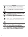
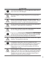
Main Unit
®
TR-57DCi
User’s Manual
Thank you for purchasing our product.
This manual provides a brief explanation
of how to set up and get started with the
TR-57DCi.
© Copyright T&D Corporation. All rights reserved.
2010.10 16504630002 (1st Edition)
Important Notices and Disclaimers
In order to properly use this product, please carefully read this manual before
using. T&D Corporation accepts no responsibility for any malfunction of and/or
trouble with this product or with your computer that is caused by the improper
handling of this product and will deem such trouble or malfunction as falling
outside the conditions for free repair outlined in the attached warranty.
- All rights of this User's Manual belong to T&D Corporation. It is prohibited to
use, duplicate and/or arrange a part or whole of this User's Manual without
the permission of T&D Corporation.
- Microsoft and Windows are registered trademarks of Microsoft Corporation in
the United States and/or other countries.
- Windows Vista is either a registered trademark or trademark of Microsoft
Corporation in the United States and/or other countries.
- All registered trademarks, company names, product names and logos
mentioned herein are the property of T&D Corporation or of their respective
owners.
- Specifications, design and other contents outlined in this manual are subject to
change without notice.
- Please follow the safety precautions outlined in this manual carefully. We
cannot guarantee nor are we responsible for safety if this product is used in
any manner other than was intended.
- On screen messages in this manual may vary slightly from the actual
messages.
- Please notify the shop where you purchased this product or T&D Corporation
of any mistakes, errors or unclear explanations in this manual. T&D Corporation
accepts no responsibility for any damage or loss of income caused by the use
of our product.
- This product has been designed for private or industrial use only. It is not for
use in situations where strict safety precautions are necessary such as in
connection with medical equipment, whether directly or indirectly.
- We are not responsible for any malfunction or trouble caused by the use of our
product or by any problem caused by the use of measurement results of our
unit. Please be fully aware of this before using our product.
- This User's Manual cannot be reissued, so please keep it in a safe place.
- Please read the warranty and provisions for free repair carefully.
Safety Precautions and Instructions
To ensure safety obey all of the following warnings.
The following items should be strictly obeyed for the safe usage of the
TR-57DCi Unit, (hereinafter referred to as this/the “Unit”) , and for
protecting yourself and other people from bodily harm and/or damage to
property. Before using this Unit, please read the following carefully and
fully understand the contents.
Explanation of Symbols
Explanation of Warning Symbols
DANGER
DANGER: These entries are actions that absolutely
under no circumstance should be taken. The taking of
such an action may cause serious personal physical
damage or death.
CAUTION
These entries are actions that if taken may lead to
physical injury or damage to persons or things.
Explanation of Picture Symbols
Denotes an important warning or caution. Specific warning
message is indicated by the symbol.
(EX: Caution against electric shock)
Denotes a forbidden action. Specific forbidden matter is
indicated inside or by the symbol.
(EX: Do not disassemble)
Denotes an action that must be taken. Specific instruction is
indicated inside or by the symbol.
(Ex: Unplug power plug from outlet)
1
DANGER
When installing and using this Unit, make sure to follow all
warnings and directions from your computer manufacturer.
Strictly Follow
Do not take apart, repair or modify the Unit. Doing so may
cause fire or electrocution.
Do Not
Disassemble
If water or a foreign object enters into the Unit, immediately turn
OFF the power, remove batteries, and stop using. Continued
Strictly Follow use may cause fire or electrocution.
Forbidden
Do not use this Unit in wet or humid places, such as a
bathroom. Doing so may cause fire, electrocution, and/or
malfunction.
Store the TR-57DCi Unit, batteries and communication cables
out of the reach of children. Touching them may cause injury
Strictly Follow and swallowing batteries is extremely dangerous.
Do not connect communication cables for the Unit to telephone
line outlets. Continued use may cause fire or electrocution.
Forbidden
Forbidden
Forbidden
2
If any smoke or strange smells are emitted from the Unit,
immediately turn OFF the power, remove batteries, and stop
using. Continued use may cause fire or electrocution.
Do not drop or expose the Unit to a strong impact. If that
happens to the Unit, immediately turn OFF the power, remove
batteries, and stop using. Continued use may cause fire or
electrocution.
CAUTION
This Unit is not waterproof. If the Unit gets dirty, wipe it with a
clean cloth and a mild detergent.
Strictly Follow
Do not put fingers or foreign objects into the communication
cable jack.
Forbidden
CAUTION
Battery life varies depending upon the type of battery, the
measuring environment, frequency of communication, ambient
temperature in which it is used, and battery performance.
Do not use any other batteries than those that are specified in
this Manual. It may cause fire or malfunction.
Forbidden
Do not use AC adaptors other than those specified for use with
the Unit. Doing so may cause fire or malfunction.
Forbidden
If the Unit is not to be used for a long period of time, for safety
reasons please remove the batteries. Leaving batteries inside
Strictly Follow the Unit may cause battery leakage and malfunction.
Battery terminals may provide insufficient contact due to age or
vibration. This may lead to data loss.
CAUTION
Condensation may occur if the Unit is moved from one
environment to another where the difference in temperature is
Strictly Follow great. Use this Unit in an environment where the ambient
temperature is from 0 to 50 and the humidity is 90%RH (no
condensation ) or less.
Forbidden
Harmful gases or chemicals may cause corrosion and/or other
danger to the Unit. Also, by coming into contact with hazardous
substances, harm may occur to the people handling the Unit.
Therefore, do not use or store it in any environment that is
exposed to chemicals and harmful gases.
3
To prevent damage to the Unit from static electricity, remove
static electricity from your body by touching metal around you
Strictly Follow (door knob, window frame) before touching the Unit. It may
cause data loss or damage to the Unit and data.
Forbidden
Do not use or store the Unit in any of the following places. Doing
so may cause electrocution, fire, and other adverse effects to
the Unit and/or your computer.
- Areas exposed to direct sunlight
This will cause the inside of the Unit to become overheated
and may cause fire, deformation, and/or other damage
including malfunction.
- Areas exposed to strong magnetic fields
This may cause damage including malfunction.
- Areas exposed to water leakage
This may cause electrocution or other damage including
malfunction.
- Areas exposed to static electricity
This may cause damage including malfunction.
- Areas exposed to excessive vibration
This may cause injury, malfunction, damage or loss of proper
electrical contact.
- Areas that are not flat or level
This may cause the Unit to fall and result in injury and/or
damage.
- Areas exposed to fire or overheating
This may cause damage including malfunction and deformation.
- Areas exposed to excessive dust and dirt
This may cause damage including malfunction.
4
Before Using this Product
Important Notes about the Installation Procedure
(for using USB communication)
In order to use a USB connection to communicate between the Unit and
a computer, it is necessary to install the software and the USB device
driver.
Before connecting the Unit to a computer with a USB communication
cable, it is necessary to first install the software and the USB device
driver. If you connect the Unit to the computer before installing them, the
USB device driver may not be installed properly.
If you have connected the Unit to your computer before installing the
USB device driver, make sure to click the [Cancel] button in the Wizard
window when it pops up on the computer display. Then disconnect the
USB communication cable from the Unit.
For more details about the proper installation procedure, see the
Software User’s Manual that accompanies “T&D Recorder for Windows”.
5
Table of Contents
Safety Precautions and Instructions------------------------------- 1
To ensure safety obey all of the following warnings. -----------------------1
Explanation of Symbols -----------------------------------------------------------1
Before Using this Product --------------------------------------------- 5
Important Notes about the Installation Procedure -------------------------5
Introduction
What is “Data Collector TR-57DCi”? ----------------------------- 10
Overview ---------------------------------------------------------------------------- 10
Basic Functions ------------------------------------------------------------------- 10
Package Contents ------------------------------------------------------ 12
Appearance Diagram and Part Names -------------------------- 13
Explanation of Button Functions ---------------------------------------------- 13
Using the Operation Dial -------------------------------------------------------- 14
LCD Display and Operation ---------------------------------------------------- 15
Getting Ready
Installing the Batteries------------------------------------------------ 18
About Battery Life ----------------------------------------------------------------- 18
Turning the Power On and OFF ------------------------------------ 19
Turn ON the Power --------------------------------------------------------------- 19
Turn OFF the Power -------------------------------------------------------------- 19
Auto Power Off Function -------------------------------------------------------- 19
Setting the Date and Time ------------------------------------------- 20
Communicating with the Computer ------------------------------ 21
USB Communication ------------------------------------------------------------- 21
RS-232C Serial Communication ---------------------------------------------- 22
Communicating with Data Loggers ------------------------------ 23
Optical Communication---------------------------------------------------------- 23
Cable Communication ----------------------------------------------------------- 23
Infrared Communication (limited to the downloading of data) --------- 23
Available Operations via Data Logger Communication ----------------- 24
6
Recording Settings for the Data Logger------------------------------------- 26
Introduction
Basic Functions
Recording Start --------------------------------------------------------- 26
Downloading Recorded Data --------------------------------------- 28
Downloading via Optical and Cable Communication -------------------- 28
Screen during Downloading---------------------------------------------------- 30
If Downloading Recorded Data Fails ----------------------------------------- 31
Graph Display------------------------------------------------------------ 32
Reading a Graph ------------------------------------------------------------------ 32
Upper and Lower Limit Judgment (RTR-500 Series only) -------------- 33
Getting Ready
Downloading via Infrared Communication ---------------------------------- 29
Event List Display ------------------------------------------------------ 34
Reading the Event List ---------------------------------------------------------- 34
Reading the Data List ------------------------------------------------------------ 37
Reading Data Details ------------------------------------------------------------ 38
Other Functions
Operational Settings -------------------------------------------------- 40
Basic Functions
Viewing Saved Data in Graph Form ------------------------------ 36
Changing Unit of Temperature ------------------------------------------------- 40
Adjusting the Backlight ---------------------------------------------------------- 40
Checking Memory ---------------------------------------------------------------- 41
Making Clock Settings ----------------------------------------------------------- 42
Muting the Operation Beep ----------------------------------------------------- 42
Checking Battery Voltage ------------------------------------------------------- 43
Deleting Data------------------------------------------------------------- 44
Other Functions
Adjusting Contrast ---------------------------------------------------------------- 41
Deleting Selected Data ---------------------------------------------------------- 44
Others
Menu List ------------------------------------------------------------------ 48
Others
Deleting All Data ------------------------------------------------------------------ 45
Specifications ----------------------------------------------------------- 50
Optional Accessories ------------------------------------------------- 51
7
8
Introduction
Introduction
Explanation of Product Outline for TR-57DCi
- What is “Data Collector TR-57DCi”?
- Package Contents
- Appearance Diagram and Part Names
9
What is “Data Collector TR-57DCi”?
Overview
The TR-57DCi is a device designed to collect recorded data from data
logger(s) already placed in the field. It is also possible to view collected
data and start recording on data loggers in areas where a computer is
not available.
Compatible Data Loggers
TR-74Ui/77Ui, TR-71U/72U/73U, TR-71S72S, TR-71/72, TR-51i/52i, TR51S/52S, TR-51A/52/51, VR-71, RTR-501/502/503/574*, RTR-51A/52A/53A*,
RVR-52A*, RTR-51/52/52Pt/53*, RVR-52*
* The TR-57DCi is not equipped with a wireless communication function.
Basic Functions
Easy Collection of a Variety of Data
The TR-57DCi can collect data from a wide variety of compatible data loggers.
Storage Capacity of 256,000 readings
One TR-57DCi has the capacity to store 16 units of TR-71U at full storage
capacity (8,000 readings x 2ch).When downloading units at non-full storage
capacity, it can store and manage up to 250 downloading sessions.
Collecting Recorded Data via Infrared Communication
The TR-57DCi can also use infrared communication to collect recorded data
from any of the TR-7Ui and TR-5i Series Data Loggers. Using infrared
communication releases the user from the burden of physically gathering the
loggers to collect data.
Graph Display on High Quality LCD
Collected data can be viewed immediately on the spot without the need for a
computer. The handy Operation Dial and buttons on the face of the Unit make it
possible to move the cursor as well as zoom in and out, thereby making the
checking of data a snap.
Handy Operation Dial for a Variety of Operations
Moving the Operation Dial up and down displays the various menu selections
which can be easily selected by pressing in on the dial.
Make Recording Condition Settings
10
From the TR-57DCi, it is possible to make settings, such as for “Recording Start
Date and Time”, “Recording Interval”, and “Recording Mode” for all compatible
data loggers except the VR-71.
When battery power becomes low, the Unit will automatically go into sleep mode
in order to protect the data. After going into sleep mode, the Unit can retain
recorded data for about a month.
Introduction
Backup Function
* All normal operations will stop in sleep mode, and it will become impossible to switch
ON the power of the Unit.
Battery Life Warning Display
When the battery power becomes low, a battery life warning mark will appear in
the Unit's LCD display.
About 100 Days of Battery Life with One Hour Daily Use
The expected battery life for two AAA alkaline batteries (LR03) is as follows:
used thirty minutes daily it should be about 160 days, used one hour daily it
should be about 100 days, used two hours daily it should be about 50 days. In
addition to AAA alkaline batteries, AAA Ni-Cd or AAA Ni-MH batteries (1.2V)
may also be used.
* Battery life varies depending upon the type of battery, the measuring environment,
the frequency of communication, and the ambient temperature in which it is used.
Specifications and explanations used in this User’s Manual are based on operations
carried out with a new battery and are in no way a guarantee of your actual battery
life.
Auto Power OFF Function
If the Unit is not used for about three minutes, it will automatically turn off to save
battery power.
Backlight Function
The LCD Backlight allows the display to be easily read even in the dark. You can
make changes in the Backlight ON/OFF by going to the [Main] Menu - [Set
Functions] - [Set Backlight].
* If the Unit is not used for more than five seconds, the LCD Backlight will automatically
turn off to save battery power. Once operation is re-started, it will automatically turn
back ON.
Firmware Update Function
The firmware can be easily updated by connecting the target TR-57DCi with a
USB communication cable to the computer. As newly compatible devices are
released, firmware updates will be periodically released to support these
changes. For more about how to update firmware and the latest update
information, visit our T&D website (http://www.tandd.com/).
11
Package Contents
The following items are included in the package:
Data Collector TR-57DCi x1
Software CD-ROM x1
(T&D Recorder for Windows TR-5,7xU (E))
USB Communication Cable
US-15C x1
(USB-A plug / USB mini-B plug)
RS-232C Communication Cable
TR-6C10 x1
(mini RS / mini RS)*
AAA Alkaline Battery x 2
TR-57DCi User’s Manual / Warranty
(this document) x 1
Software “T&D Recorder for Windows”
User's Manual x 1
* The mini-RS cable is used to connect T&D Data Collectors and Data Loggers.
12
1.
5.
8.
Introduction
Appearance Diagram and Part Names
6.
2.
7.
9.
3.
4.
5. USB Communication
1. Operation Dial
Cable Jack
2. LCD Display
6. RS-232C Communication
3. Operation Buttons
Cable Jack
4. Optical Communication
7. AC Adaptor Jack
Port
8. Infrared
Communication Port
9. Battery Cover
Explanation of Button Functions
- Press this to use infrared communication to start the
downloading of recorded data from a data logger.
- Press while viewing a graph to zoom out.
- Press while entire graph is on display to move cursor to the
lowest / highest value.
- Press to view the Data List Display.
- Press while viewing the Data List to view details for the data
on display.
- Press while viewing a graph to zoom in on data.
- Press to turn the power ON / OFF.
(for details see p.19)
13
Using the Operation Dial
Move the dial up
Press
Move the dial down
Moving the Dial Up and Down
- By moving the dial up and down, the arrow will move to allow you to choose the
desired item.
- When setting a numerical value, by moving the dial up the value will become larger,
and by moving the dial down the value will become smaller.
Pressing the Dial
- By pushing in on the dial, you can make a desired menu selection and complete or
activate a setting.
- If you press and hold while downloading recorded data or viewing a graph display,
you can change the channel on display.
14
Introduction
LCD Display and Operation
Main Menu Window
[
]
Menus for Infrared Communication
[
]
Menus for Optical or Cable Communication
[
]
When battery life goes low, a battery life
warning mark will appear to inform you it is
time to replace the battery. (See p.18)
[
]
An item marked with an arrow denotes it has
been selected. By moving the Operation Dial
up and down, the arrow will move accordingly.
By pressing the dial, the selected item will be
activated.
[ ][ ]
These indicate that there are more menu
items above or below for view. By moving the
Operation Dial up and down, you can scroll
the display.
[Back]
After making necessary settings, move the
arrow to [Back] and push the Operation Dial to
return to the Menu Window.
15
Recorded Data Displays
Graph Display
Temperature, Humidity, Barometric Pressure,
Illuminance, UV Light, Voltage, and Pulse Data
that have been downloaded to a TR-57DCi
can be displayed in graph form.
See p.32 for details about the display.
Event List Display
Event Data that has been recorded by an
RTR-52/52A and downloaded to a TR-57DCi
can be displayed in the Event List.
See p.34 for details about the display.
16
Getting Ready
This section explains what needs to be done to get a
TR-57DCi ready for use.
- Turning the Power On and OFF
- Setting the Date and Time
- Communicating with the Computer
Getting Ready
- Installing the Batteries
- Communicating with Data Loggers
17
Installing the Batteries
Insert two AAA alkaline batteries as shown below. (AAA Ni-Cd or
AAA Ni-MH batteries (1.2V) may also be used.
NOTE:
- Always use two batteries of the same type.
- Make sure not to mistake + / -.
- The TR-57DCi cannot recharge batteries.
About Battery Life
When battery life goes low, a battery life warning mark will be displayed
to inform you it is time to replace the battery. If battery life goes even
lower, the Unit will automatically go into sleep mode in order to save
data.
NOTE:
- In sleep mode, the Unit cannot be turned on or operated as usual.
- When replacing the battery, if the battery has been removed for more than five minutes, the
data stored in the Unit may be erased. It is recommended to first download any necessary
recorded data to your computer before replacing the battery.
- Also, you will lose all data if the battery drains completely; make sure to replace the battery as
soon as possible.
Battery Life Warning Mark
18
Turning the Power On and OFF
Turn ON the Power
Press the <ON/OFF> button or the Operation Dial to turn on the power.
Press the Operation Dial
Getting Ready
Press the <ON/OFF> Button
Turn OFF the Power
Press the <ON/OFF> to turn off the power. Turning off the power cannot
be carried out from the Operation Dial.
NOTE:
During communication, the power cannot be turned off even by pressing the <ON/OFF> button.
Auto Power Off Function
If the Unit is not in use for three minutes, the power will be automatically
switched off in order to save battery power.
19
Setting the Date and Time
Follow the procedure below to make clock settings for the TR-57DCi
Unit.
1. In the Main Menu, go to [Set Functions] and select [Set Clock].
2. Set the desired values.
(1) Moving the Operation Dial up and down will
change the selection item of the display in
the order of month, day, year, hour, and
minute. By pressing the dial, the value for
that item will flash.
(2) Change the value by moving the dial up and
down. Press the dial again to set the selected
value and move to the next settings item.
3. After having completed the clock settings, move the arrow to [Back] and
press the dial to return to the Menu Window.
[Time Zone]
By setting the region in which the TR-57DCi will be used the time difference will
be automatically set. Daylight Savings Time settings must be set manually.
NOTE:
- Please make sure that the date and time settings in the TR-57DCi are correct, if they are not,
the recording start time and recording time of downloaded data will be incorrect.
- Clock settings for the TR-57DCi can also be made from your computer by using the software
supplied with the Unit. For more details, see the [Help] Menu in the supplied software or the
User’s Manual that accompanies it.
20
Communicating with the Computer
To use a PC to download recorded data or make setting changes for
the data logger it is necessary to use a USB communication cable
US-15C (provided) or a communication cable RS-232C (optional) to
connect the TR-57DCi to your computer.
USB Communication
NOTE:
- Make sure the supplied software "T&D Recorder for Windows” has been installed before
connecting a TR-57DCi Unit to your PC.
- The USB device driver must be installed before trying to carry out USB communication. After
installing the USB device driver, your computer will be able to detect and recognize any
TR-57DCi Unit that is connected with a USB communication cable. Refer to the “Installing the
USB Driver” section in the “T&D Recorder for Windows User’s Manual” for the installation
instructions.
- When connecting a TR-57DCi to a PC, connect only one unit at a time. If you connect multiple
TR-57DCi Units at the same time, they may not be recognized properly.
- Make sure that the communication cable is completely inserted into the correct jack.
USB mini-B plug
To TR-57DCi
Getting Ready
For TR-57DCi <-> PC Communication
USB A plug
To PC
USB communication cable
US-15C
USB Port Mark
The USB communication cable is a USB-A plug <-> USB
mini-B plug. Connect the USB-A plug end of the cable into a
jack with a mark as shown at left.
21
RS-232C Serial Communication
For TR-57DCi <-> PC Communication
Use an optional RS-232C serial communication cable (TR-07C) to connect the
TR-57DCi to a serial port on your PC.
To TR-57DCi
D-Sub9 Pin Female
To PC
RS-232C Communication Cable
TR-07C (Option)
RS-232C Serial Port Symbols
The communication cable connector is a
D-Sub 9 pin female. Connect it to jack with
a mark shown at left.
22
Communicating with Data Loggers
There are three ways to communicate between a TR-57DCi and a
Data Logger: Optical Communication, Cable Communication, and
Infrared Communication. The communication method you select will
depend upon the type of Data Logger and the installation
environment.
For TR-5 / 5S / 5i Series and RTR-5 / 500 Series Data Loggers
Place the target logger face down on TR-57DCi.
TR-51i/52i, TR-51S/52S, TR-51A/51/52
RTR-501/502/503, RTR-51/51A/52/52A/52Pt/53/53A, RVR-52/52A
Getting Ready
Optical Communication
TR-57DCi Optical
Communication
Port
Cable Communication
For TR-7 Series, RTR-574, and VR-71 Data Loggers
Connect using the supplied
communication cable TR-6C10
TR-74Ui/77Ui,
TR-71U/72U/73U, RTR-574
Connect using the optional
communication cable TR-4C10
TR-71S/72S, VR-71
Infrared Communication (limited to the downloading of data)
For TR-7Ui / 5i Series Data Loggers
Place the infrared port of the TR-57DCi and the target Data Logger face-to-face.
TR-7Ui:About 5 to 20 cm
TR-5i:About 10 to 20 cm
Infrared Port of
TR-57DCi
Infrared Port of
Data Logger
TR-74Ui/77Ui, TR-51i/52i
23
Available Operations via Data Logger Communication
[Set Recording Conditions]
Recording settings can be made such as “Recording Mode”, “Recording
Interval”, and “Recording Start Date and Time (Programmed Start)”.
[Read Settings]
The TR-57DCi can read and display all settings for the connected Data Logger.
[Download Recorded Data]
The TR-57DCi can collect recorded data from the Data Logger.
* Infrared Communication can be used only to download recorded data.
24
Basic Functions
This section explains the basic operations and functions of
the TR-57DCi.
- Recording Start
- Downloading Recorded Data
- Graph Display
- Event List Display
- Viewing Saved Data in Graph Form
Basic Functions
25
Recording Start
Recording Settings for the Data Logger
The following settings and changes can be made from the TR-57DCi
Unit via Optical and Cable Communication.
- Recording Start
- Interval (Recording Interval)
- Recording Mode
NOTE:
Once the recording settings have been transmitted to the data logger, all previously recorded data
in the logger will be erased. It is recommended that you download and save necessary recorded
data before making or changing recording settings.
1. Connect the Data Logger to a TR-57DCi Unit.(See p.23)
2. In the Main Menu, open [
Record Settings].
3. Make the necessary recording condition settings.
* For details about the setting items, see the next page.
Main Menu
Record Settings Window
4. After having made the desired settings, adjust the arrow to [Execute]
and press the Operation Dial to transmit the recording settings to the
Data Logger.
5. Once the transmission has been completed, a message will appear on
the display to inform you that communication was completed
successfully. By pressing the Operation Dial you can go back to the
Main Menu.
26
[Immediate Start / Programmed Start]
After having completed the recording settings, make settings for recording start
date and time. First, make sure that the clock settings in the TR-57DCi are
correct (See p.20). Also, make sure to download all necessary recorded data
before executing any new recording start settings.
Immediate Start:
Recording conditions will be transmitted to the Data Logger and
recording will start immediately.
Programmed
Start:
Set the specific date and time for the Data Logger to start recording.
Programming the Date and Time to Start Recording
(1) Moving the Operation Dial up and down will
change the selection item of the display in the
order of month, day, year, hour, and minute. By
pressing the dial, the value for that item will
flash.
[Interval (Recording Interval)]
Select from one of the following 15 choices. Move the Operation Dial up and
down to choose the value, and press the dial to confirm it.
Basic Functions
(2) Change the value by moving the dial up and
down. Press the dial again to set the selected
value and move to the next settings item.
- 1, 2, 5, 10, 15, 20, or 30 seconds
- 1, 2, 5, 10, 15, 20, 30 or 60 minutes
* Recording interval settings cannot be made for event recording.
[Recording Mode]
Move the Operation Dial up and down to choose the recording mode, and press
the dial to confirm it.
One-Time
Endless
:
:
Recording will stop when the storage capacity becomes full.
Overwrite the oldest data when capacity is full.
27
Downloading Recorded Data
Use this to download recorded data from Data Loggers to the
TR-57DCi.
Downloading via Optical and Cable Communication
1. Connect the Data Logger to the TR-57DCi. (See p.23)
2. In the Main Menu, open [
Gather Data] to start downloading.
When downloading from a TR-51i / 52i you can select the period (how many
hours or days before now) from which you wish to download data. After the
selection is made, adjust the arrow to [Execute] and press the Operation Dial
to start downloading recorded data.
* If you wish to stop downloading, press the dial again.
3. A graph will appear showing the downloaded data.
If you have made Upper / Lower Limits settings for any RTR-500 Series
Remote Unit before downloading, the result will be displayed when the
downloading is completed. (See p.33)
28
Downloading via Infrared Communication
1. In the Main Menu, open [
Gather Data] or press the < Ir>button
on the TR-57DCi Unit.
2. Under [Sel.Logger], select the Data Logger Series from which you wish
to download data.
Basic Functions
For the TR-74Ui / 77Ui, select “TR-7i”. For TR-51i / 52i, select “TR-5i” and
specify the period of data to be downloaded.
* When using the < Ir>button to download data, this window will not appear and
communication will be carried out according to the same settings as the previous session.
3. After adjusting the arrow to [Execute] and pressing the Operation Dial,
place the infrared port of TR-57DCi and data logger face-to-face. (See
p.23)
29
4. Once a response from the target data logger is confirmed, the
downloading will start automatically.
Waiting for Response
Downloading Recorded Data
* If you wish to stop downloading, press the dial again.
5. The downloaded recorded data can be viewed in graph form.
If you have made Upper / Lower Limits settings for any RTR-500 Series
Remote Unit before downloading, the result will be displayed when the
downloading is completed. (See p.33)
Screen during Downloading
As data is being downloaded, a changing graph and the high and low
values for the received data will be continually shown. If you press and
hold down the Operation Dial while downloading recorded data you can
change the channel on display.
Press in Operation Dial while Downloading
Highest
Value
Lowest
Value
30
If Downloading Recorded Data Fails
Check the following:
Is there enough memory left in the TR-57DCi for the data?
If there is not enough memory remaining, the message [Memory Over] will
appear and downloading will stop. Please save recorded data from the TR-57DCi
to your PC and delete unnecessary data from the TR-57DCi to make space for
downloading new data from the Data Logger.
- See p.41 for details about how to check for remaining memory capacity.
- See p.44 for details about deleting data.
If a target TR-7Ui or TR-5i Series Logger has not been set to “Permit" Infrared
Communication, it will be impossible to download recorded data via Infrared
Communication. Using the software “T&D Recorder for Windows” or “Illuminance
UV Recorder for Windows”, make the necessary settings to permit Infrared
Communication, and try downloading again.
Basic Functions
Has Infrared Communication been set to “Forbid”?
* For details about Infrared Communication Settings, see the Data Logger User’s
Manual or the [Help] Menu in the supplied software.
31
Graph Display
In this display you can view in graph form the recorded data collected by the TR-57DCi.
A graph is displayed for each channel of data and can be scrolled
left and right with the Operation Dial or by the buttons on the
TR-57DCi.
Reading a Graph
1.
4.
2.
5.
6.
7.
3.
1. Displayed Channel
If there are multiple channels of recorded data, you can change the channel on
display by holding in the Operation Dial (for about one second).
2. Cursor
By moving the Operation Dial, you can scroll the cursor left and right to view the
recording date and time and measurement for that point where the cursor is
positioned.
3. Recording Interval and Mode
The “Recording Interval” and “Recording Mode” for the displayed data are shown
here.
S: Seconds, M: Minutes,
: One Time,
: Endless
4. Measurement at Cursor Position
The corresponding measurement value is displayed for the date and time where
the cursor is positioned.
[°C/°F]: Temperature, [%RH]: Humidity, [hPa]: Barometric Pressure, [lx]:
Illuminance, [mW/cm2]: UV Light, [V]: Voltage, [P]: Pulse
: Pulse Rising (OFF -> ON),
: Pulse Falling (ON -> OFF)
5. Upper and Lower Limit (RTR-500 Series Data Loggers only)
If Upper and/or Lower Limits have been set in the Data Loggers these limits will
be shown using dotted lines.
32
6. Graph Display Range
From the entire range of recorded data this line shows the range of data
currently on display. You can use the< List> button on the TR-57DCi to zoom in
and the < Ir> button to zoom out on data.
7. Date and Time of Cursor Position
The date and time of the current cursor position are shown here.
Upper and Lower Limit Judgment (RTR-500 Series only)
Upper and/or Lower Limits are set when making Recording Start settings
from a PC. When downloading recorded data from Remote Units for
which Upper / Lower Limits have been set, the judgment result will be
displayed automatically upon completion of the downloading and at the
time of graph display.
Basic Functions
Upon Completion of Downloading
At Time of Graph Display
(shows for about 5 seconds)
Reading Judgment Results
Starting from CH1, the results will be displayed in rotation.
: No measurements were over the set limits.
: One or more measurements exceeded the Upper Limit.
: One or more measurements exceeded the Lower Limit.
: Measurements exceeded both the Upper and Lower Limits.
: Upper and Lower Limit Settings were not made.
33
Event List Display
When using TR-57DCi to collect event data from RVR-52/52A, all
data can be viewed in the event list.
Reading the Event List
2.
1.
3.
1.
,
These show that data exists outside of the current display area. By using the
Operation Dial or the < Ir> / < List> buttons on the TR-57DCi, it is possible to
scroll up and down to bring data into view.
2. Number of Readings
This shows what number record out of the total number of records is being
currently highlighted by the cursor. (The above diagram shows that the data
being highlighted is 5th record out of a total of 168.)
3. Arrows
: Rising Edge Data
: Falling Edge Data
: Both Rising and Falling within 1 second
34
Events within an input voltage range of 0 to 30V are measured for every
1 second and the time and date are recorded if any change, rising
(Lo->Hi) or falling (Hi->Lo), occurs and lasts for more than 1 second.
Example of Changes between Rising and Falling
Basic Functions
When Both Rising and Falling occur Within 1 Second
35
Viewing Saved Data in Graph Form
1. Select [Data List] in the Main Menu, or press the <
List> button on the
TR-57DCi.
2. From the Select Data display, choose the data you wish to view in a
graph by moving the Operation Dial up and down, and press dial to
confirm.
Main Menu
Select data
The selected data will be highlighted. See the next page for the details about
the Data List.
3. Click on [Display Graph] to view the Graph for the selected data.
To view event data, after opening [Data List] click on [Event List].
For Temperature, Humidity, Barometric Pressure, Illuminance, UV Light,
Voltage, and Pulse Data
For Event Data
36
Reading the Data List
The notation may differ slightly depending on the Data Logger being
used.
The notation may differ slightly depending
on the Data Logger being used.
TR-5/TR-5i/TR-5S Series: Channel Name
TR-7/7Ui Series: Channel Name (ch.1)
RTR-5/RTR-500 Series: Remote Unit Name
Device Name
Device Name:
Channel Name:
The Channel Name entered when Recording Condition Settings were made via
PC.
Remote Unit Name:
The Remote Unit Name entered for a RTR-5 / RTR-500 Series Data Logger when
Recording Condition Settings were made via PC.
Basic Functions
The device name of the Data Logger is shown here. TR-71U/71S will be shown
as “TR-71x”, and TR-72U/72S will be shown as “TR-72x".
37
Reading Data Details
By clicking on the < List> button in the Data List Display, the details of
that data can be viewed.
Device Name
Recording Interval /
Recording Mode
Channel Name or
Remote Unit Name
Downloaded Date/Time
Recording Start Date/Time
Recording Stop Date/Time
or Last Recording Date/Time
Number of
Readings
About Recording Interval / Recording Mode
The Recording Interval and Mode will be shown as below.
-
38
=Recording Interval: 2 seconds, Recording Mode: One-time
=Recording Interval: 30 minutes, Recording Mode: Endless
Other Functions
This section contains explanations about other operational
settings for the TR-57DCi, as well as, how to delete
recorded data.
- Operational Settings
- Deleting Data
Other Functions
39
Operational Settings
Changing Unit of Temperature
By changing the Unit of Temperature, the Recorded Data display in the
TR-57DCi and the LCD display on the target Remote Unit(s) for which
recording was started from the TR-57DCi will be also be changed to
reflect the new setting.
1. In the Main Menu, open [Set Functions] and [Set Temp Unit].
Current Setting
Select
2. Move the arrow to [°C] or [°F] and press the Operation Dial.
3. Move the arrow to and click on [Back] to return to the Main Menu.
Adjusting the Backlight
1. In the Main Menu, open [Set Functions] and [Set Backlight].
2. Move the Operation Dial up to make the light brighter and down to
make it darker.
3. Press the Operation Dial to return to the Main Menu.
40
Adjusting Contrast
1. In the Main Menu, open [Set Functions] and [Set Contrast].
2. Move the Operation Dial up to make the display darker and down to
make it lighter.
3. Press the Operation Dial to return to the Main Menu.
Checking Memory
1. In the Main Menu, open [Set Functions] and [Check Memory].
Other Functions
2. Press the Operation Dial to return to the Main Menu.
41
Making Clock Settings
1. In the Main Menu, open [Set Functions] and [Set Clock].
2. Select the item you wish to change and press the Operation Dial.
3. Move the Operation Dial up and down to adjust clock.
4. Move the arrow to and click [Back] to return to the Main Menu.
Muting the Operation Beep
1. In the Main Menu, open [Set Functions] and [Beep].
Current Setting
Select
2. Move the arrow to either [ON] or [OFF] and press the Operation Dial to
confirm.
3. Move the arrow to [Back] and press the dial to return to the Main Menu.
42
Checking Battery Voltage
1. In the Main Menu, open [Set Functions] and [Battery Voltage].
2. Press the Operation Dial to return to the Main Menu.
Battery Voltage:
When battery power depletes to about 2.30V, the battery life warning mark will
appear.
Other Functions
43
Deleting Data
Deleting Selected Data
1. In the Main Menu, open [Data List]. Select the data you wish to delete
and press the Operation Dial.
Main Menu
Select data
2. Move the arrow to [Select Delete] and press the Operation Dial.
3. A confirmation screen will appear. Select [Execute] to delete the
selected data or [Back] not to delete it, and press the Operation Dial.
4. Upon completion of deletion, it automatically returns to the data
selection display.
44
Deleting All Data
1. In the Main Menu, open [Set Functions] and [Clear Memory].
Main Menu
2. A confirmation screen will appear. Select [Execute] to delete the
selected data or [Back] not to delete it, and press the Operation Dial.
3. Upon completion of deletion, press the Operation Dial to return to the
Set Functions Menu.
Other Functions
45
46
Others
- Menu List
- Specifications
- Optional Accessories
Others
47
Menu List
Gather Data
Back
Execute
Upon completion of the download, a
graph will appear.
Select a Device
TR-7i
TR-5i
Specify Period of
Data to be
Downloaded*
* The period for download can only be specified for TR-5i Series Loggers.
Gather Data
Specify the period of data to be downloaded (TR-5i only)
Upon completion of the download, a graph will appear.
Recording Settings
Back
Execute
Send Recording Settings
Start
Immediate Start
Programmed Start
Interval
Differs depending on the
Device Type
REC Mode*
One-Time
Endless
'YY/MM/DD
XX:XX:XX
Set Starting Date and Time
(For Programmed Start only)
* For TR-71/72, only One-Time mode can be selected.
48
Data List
Back
Select Data with
Operation Dial
Back
Display Data in
Graph
(Press Operation Dial
to display Graph)
Back
Continue
Select Delete
Back
Execute
Set Functions
Back
Set Temp Unit
Back
°C
°F
Back
OFF, 1 to 100
Set Contrast
Back
0 to 100
Check Memory
Back
Display Memory Usage (%)
Clear Memory
Back
Execute
Set Clock
Back
Settings
Beep
Back
ON
OFF
Battery Voltage
Back
Display Battery Voltage (V)
Others
Set Backlight
49
Specifications
Compatible Devices
Storage Capacity
TR-74Ui, TR-77Ui, TR-71U, TR-72U, TR-73U, TR-71S, TR-72S, TR-71,
TR-72, TR-51i, TR-52i, TR-51S, TR-52S, TR-51, TR-51A, TR-52, VR-71,
RTR-501, RTR-502, RTR-503, RTR-574, RTR-51A, RTR-52A RTR-53A,
RVR-52A, RTR-51, RTR-52, RTR-52Pt, RTR-53, RVR-52
Up to 256,000 readings
16 units of TR-51i at full storage capacity (16,000 readings x 1ch)
16 units of TR-71U at full storage capacity (8,000 readings x 2ch)
10 units of TR-73U at full storage capacity (8,000 readings x 2ch)
7 units of TR-74Ui at full storage capacity (8,000 readings x 4ch)
When downloading units at non-full storage capacity, it can store and
manage up to 250 downloading sessions.
Functions
Downloading Recorded Data, Viewing Saved Data in Graph Form,
Recording Start Settings, Displaying Highest and Lowest Measurement
LCD Displayed Items
Operation Menu, Graph Display, Battery Life Warning Display, Calendar
and Clock, Contrast Adjustment, Backlight
Power
AAA Alkaline Battery (LR03) x 2
(AAA Ni-Cd batteries or AAA Ni-MH batteries (1.2V) may also be used.)
AC Adaptor (optional)
Battery Life
About 100 days at 1 hour of daily use
* Battery life varies depending upon the type of battery, the measuring
environment, the frequency of communication, and the ambient temperature
in which it is used.
Data Backup
About 1 month (Saved data will be erased if all battery power is lost.)
PC Communication
Interfaces
USB Communication
RS-232C Communication 19,200 bps
Data Logger
Communication
Interfaces
RS-232C Communication: 9,600 to 19,200 bps
Optical Communication: 2,400 to 19,200 bps
Infrared Communication
Communication Time
- Between PC and TR-57DCi
USB Communication (16,000 readings x 1ch): approx. 12 seconds
USB Communication (8,000 readings x 4ch): approx. 24 seconds
RS-232C Communication (16,000 readings x 1ch): approx. 22 seconds
RS-232C Communication (8,000 readings x 4ch): approx. 42 seconds
- TR-5i Series
Optical Communication (16,000 readings x 1ch): approx. 24 seconds Infrared
Communication (16,000 readings x 1ch): approx. 55 seconds
- TR-7Ui Series
Infrared Communication (8,000 readings x 2ch): approx. 55 seconds
Infrared Communication (8,000 readings x 4ch): approx. 77 seconds
- TR-5S Series
Optical Communication (16,000 readings x 1ch): approx. 24 seconds
50
Dimensions
H125mm x W58mm x D23.8mm (excluding protrusions)
Weight
About 110g (including two AAA batteries)
Operating Environment
Temperature: 0 to 50°C, Humidity: 90 RH or less (no condensation)
Accessories
US-15C (USB communication cable / USB-A plug<->USB mini-B plug) x 1
TR-6C10 (Serial communication cable / mini-RS<->mini-RS) x 1
AAA Alkaline Battery (LR03) x 2
User’s Manual (Warranty) x 1, Software (CD-ROM) x 1
Optional Accessories
RS-232C Communication Cable
[unit: mm]
1500
TR-07C
RS-232C Communication Cable
Cable Length: 1.0m (40 in)
Connector Type:
Specialized Connector D-sub9pin
TR-6C10
1000
Cable Length: 1.0m (40 in)
USB Communication Cable
[unit: mm]
US-15C
1500
Cable Length: about 1.5m (60in)
AC Adaptor
AD-0638
Input: AC100-240V
Output: DC6V 500mA
Frequency: 50/60Hz
Cable length: 1.85m (74in)
AD-0638-C
AD-0638 + Plug Adaptor
Plug Figuration: C
Others
Plug Figuration: A
51
52
For product information or questions contact us at:
817-1 Shimadachi, Matsumoto, Nagano, JAPAN 390-0852
Fax: +81-263-40-3152
E-mail: [email protected]
Website
http://www.tandd.com/
We have opened an English Website for your convenience. Here you can
find information about our company, news, products, upcoming events,
software and user's manual downloads, as well as, other support. Please
stop by and see what we have to offer.
Data Collector TR-57DCi User's Manual
Published by T&D Corporation (1st Edition)
© Copyright T&D Corporation. All rights reserved.
This is printed on recycled paper.