1
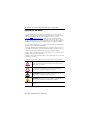
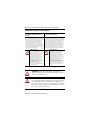
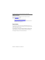
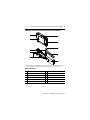
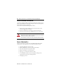
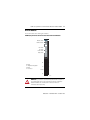
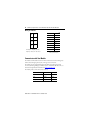
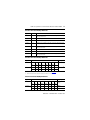
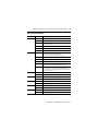
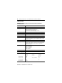
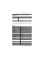
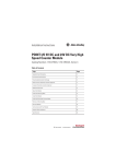
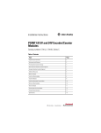
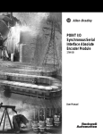
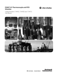
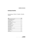
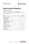
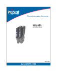
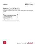
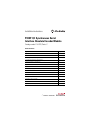
Installation Instructions
POINT I/O Synchronous Serial
Interface Absolute Encoder Module
Catalog number 1734-SSI, Series C
Table of Contents
Topic
Page
Important User Information
2
Environment and Enclosure
3
Preventing Electrostatic Discharge
3
North American Hazardous Location Approval
4
European Hazardous Location Approval
5
Additional Resources
6
About the Module
6
Install the Mounting Base
8
Install the Module
9
Install the Removable Terminal Block
10
Remove a Mounting Base
10
Wire the Modules
11
Communicate with Your Module
12
Interpret Status Indicators
14
Specifications
16
2 POINT I/O Synchronous Serial Interface Absolute Encoder Module
Important User Information
Solid-state equipment has operational characteristics differing from those of electromechanical
equipment. Safety Guidelines for the Application, Installation and Maintenance of Solid State Controls
(Publication SGI-1.1 available from your local Rockwell Automation sales office or online at
http://www.rockwellautomation.com/literature/) describes some important differences between
solid-state equipment and hard-wired electromechanical devices. Because of this difference, and also
because of the wide variety of uses for solid-state equipment, all persons responsible for applying this
equipment must satisfy themselves that each intended application of this equipment is acceptable.
In no event will Rockwell Automation, Inc. be responsible or liable for indirect or consequential damages
resulting from the use or application of this equipment.
The examples and diagrams in this manual are included solely for illustrative purposes. Because of the
many variables and requirements associated with any particular installation, Rockwell Automation, Inc.
cannot assume responsibility or liability for actual use based on the examples and diagrams.
No patent liability is assumed by Rockwell Automation, Inc. with respect to use of information, circuits,
equipment, or software described in this manual.
Reproduction of the contents of this manual, in whole or in part, without written permission of Rockwell
Automation, Inc., is prohibited.
Throughout this manual, when necessary, we use notes to make you aware of safety considerations.
WARNING: Identifies information about practices or circumstances that can cause an
explosion in a hazardous environment, which may lead to personal injury or death,
property damage, or economic loss.
ATTENTION: Identifies information about practices or circumstances that can lead to
personal injury or death, property damage, or economic loss. Attentions help you
identify a hazard, avoid a hazard and recognize the consequences.
SHOCK HAZARD: Labels may be on or inside the equipment (for example, drive or
motor) to alert people that dangerous voltage may be present.
BURN HAZARD: Labels may be on or inside the equipment (for example, drive or
motor) to alert people that surfaces may reach dangerous temperatures.
IMPORTANT
Identifies information that is critical for successful application and understanding of
the product.
Publication 1734-IN581E-EN-E - October 2015
POINT I/O Synchronous Serial Interface Absolute Encoder Module
3
Environment and Enclosure
ATTENTION: This equipment is intended for use in a Pollution Degree 2
industrial environment, in overvoltage Category II applications (as defined in IEC
60664-1), at altitudes up to 2000 m (6562 ft) without derating.
This equipment is not intended for use in residential environments and may not
provide adequate protection to radio communication services in such
environments.
This equipment is supplied as open-type equipment. It must be mounted within
an enclosure that is suitably designed for those specific environmental
conditions that will be present and appropriately designed to prevent personal
injury resulting from accessibility to live parts. The enclosure must have suitable
flame-retardant properties to prevent or minimize the spread of flame,
complying with a flame spread rating of 5VA or be approved for the application
if nonmetallic. The interior of the enclosure must be accessible only by the use
of a tool. Subsequent sections of this publication may contain additional
information regarding specific enclosure type ratings that are required to
comply with certain product safety certifications.
In addition to this publication, see:
• Industrial Automation Wiring and Grounding Guidelines, publication
1770-4.1, for additional installation requirements.
• NEMA Standard 250 and IEC 60529, as applicable, for explanations of the
degrees of protection provided by enclosures.
Preventing Electrostatic Discharge
ATTENTION: This equipment is sensitive to electrostatic discharge, which can
cause internal damage and affect normal operation. Follow these guidelines
when you handle this equipment:
•
•
•
•
•
•
Touch a grounded object to discharge potential static.
Wear an approved grounding wriststrap.
Do not touch connectors or pins on component boards.
Do not touch circuit components inside the equipment.
Use a static-safe workstation, if available.
Store the equipment in appropriate static-safe packaging when not in use.
Publication 1734-IN581E-EN-E - October 2015
4 POINT I/O Synchronous Serial Interface Absolute Encoder Module
North American Hazardous Location Approval
The following information applies when
operating this equipment in hazardous
locations:
Informations sur l'utilisation de cet équipement
en environnements dangereux:
Products marked "CL I, DIV 2, GP A, B, C, D" are suitable
for use in Class I Division 2 Groups A, B, C, D, Hazardous
Locations and nonhazardous locations only. Each product
is supplied with markings on the rating nameplate
indicating the hazardous location temperature code.
When combining products within a system, the most
adverse temperature code (lowest "T" number) may be
used to help determine the overall temperature code of
the system. Combinations of equipment in your system
are subject to investigation by the local Authority Having
Jurisdiction at the time of installation.
Les produits marqués "CL I, DIV 2, GP A, B, C, D" ne conviennent
qu'à une utilisation en environnements de Classe I Division 2
Groupes A, B, C, D dangereux et non dangereux. Chaque produit
est livré avec des marquages sur sa plaque d'identification qui
indiquent le code de température pour les environnements
dangereux. Lorsque plusieurs produits sont combinés dans un
système, le code de température le plus défavorable (code de
température le plus faible) peut être utilisé pour déterminer le
code de température global du système. Les combinaisons
d'équipements dans le système sont sujettes à inspection par
les autorités locales qualifiées au moment de l'installation.
EXPLOSION HAZARD
• Do not disconnect equipment unless
power has been removed or the area is
known to be nonhazardous.
• Do not disconnect connections to this
equipment unless power has been
removed or the area is known to be
nonhazardous. Secure any external
connections that mate to this equipment
by using screws, sliding latches,
threaded connectors, or other means
provided with this product.
• Substitution of components may impair
suitability for Class I, Division 2.
• If this product contains batteries, they
must only be changed in an area known
to be nonhazardous.
RISQUE D’EXPLOSION
• Couper le courant ou s'assurer que
l'environnement est classé non dangereux
avant de débrancher l'équipement.
• Couper le courant ou s'assurer que
l'environnement est classé non dangereux
avant de débrancher les connecteurs. Fixer
tous les connecteurs externes reliés à cet
équipement à l'aide de vis, loquets
coulissants, connecteurs filetés ou autres
moyens fournis avec ce produit.
• La substitution de composants peut rendre cet
équipement inadapté à une utilisation en
environnement de Classe I, Division 2.
• S'assurer que l'environnement est classé non
dangereux avant de changer les piles.
ATTENTION: To comply with UL restrictions, the secondary circuit
(backplane) must be powered from a source compliant with the following:
Class 2 or Limited Voltage/Current.
ATTENTION: This product is grounded through the DIN rail to chassis ground.
Use zinc plated yellow-chromate steel DIN rail to assure proper grounding. The
use of other DIN rail materials (for example, aluminum or plastic) that can
corrode, oxidize, or are poor conductors, can result in improper or intermittent
grounding. Secure DIN rail to mounting surface approximately every 200 mm
(7.8 in.) and use end-anchors appropriately.
Publication 1734-IN581E-EN-E - October 2015
POINT I/O Synchronous Serial Interface Absolute Encoder Module
5
European Hazardous Location Approval
The following applies when the product bears the Ex Marking
This equipment is intended for use in potentially explosive atmospheres as defined by
European Union Directive 94/9/EC.
DEMKO certifies that this equipment has been found to comply with the Essential Health
and Safety Requirements relating to the design and construction of Category 3 equipment
intended for use in Zone 2 potentially explosive atmospheres, given in Annex II to this
Directive.
Compliance with the Essential Health and Safety Requirements has been assured by
compliance with EN 60079-0:2012+A11:2013, EN 60079-15:2010, reference certificate
number DEMKO 04ATEX0330347X.
ATTENTION: This equipment is not resistant to sunlight or other sources of
UV radiation.
WARNING: This equipment shall be mounted in an ATEX certified enclosure
with a minimum ingress protection rating of at least IP54 (as defined in
IEC60529) and used in an environment of not more than Pollution Degree 2
(as defined in IEC 60664-1) when applied in Zone 2 environments. The
enclosure must utilize a tool removable cover or door.
WARNING: This equipment shall be used within its specified ratings defined
by Rockwell Automation.
WARNING: Provision shall be made to prevent the rated voltage from being
exceeded by transient disturbances of more than 140% of the rated voltage
when applied in Zone 2 environments.
WARNING: This equipment must be used only with ATEX certified Rockwell
Automation backplanes.
WARNING: Secure any external connections that mate to this equipment by
using screws, sliding latches, threaded connectors, or other means provided
with this product.
WARNING: Do not disconnect equipment unless power has been removed or
the area is known to be nonhazardous.
Publication 1734-IN581E-EN-E - October 2015
6 POINT I/O Synchronous Serial Interface Absolute Encoder Module
Additional Resources
Refer to POINT™ I/O 5V and 24V Encoder/Counter Modules User Manual,
publication 1734-UM006, as needed.
If you would like a manual, you can:
•
download a free electronic version from the internet:
http://www.rockwellautomation.com/literature/
•
purchase a printed manual by contacting your local Allen-Bradley distributor or
Rockwell Automation representative.
About the Module
You can use this Series C module with DeviceNet and PROFIBUS adapters. If you are
using RSLogix 5000 software, version 11 or higher, you can also use the Series C modules
with ControlNet and Ethernet adapters.
This module collects serial data from industrial absolute-position encoding sensors that
use standard SSI protocol. You insert the module into a POINT I/O terminal base that
provides common power, communication, and wiring connections for the SSI sensors.
Use this diagram to identify the external features of the module.
Publication 1734-IN581E-EN-E - October 2015
POINT I/O Synchronous Serial Interface Absolute Encoder Module
7
POINT I/O Synchronous Serial Interface Absolute Encoder Module
:
DE
NO
1
6
34
17 SI
S
2
7
8
3
4
9
5
10
The wiring base assembly includes a terminal base, 1734-TB or 1734-TBS, which consists
of a mounting base, 1734-MB, and removable terminal block, 1734-RT or 1734-RTS.
Module Description
Description
Description
1
Module locking mechanism
6
Slide-in writable label
2
Module Wiring Diagram
7
Insertable I/O module
3
DIN rail locking screw (orange)
8
Removable terminal block handle
4
Mechanical keying (orange)
9
Removable terminal block
5
Interlocking side pieces
10
Mounting base
Publication 1734-IN581E-EN-E - October 2015
8 POINT I/O Synchronous Serial Interface Absolute Encoder Module
Install the Mounting Base
To install the mounting base on the DIN rail, proceed as follows:
ATTENTION: This product is grounded through the DIN rail to chassis ground.
Use zinc plated yellow-chromate steel DIN rail to assure proper grounding. The
use of other DIN rail materials (for example, aluminum or plastic) that can
corrode, oxidize, or are poor conductors, can result in improper or intermittent
grounding. Secure DIN rail to mounting surface approximately every 200 mm
(7.8 in.) and use end-anchors appropriately.
1. Position the mounting base vertically above the installed units (adapter, power
supply or existing module).
2. Slide the mounting base down allowing the interlocking side pieces to engage the
adjacent module or adapter.
3. Press firmly to seat the mounting base on the DIN rail. The mounting base snaps
into place.
M
Stod
ule
atus
Ne
Stattwor
us k
NO
DE
:
0
24
So VDC
Ouurce
tput
1
2
3
17
OB34
4E
44013
4. To remove the mounting base from the DIN rail, remove the module and use a
small bladed screwdriver to rotate the base locking screw to a vertical position.
This releases the locking mechanism.
5. Then lift straight up to remove.
Publication 1734-IN581E-EN-E - October 2015
POINT I/O Synchronous Serial Interface Absolute Encoder Module
9
Install the Module
The module can be installed before or after base installation. Make sure that the mounting
base is correctly keyed before installing the module into the mounting base. In addition,
make sure the mounting base locking screw is positioned horizontal referenced to the base.
1. Using a bladed screwdriver, rotate the keyswitch on the mounting base clockwise
until the number required for the type of module being installed aligns with the
notch in the base.
Turn the keyswitch to align the number
with the notch. Position 3 is shown here.
44009
2. Make certain the DIN rail locking screw is in the horizontal position. You cannot
insert the module if the locking mechanism is unlocked.
Be sure the DIN rail locking screw
is in the horizontal position.
44010
M
Sta od
tu ule
s
3
1
O 73
B 4
4E
2
1
0
2
S 4V
O ou DC
utp rc
ut e
N
S e
N ta tw
O tu o
D s rk
E:
3. Insert the module straight down into the mounting base.
44012
4. Press to secure. The module locks into place.
Publication 1734-IN581E-EN-E - October 2015
10 POINT I/O Synchronous Serial Interface Absolute Encoder Module
Install the Removable Terminal Block
A removable terminal block (RTB) is supplied with your wiring base assembly. To remove,
pull up on the RTB handle. This allows the mounting base to be removed and replaced as
necessary without removing any of the wiring.
To reinsert the removable terminal block, proceed as follows:
1. Insert the end opposite the handle into the base unit. This end has a curved
section that engages with the wiring base.
2. Rotate the terminal block into the wiring base until it locks itself in place.
3. If an I/O module is installed, snap the RTB handle into place on the module.
WARNING: When you connect or disconnect the Removable Terminal Block
(RTB) with field side power applied, an electrical arc can occur. This could cause
an explosion in hazardous location installations.
Be sure that power is removed or the area is nonhazardous before proceeding.
Remove a Mounting Base
To remove a mounting base, you must remove any installed module, and the module
installed in the base to the right. Remove the removable terminal block, if wired.
1. Unlatch the RTB handle on the I/O module.
2. Pull on the RTB handle to remove the removable terminal block.
3. Press on the module lock on the top of the module.
4. Pull on the I/O module to remove from the base.
5. Repeat steps 1, 2, 3 and 4 for the module to the right.
6. Use a small bladed screwdriver to rotate the orange base locking screw to a
vertical position. This releases the locking mechanism.
7. Lift straight up to remove.
Publication 1734-IN581E-EN-E - October 2015
POINT I/O Synchronous Serial Interface Absolute Encoder Module
11
Wire the Modules
To wire the modules, refer to the diagrams and tables.
POINT I/O Synchronous Serial Interface Absolute Encoder Module
Module
Status
Module status
Network status
Network
Status
NODE:
RUN
Run status
Up status
Down status
Comp status
UP
DOWN
COMP
I1
1734
SSI
D = Data
I1 = Digital Sourcing Input 1
C = Clock
V = SSI Sensor
D+
D-
V+
V-
Shield
I1
C+
C43123
WARNING: If you connect or disconnect wiring while the field-side power is
on, an electrical arc can occur. This could cause an explosion in hazardous
location installations. Be sure that power is removed or the area is
nonhazardous before proceeding.
Publication 1734-IN581E-EN-E - October 2015
12 POINT I/O Synchronous Serial Interface Absolute Encoder Module
Wiring for 1734-SSI
0
Termination Definition(1)
1
D+
D-
2
3
V+
V-
4
5
Shield
I1
6
7
C+
C-
D = Data, I1 = Digital, Sourcing
Input 1, C = Clock, V = SSI Sensor
0
D+
1
D-
2
V+
3
V-
4
Shield
5
I1
6
C+
7
C-
(1)
D and C terminations are
RS422-type differential pairs.
Communicate with Your Module
The module transmits SSI sensor data over the DeviceNet network. You exchange data
with the master through a polled, cyclic, or change-of-state connection.
The module does not support Bit-Strobe Command Response Messaging and the
Unconnected Message Manager (UCMM). If you are not familiar with these terms, see
the DeviceNet Specification for definitions at http://www.odva.org.
The module produces and consumes data as follows:
I/O Connection Type
Consumes
Produces
Polled
2 bytes
10 bytes
Cyclic
2 bytes
10 bytes
Change-of-state
2 bytes
10 bytes
Publication 1734-IN581E-EN-E - October 2015
POINT I/O Synchronous Serial Interface Absolute Encoder Module
13
Consume and Produce Bit/Byte Definitions
Byte
Bit
Produce 0
0…7
Low byte of present low SSI word. Bit 0 is the least significant bit of the
entire present SSI word.
Produce 1
0…7
High byte of present low SSI word.
Produce 2
0…7
Low byte of present high SSI word.
Produce 3
0…7
High byte of present high SSI word. Bit 7 is the most significant bit of the
entire present SSI word.
Produce 4
0…7
Low byte of stored low SSI word. Bit 0 is the least significant bit of the
entire stored SSI word.
Produce 5
0…7
High byte of stored low SSI word.
Produce 6
0…7
Low byte of stored high SSI word.
Produce 7
0…7
High byte of stored high SSI word. Bit 7 is the most significant bit of the
entire stored SSI word.
Consume and Produce Bit/Byte Definitions
Byte
Bit
Produce 8
7
6
5
4
3
2
1
0
C2ST
C1ST
C2R
C1R
INC
DEC
RUN
I1
7
6
5
4
3
2
1
0
RES
RES
RES
LHON
IDF2
CCE
CCF
SPF
Produce 9
Description
(1)
For detailed descriptions of these bits, see 1734-SSI User Manual, publication 1734-UM009.
(2)
Monitor IDF to determine the validity of the produced data. If IDF=1, the SSI data is false.
Status byte 0(1)
Status byte 1(2)
Consume and Produce Bit/Byte Definitions
Byte
Bit
Consume 0
7
6
5
4
3
2
1
0
RES
RES
RES
SCMP2
SCMP1
CC2
CC1
LACK
7
6
5
4
3
2
1
0
RES
RES
RES
RES
RES
RES
RES
RES
Consume 1
(1)
Description
Master ACK
byte(1)
CONS1
The master must provide the master ACK byte to receive the polled produced bytes 0…9.
Publication 1734-IN581E-EN-E - October 2015
14 POINT I/O Synchronous Serial Interface Absolute Encoder Module
Interpret Status Indicators
Refer to the following diagram and tables for information on how to interpret the
status indicators.
POINT I/O Synchronous Serial Interface Absolute Encoder Module
Module
Status
Module status
Network status
Network
Status
NODE:
RUN
Run status
Up status
Down status
Comp status
UP
DOWN
COMP
I1
1734
SSI
43123
Publication 1734-IN581E-EN-E - October 2015
POINT I/O Synchronous Serial Interface Absolute Encoder Module
15
Indicator Status for Modules
Module status
Status
Description
Off
No power applied to device.
Green
Device operating normally.
Flashing green
Device needs commissioning due to missing, incomplete, or
incorrect configuration.
Flashing red
Recoverable fault.
Red
Unrecoverable fault – may require device replacement.
Flashing red/green Device is in self-test mode.
Network status Off
Device is not online:
- Device has not completed dup_MAC-id test.
- Device not powered – check module status indicator.
Flashing green
Device is online but has no connections in the established state.
Green
Device is online and has connections in the established state.
Flashing red
One or more I/O connections are in timed-out state.
Red
Critical link failure – failed communication device. Device detected
error that prevents it from communicating on the network.
Flashing red/green Communication faulted device – the device has detected a network
access error and is in communication faulted state. Device has
received and accepted an Identity Communication Faulted Request
– long protocol message.
Run status
Off
Module is commanded to stop retrieving SSI data.
Green
Module is commanded to retrieve SSI data.
Up status
Off
SSI data not increasing, or no SSI data is being received.
Green
SSI data is increasing.
Down status
Off
SSI data not decreasing, or no SSI data is being received.
Comp status
I1 status
Green
SSI data is decreasing.
Off
Comparator function is not in use, or comparator value not attained.
Green
Comparator value attained.
Off
Latching input I1 is OFF.
Green
Latching input I1 is ON.
Publication 1734-IN581E-EN-E - October 2015
16 POINT I/O Synchronous Serial Interface Absolute Encoder Module
Specifications
POINT I/O Synchronous Serial Interface Absolute Encoder Module –
1734-SSI, Series C
Attribute
Value
Number of SSI channels
1
Encoder type
Any absolute encoder supporting standard SSI protocol including linear,
rotary, and optical distance measuring devices
Most-Significant Bit Aligned data format
Physical interface for clock and data signals is RS-422
SSI data rate
125 kHz, 250 kHz, 500 kHz, 1 MHz, 2 MHz (software selectable)
SSI bits per word
2…31 (software selectable)
SSI word delay time(1)
16 μs…65535 μs (software selectable)
SSI word length
4 bytes (32 bits)
SSI features
Gray or binary code capable with gray to binary conversion, increasing or
decreasing SSI count indication, 2 SSI word comparator values, SSI word
latching with I1 input
SSI position forming time(2)
≥0.5 ms
SSI cable type
UL CM/AWM 2464/CSA Type CMG FT4 or similar cable utilizing shielded
twisted pairs for D+/- and C+/- connections. See sensor manufacturer for
actual cable required for the SSI sensor under use. I1 input can be
separate from SSI cable.
SSI cable length
Depends on desired SSI data rate:
125 kHz – 320 m (1050 ft)
250 kHz – 160 m (525 ft)
500 kHz – 60 m (195 ft)
1 MHz – 20 m (65 ft)
2 MHz – 8 m (25 ft)
SSI sensor power
450 mA, 10…28.8V DC
SSI clock drive current
(Out of C+/- terminals), max
125 mA
Input I1
IEC Type 3 voltage and current characteristics, sourcing type
Minimum
Nominal
Maximum
ON-state voltage
0V DC
-
FPV* -10
ON-state current
2 mA
4 mA (FPV=24V DC)
5 mA
OFF-state voltage
FPV-5
-
FPV
OFF-state current
1.2 mA
-
-
Publication 1734-IN581E-EN-E - October 2015
POINT I/O Synchronous Serial Interface Absolute Encoder Module
17
POINT I/O Synchronous Serial Interface Absolute Encoder Module –
1734-SSI, Series C
Attribute
Input impedance
Input filter time
Value
-
3.6 kΩ
4.7 kΩ
-
0.5 ms
-
*FPV = Field power supply voltage
(1)
Time between successive SSI words (Tp). Also called Dwell Time.
(2)
Roughly corresponds to the maximum time the SSI sensor can be expected to output a particular position value while in
motion. To use the 1734-SSI module with sensors that have faster position forming times, change the SSI Word Filter
Control parameter from its default value of 5 (max). Changing this parameter from its default value sacrifices electrical
noise environment performance for sensor data conversion speed.
General Specifications
Attribute
Value
Terminal base screw torque, max
0.6 Nm (7 lb-in.)
LED indicators
All powered from the logic side
Module location
1734-TB, 1734-TBS wiring base assembly
POINTBus current
110 mA @ 5V DC
Power dissipation
0.94 W
Isolation voltage
50V (continuous), Basic Insulation Type
Tested @ 1250V AC for 60 s, field to system
Field power bus supply voltage, min
10V DC @ 450 mA
Field power bus supply voltage, nom
24V DC @ 450 mA
Field power bus supply voltage, max
28.8V DC @ 450 mA
Dimensions, HxWxD
56.0 x 12.0 x 75.5 mm
(2.21 x 0.47 x 2.97 in.)
Conductor category(1)
1 – on signal ports
Wire size
0.34…2.1 mm2 (22…14 AWG) solid or stranded copper wire
rated @ 75 °C (167 °F), or greater, 1.2 mm (3/64 in.)
insulation max
Wire type
Copper
Shielded on encoder port
Weight
0.032 kg (0.07 lb)
Keyswitch position
2
Publication 1734-IN581E-EN-E - October 2015
18 POINT I/O Synchronous Serial Interface Absolute Encoder Module
General Specifications
Attribute
Value
Enclosure type rating
None (open-style)
North American temp code
T4A
IEC temperature code
T4
(1)
Use this conductor category information for planning conductor routing as described in Industrial Automation Wiring
and Grounding Guidelines, publication 1770-4.1.
Environmental Specifications
Attribute
Value
Temperature, operating
IEC 60068-2-1 (Test Ad, Operating Cold),
IEC 60068-2-2 (Test Bd, Operating Dry Heat),
IEC 60068-2-14 (Test Nb, Operating Thermal Shock):
-20…55 °C (-4…131 °F)
Temperature, surrounding air, max. 55 °C (131 °F)
Temperature, nonoperating
IEC 60068-2-1 (Test Ab, Unpackaged Nonoperating Cold),
IEC 60068-2-2 (Test Bb, Unpackaged Nonoperating Dry Heat),
IEC 60068-2-14 (Test Na, Unpackaged Nonoperating Thermal Shock):
-40…85 °C (-40…185 °F)
Relative humidity
IEC 60068-2-30 (Test Db, Unpackaged Damp Heat):
5…95% noncondensing
Vibration
IEC 60068-2-6 (Test Fc, Operating):
5 g @ 10…500 Hz
Shock, operating
IEC 60068-2-27 (Test Ea, Unpackaged Shock):
30 g
Shock, nonoperating
IEC 60068-2-27 (Test Ea, Unpackaged Shock):
50 g
Emissions
CISPR 11 (IEC 61000-6-4):
Class A
ESD immunity
IEC 61000-4-2:
6 kV contact discharges
8 kV air discharges
Radiated RF immunity
IEC 61000-4-3:
10V/m with 1 kHz sine-wave 80% AM from 80…2000 MHz
10V/m with 200 Hz 50% pulse 100% AM @ 900 MHz
10V/m 200 Hz 50% pulse 100% AM @ 1890 MHz
10V/m with 1 kHz sine-wave 80% AM from 2000…2700 MHz
Publication 1734-IN581E-EN-E - October 2015
POINT I/O Synchronous Serial Interface Absolute Encoder Module
19
Environmental Specifications
Attribute
Value
EFT/B immunity
IEC 61000-4-4:
±3 kV @ 5 kHz on signal ports
Surge transient immunity
IEC 61000-4-5:
±1 kV line-line (DM) and ±2 kV line-earth (CM) on signal ports
±2 kV line-earth (CM) on shielded ports
Conducted RF immunity
IEC61000-4-6:
10 V rms with 1 kHz sine-wave 80% AM from 150 kHz…80 MHz
Certifications
Certification (when
product is marked)(1)
Value
c-UL-us
UL Listed Industrial Control Equipment, certified for US and Canada. See
UL File E65584.
UL Listed for Class I, Division 2 Group A,B,C,D Hazardous Locations,
certified for U.S. and Canada. See UL File E194810.
CE
European Union 2004/108/EC EMC Directive, compliant with:
EN 61326-1; Meas./Control/Lab., Industrial Requirements
EN 61000-6-2; Industrial Immunity
EN 61000-6-4; Industrial Emissions
EN 61131-2; Programmable Controllers (Clause 8, Zone A & B)
C-Tick
Australian Radiocommunications Act, compliant with:
AS/NZS CISPR 11; Industrial Emissions
Ex
European Union 94/9/EC ATEX Directive, compliant with:
EN60079-15: 2010; Potentially Explosive Atmospheres, Protection "n"
EN60079-0:2012+A11: 2013; General Requirements
II 3 G Ex nA IIC T4 Gc
DEMKO 04 ATEX 0330347X
KC
Korean Registration of Broadcasting and Communications Equipment,
compliant with:
Article 58-2 of Radio Waves Act, Clause 3
(1)
See the Product Certification link at http://www.rockwellautomation.com/products/certification/ for Declaration of
Conformity, Certificates, and other certification details.
Publication 1734-IN581E-EN-E - October 2015
Rockwell Automation Support
Rockwell Automation provides technical information on the Web to assist you in using its products. At
http://www.rockwellautomation.com/support/, you can find technical manuals, a knowledge base of FAQs,
technical and application notes, sample code and links to software service packs, and a MySupport feature
that you can customize to make the best use of these tools.
For an additional level of technical phone support for installation, configuration and troubleshooting, we
offer TechConnect support programs. For more information, contact your local distributor or Rockwell
Automation representative, or visit http://www.rockwellautomation.com/support/.
Installation Assistance
If you experience a problem within the first 24 hours of installation, please review the information that's
contained in this manual. You can also contact a special Customer Support number for initial help in getting
your product up and running.
United States or Canada
1.440.646.3434
Outside United States or
Canada
Use the Worldwide Locator at
http://www.rockwellautomation.com/support/americas/phone_en.html, or
contact your local Rockwell Automation representative.
New Product Satisfaction Return
Rockwell Automation tests all of its products to ensure that they are fully operational when shipped from
the manufacturing facility. However, if your product is not functioning and needs to be returned, follow
these procedures.
United States
Contact your distributor. You must provide a Customer Support case number
(call the phone number above to obtain one) to your distributor to complete
the return process.
Outside United States
Please contact your local Rockwell Automation representative for the return
procedure.
Documentation Feedback
Your comments will help us serve your documentation needs better. If you have any suggestions on how to
improve this document, complete this form, publication RA-DU002, available at
http://www.rockwellautomation.com/literature/.
Allen-Bradley, Rockwell Automation, ArmorBlock, and TechConnect are trademarks of Rockwell Automation, Inc.
Trademarks not belonging to Rockwell Automation are property of their respective companies.
Publication 1734-IN581E-EN-E - October 2015
Supersedes Publication 1734-IN581D-EN-E - January 2014
Copyright © 2015 Rockwell Automation, Inc. All rights reserved.