1
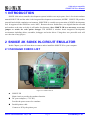
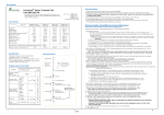
8-Bit Micro-controller
SN8ICE 2K User Manual
SONiX 8-Bit MCU
SN8ICE 2K
USER MANUAL
General Release Specification
SONiX 8-Bit Micro-Controller Development Tools
SONIX reserves the right to make change without further notice to any products herein to improve reliability, function or design. SONIX does not
assume any liability arising out of the application or use of any product or circuit described herein; neither does it convey any license under its patent
rights nor the rights of others. SONIX products are not designed, intended, or authorized for us as components in systems intended, for surgical
implant into the body, or other applications intended to support or sustain life, or for any other application in which the failure of the SONIX product
could create a situation where personal injury or death may occur. Should Buyer purchase or use SONIX products for any such unintended or
unauthorized application. Buyer shall indemnify and hold SONIX and its officers, employees, subsidiaries, affiliates and distributors harmless against
all claims, cost, damages, and expenses, and reasonable attorney fees arising out of, directly or indirectly, any claim of personal injury or death
associated with such unintended or unauthorized use even if such claim alleges that SONIX was negligent regarding the design or manufacture of
the part.
SONiX TECHNOLOGY CO., LTD
Preliminary V0.1
8-bit micro-controller
SN8ICE 2K User Manual
USER MANUAL REVISION HISTORY
Version
Date
Description
VER 0.1
Aug. 2004
V0.1 first issue
HARDWARE REVISION HISTORY
Part
Version
Date
Description
Kernel chip S8KE
Jul. 2004
S8KE first issue.
ICE board
1.2
Jul. 2004
First release. PCB V1.2
ICE board
1.3
Aug. 2004
1. PCB V1.3
2. Adjust the positions of some components.
3. Change the CON1 (I/O port interface) to male type socket.
SONiX TECHNOLOGY CO., LTD
Page 2
Preliminary V0.1
8-bit micro-controller
SN8ICE 2K User Manual
SN8ICE 2K User Manual
USER MANUAL REVISION HISTORY ..................................................................................................... 2
HARDWARE REVISION HISTORY ........................................................................................................... 2
1
INTRODUCTION .................................................................................................................................... 5
2
SN8ICE 2K SONIX IN-CIRCUIT EMULATOR ................................................................................. 5
2.1
2.2
3
PACKAGE CHECK LIST ................................................................................................................. 5
CONNECTION PROCEDURE ......................................................................................................... 6
INSTALLING M2IDE ............................................................................................................................. 7
3.1
3.2
3.3
SYSTEM REQUIRMENT ................................................................................................................. 7
FILE DESCRIPTION......................................................................................................................... 7
INSTALLATION PROCEDURE ...................................................................................................... 7
3.3.1
4
Install M2IDE ............................................................................................................................. 7
QUICK START ...................................................................................................................................... 10
4.1
4.2
4.3
START M2IDE ................................................................................................................................ 10
DEBUG A PROJECT....................................................................................................................... 12
CONNECT TO TARGET BY TRANSITION BOARD.................................................................. 16
5
TROUBLE SHOOTING........................................................................................................................ 18
6
APPENDIX A.......................................................................................................................................... 19
6.1
SN8ICE LIMITATION .................................................................................................................... 19
6.2
6.3
COMPONENTS PLACEMENT ...................................................................................................... 20
SOCKET AND JUMPER DESCRIPTION........................................................................................ 21
6.4
6.5
CON1 AND JP6: IO PORT INTERFACE CIRCUIT SCHEMATIC .............................................................. 22
CLOCK INPUT CIRCUIT............................................................................................................... 23
6.5.1
6.5.2
Install Crystal/Resonator oscillator circuit.................................................................................. 23
Install RC oscillator circuit .......................................................................................................... 24
SONiX TECHNOLOGY CO., LTD
Page 3
Preliminary V0.1
8-bit micro-controller
SN8ICE 2K User Manual
FIGURE INDEX
Figure 2-1 SN8ICE 2K set.................................................................................................................. 5
Figure 3-1 Description of the setup file.............................................................................................. 7
Figure 3-2 License page ..................................................................................................................... 8
Figure 3-3 Select directory for M2IDE .............................................................................................. 8
Figure 3-4 Select M2IDE shortcut...................................................................................................... 8
Figure 3-5 Check again the installation setting .................................................................................. 9
Figure 3-6 Finish installation.............................................................................................................. 9
Figure 4-1 Welcome dialog window ................................................................................................ 10
Figure 4-2 SN8Readme page............................................................................................................ 10
Figure 4-3 Start a new project .......................................................................................................... 11
Figure 4-4 Select the main file for project........................................................................................ 11
Figure 4-5 Edit window.................................................................................................................... 12
Figure 4-6 Code option table example ............................................................................................. 12
Figure 4-7 Complier message........................................................................................................... 13
Figure 4-8 Debug window................................................................................................................ 13
Figure 4-9 Step ................................................................................................................................. 14
Figure 4-10 Set breakpoint ............................................................................................................... 14
Figure 4-11 Run to breakpoint.......................................................................................................... 15
Figure 4-12 Free Run........................................................................................................................ 15
Figure 4-13 Program stops and watch variable ................................................................................ 16
Figure 4-14 The 60 pins socket of transition board is female type.................................................. 16
Figure 4-15 The 60 pins socket of transition board is male type ..................................................... 17
Figure 4-16 Connect Easy-Writer to SN8ICE 2K ............................................................................ 17
Figure 6-1 Component placement .................................................................................................... 20
Figure 6-2 SN8ICE 2K socket and jumper position........................................................................ 21
Figure 6-3 CON1: Generic IO Port .................................................................................................. 22
Figure 6-4 JP6: IO Expansion Port................................................................................................... 22
Figure 6-5 Install Crystal/Resonator oscillator................................................................................. 23
Figure 6-6 Install RC oscillator ........................................................................................................ 24
SONiX TECHNOLOGY CO., LTD
Page 4
Preliminary V0.1
8-bit micro-controller
SN8ICE 2K User Manual
1 INTRODUCTION
SONiX 8-bit micro-controller development system includes two major parts. One is In-circuit emulator
named SN8ICE 2K and the other is the integrated development environment, M2IDE. SN8ICE 2K provides
powerful and reliable emulation environment. SN8ICE2K is a totally new generation of SONiX development
tool. It supports all the SN8P2xxx series MCU. Because the new architecture, new digital function can add
and emulate at the time real chip is still under development. Also, SN8ICE 2K is no necessary to set any
jumper or switch for code option changes. The M2IDE is window based integrated development
environment including editor, assembler, debugger and writer driver. Using these two powerful tools will
save the time of any project.
2 SN8ICE 2K SONIX IN-CIRCUIT EMULATOR
In this Chapter, you will learn how to connect and to install the SN8ICE 2K to your computer.
2.1 PACKAGE CHECK LIST
Figure 2-1 SN8ICE 2K set
SN8ICE 2K
Main circuit to provide the emulator function
DC power adaptor (+7.5V DC)
Provide the power source for emulator
Parallel printer cable
Connect to PC by the printer port.
SONiX TECHNOLOGY CO., LTD
Page 5
Preliminary V0.1
8-bit micro-controller
SN8ICE 2K User Manual
2.2 CONNECTION PROCEDURE
Follow the steps in this section to connect your SN8ICE 2K:
Both SN8ICE 2K and PC should not have the power be turned ON at this
time.
Step 1: Attach the DC adaptor to SN8ICE 2K
Step 2: Turn on PC
Step 3: Locate an unused LPT port of PC
Step 4: Attach SN8ICE 2K to the LPT port using a parallel cable
Now, go to the next section to install your M2IDE.
SONiX TECHNOLOGY CO., LTD
Page 6
Preliminary V0.1
8-bit micro-controller
SN8ICE 2K User Manual
3 INSTALLING M2IDE
3.1 SYSTEM REQUIRMENT
Windows NT/95/98/2000/ME/XP
32MB of available hard drive space
32MB RAM or greater
3.2 FILE DESCRIPTION
M2IDE_Vxxx.exe: M2IDE software package, xxx represents the version.
3.3 INSTALLATION PROCEDURE
3.3.1 Install M2IDE
Follow the steps in this section to install your M2IDE:
Download the setup file from SONiX’s website http://www.sonix.com.tw, or contact the local
agent for this file.
Run the setup file and an introduction window shows like
Figure 3-1 Description of the setup file
SONiX TECHNOLOGY CO., LTD
Page 7
Preliminary V0.1
8-bit micro-controller
SN8ICE 2K User Manual
Click “Next>” to the next step, the License Page. Choose “I agree to the terms of this license
agreement” and click “Next> “ button to next page.
Figure 3-2 License page
This page Select the installation folder. You can change the installation folder just click the
“Change…” button. Then click “Next>” button to next step.
Figure 3-3 Select directory for M2IDE
This step adds the M2IDE shortcut assigning to the application program in the drop-down dialog
box.
Figure 3-4 Select M2IDE shortcut
SONiX TECHNOLOGY CO., LTD
Page 8
Preliminary V0.1
8-bit micro-controller
SN8ICE 2K User Manual
After all information is selected, here show the setting. Just re-check it to see anything wrong.
Figure 3-5 Check again the installation setting
Finally, this window indicates the M2IDE is successfully installed into your system.
Figure 3-6 Finish installation
SONiX TECHNOLOGY CO., LTD
Page 9
Preliminary V0.1
8-bit micro-controller
SN8ICE 2K User Manual
4 QUICK START
In this Chapter, you will learn how to emulate the program using SN8ICE 2K.
4.1 START M2IDE
The first time start M2IDE, a welcome dialog window shows and the SN8Readme file opened. Checked
the checkbox in the welcome window will close the SN8Readme file when launch the M2IDE in next
time. SN8Readme file describe the difference from the previous version of IDE.
Figure 4-1 Welcome dialog window
Figure 4-2 SN8Readme page
SONiX TECHNOLOGY CO., LTD
Page 10
Preliminary V0.1
8-bit micro-controller
SN8ICE 2K User Manual
Then start a new project form the menu, “File-> New Project”
Figure 4-3 Start a new project
Browse the file tree to the M2IDE directory. Choose the “Samples” directory and select
“2501A_TEMPLATE.asm” for the main program of this project
Figure 4-4 Select the main file for project
SONiX TECHNOLOGY CO., LTD
Page 11
Preliminary V0.1
8-bit micro-controller
SN8ICE 2K User Manual
The main file displays at the edit window. Project file tree listed at the left of the edit window.
Figure 4-5 Edit window
4.2 DEBUG A PROJECT
Finish editing the code, start the assembler by pressing the “F7” function key, or select from the
“Debug-> build” menu. A code option window shows to select the correct code option configuration.
Code option is a hard-coding option to choose which part of circuit is used. The detail code option
description is written in each MCU’s datasheet.
Figure 4-6 Code option table example
SONiX TECHNOLOGY CO., LTD
Page 12
Preliminary V0.1
8-bit micro-controller
SN8ICE 2K User Manual
The complier message shows at the Build window, including the warning messages, error messages,
resource status. Program status, like the ROM, RAM usage, is also reported at this stage.
Figure 4-7 Complier message
The program halts at the reset vector if it’s first time to run. A yellow arrow indicates where the
program counter (PC) is. An “ICE” keyword in the status bar indicates that IDE is in the debug mode.
Figure 4-8 Debug window
SONiX TECHNOLOGY CO., LTD
Page 13
Preliminary V0.1
8-bit micro-controller
SN8ICE 2K User Manual
Click “Debug -> Step Over” (F10) from the menu, you could trace Macro or Subroutine of the program
in one step. When finished “Step Over” function, the yellow arrow goes to the next program flow and
stops. In this case, the program jumps to the “Reset” label. The PCL’s value is in red because the
“JMP” instruction changes the PCL value.
Figure 4-9 Step
To set a breakpoint, simply move the cursor to the line where you wish the program to be stopped. Then,
click “Debug-> Break” (F9) from the menu. The red dot represents successful breakpoint setting.
Figure 4-10 Set breakpoint
SONiX TECHNOLOGY CO., LTD
Page 14
Preliminary V0.1
8-bit micro-controller
SN8ICE 2K User Manual
To continue running the program, click “Debug-> Go” (F5). Program runs and the yellow arrow stops
at the breakpoint.
Figure 4-11 Run to breakpoint
Remove all break points by click “Remove all breakpoints” icon (Ctrl+Shift+F9) then “ Click “Debug->
Go” from the menu or press “F5” to continue program execution. The RUN dialogue indicates the
program status and a “Run…” shows in the status bar.
Figure 4-12 Free Run
Press “F5” to stop the program execution.
SONiX TECHNOLOGY CO., LTD
Page 15
Preliminary V0.1
8-bit micro-controller
SN8ICE 2K User Manual
Any time the program stops, “Watch” function could be set to monitor the variable. Select one of the
empty edit box of each page of “Watch” page, and enter the variable name you want to monitor.
Figure 4-13 Program stops and watch variable
Click “Debug-> Reset” from the menu or press “Ctrl+F5” to reset the program. Then, you may emulate
again starting from the program reset vector.
4.3 CONNECT TO TARGET BY TRANSITION BOARD
The CON1 is the generic I/O port including all I/O of SN8P2xxx series. Connect different transition
board to CON1 to meet each MCU’s pin assignment. After ICE board V1.3, the CON1 is male socket.
Please populate 60 pins female socket on transition board and connect transition board to SN8ICE 2K as
following figure:
Figure 4-14 The 60 pins socket of transition board is female type
SONiX TECHNOLOGY CO., LTD
Page 16
Preliminary V0.1
8-bit micro-controller
SN8ICE 2K User Manual
If users populate the 60 pins male socket on transition board. Please connect to SN8ICE 2K through two
60 pins cables as following figure:
Figure 4-15 The 60 pins socket of transition board is male type
The following figure show how to connect Easy-Writer with SN8ICE 2K:
Figure 4-16 Connect Easy-Writer to SN8ICE 2K
Make sure connect Easy-Writer to SN8ICE 2K through the 60 pins cable.
SONiX TECHNOLOGY CO., LTD
Page 17
Preliminary V0.1
8-bit micro-controller
SN8ICE 2K User Manual
5 TROUBLE SHOOTING
Q
The ICE is reset spontaneously sometimes in ICE mode.
A It occurs when the user maps his network printer to the LPT1 that is connected to the ICE system.
To solve it, just map the network printer to LPT2.
Q
ICE can’t work under Windows 2000.
A When ICE works under Windows 2000/ Windows XP, LPT port should be set in the BIOS. Please
check the BIOS about the LPT configuration. It must be EPP, ECP, or Bi-direction.
Q
Could ICE work emulate the 3.3 voltage supply?
A Yes. Just remove the “INTERNAL 5V” jumper (near the RESET button) and supply the 3.3V DC
power to the VDD and VSS pin of CON1 (I/O port interface) by target board.
SONiX TECHNOLOGY CO., LTD
Page 18
Preliminary V0.1
8-bit micro-controller
SN8ICE 2K User Manual
6 APPENDIX A
6.1 SN8ICE LIMITATION
Does not support SN8P1X series chip emulation.
Maximum guarantee MIPS:
8 MIPS at 5V (e.g. 16 MHz crystal and Fcpu = High_Clk / 2)
6 MIPS at 3V
P5.2 open drain function shift to P5.0
Solution: Add open-drain transistor in P5.2 and add pull-up resistor in P5.0
Can’t emulate the ADCKS2 bit for SN8P270XA series chip.
Solution: Always set ADCKS = “0” in SN8ICE 2K emulation.
12-bit ADC missing code is about 8LSB (9-bit resolution in half AVREFH input voltage, 12-bit
resolution in other input voltage)
SONiX TECHNOLOGY CO., LTD
Page 19
Preliminary V0.1
8-bit micro-controller
SN8ICE 2K User Manual
6.2 COMPONENTS PLACEMENT
Follow is the SN8ICE 2K PCB board, named SN8ICE2K version 1.3 and its components placement.
Figure 6-1 Component placement
SONiX TECHNOLOGY CO., LTD
Page 20
Preliminary V0.1
8-bit micro-controller
SN8ICE 2K User Manual
6.3 SOCKET and JUMPER DESCRIPTION
Print Port I/F
FPGA Test Port
Power
Circuit
DC-7.5Vinput
Power switch
Power jumper
Kernel
Chip
IO Protection Circuit
Reset button
Generic IO port
IO Expansion port
Figure 6-2 SN8ICE 2K socket and jumper position
J1: 7.5V DC power supply input.
J2: Printer port socket. Connect to PC.
S1: Power switch
S2: Reset button. Press S2 resets the SN8ICE 2K. The program restarts from address 0.
D5: FPGA(U7) successful configuration indicator
D6: FPGA(12) successful configuration indicator
CON1: Generic IO port, including all SN8P2xxx series I/O
JP1: FPGA Test Pin, reserved for internal usage.
JP6: IO expansion port, reserved for future usage
Power Jumper:
INTERNAL 5V: Short this jumper to provide 5V by SN8ICE 2K power circuit
AVREFH/VDD: AVREFH is the ADC high reference voltage. Short this jumper will connect
the AVREFH to VDD. Remove this jumper and connect external reference
SONiX TECHNOLOGY CO., LTD
Page 21
Preliminary V0.1
8-bit micro-controller
SN8ICE 2K User Manual
voltage to AVREFH pin of CON1 to provide user define ADC high
reference voltage.
AVREFL/VSS: AVREFL s the ADC low reference voltage. Short this jumper will connect
the AVREFL to VSS. Remove this jumper and connect external reference
voltage to AVREFL pin of CON1 to provide user define ADC low reference
voltage..
EXT_TRIG1/2: reserved for future usage
VDD/VSS: reserved for future usage
When the SN8ICE 2K connect to Easy Writer, these two jumpers,
AVREFH/VDD and AVREFL/VSS should be shorted
6.4 CON1 and JP6: IO Port interface Circuit Schematic
Figure 6-4 JP6: IO Expansion Port
Figure 6-3 CON1: Generic IO Port
Figure 6-5 listed the Generic IO port (CON1) pin assignment. All the IO action could be measured from
this port. The JP6 is IO expansion port reserved for future usage.
SONiX TECHNOLOGY CO., LTD
Page 22
Preliminary V0.1
8-bit micro-controller
SN8ICE 2K User Manual
6.5 CLOCK INPUT CIRCUIT
SN8ICE 2K provides two kind of circuit for the clock input. One is RC oscillator and the other is
Crystal oscillator. Following is the picture of how the circuit connected.
6.5.1 Install Crystal/Resonator oscillator circuit
C92: Connect to XOUT
C93: Connect to XIN
Y2: High clock crystal
Figure 6-5 Install Crystal/Resonator oscillator
Select High_Clk code option = 4M_X’tal, 12M_X’tal or 32K_X’tal in assembler
The factory default installation is 4MHz crystal
SONiX TECHNOLOGY CO., LTD
Page 23
Preliminary V0.1
8-bit micro-controller
SN8ICE 2K User Manual
6.5.2 Install RC oscillator circuit
R for RC oscillator
C for RC oscillator
Figure 6-6 Install RC oscillator
Remove the crystal/resonator in Y2
Select High_Clk code option = RC in assembler
SN8ICE 2K RC oscillator frequency table. The following table is for design guidance only.
VDD = 5V
R = 3.3K
R = 5.1K
R = 10K
R = 100K
C = 20 pF
3.333 MHz
2.275 MHz
1.190 MHz
125 KHz
C = 100 pF
1.439 MHz
954 KHz
491 KHz
50 KHz
C = 300 pF
735 KHz
487 KHz
247 KHz
25 KHz
VDD = 3V
R = 3.3K
R = 5.1K
R = 10K
R = 100K
C = 20 pF
2.939 MHz
2.041 MHz
1.103 MHz
124 KHz
C = 100 pF
1.322 MHz
899 KHz
472 KHz
49 KHz
C = 300 pF
698 KHz
470 KHz
245 KHz
24 KHz
SONiX TECHNOLOGY CO., LTD
Page 24
Preliminary V0.1
8-bit micro-controller
SN8ICE 2K User Manual
SONIX reserves the right to make change without further notice to any products herein to improve reliability, function or
design. SONIX does not assume any liability arising out of the application or use of any product or circuit described herein;
neither does it convey any license under its patent rights nor the rights of others. SONIX products are not designed,
intended, or authorized for us as components in systems intended, for surgical implant into the body, or other applications
intended to support or sustain life, or for any other application in which the failure of the SONIX product could create a
situation where personal injury or death may occur. Should Buyer purchase or use SONIX products for any such
unintended or unauthorized application. Buyer shall indemnify and hold SONIX and its officers , employees, subsidiaries,
affiliates and distributors harmless against all claims, cost, damages, and expenses, and reasonable attorney fees arising
out of, directly or indirectly, any claim of personal injury or death associated with such unintended or unauthorized use
even if such claim alleges that SONIX was negligent regarding the design or manufacture of the part.
Main Office:
Address: 9F, NO. 8, Hsien Cheng 5th St, Chupei City, Hsinchu, Taiwan R.O.C.
Tel: 886-3-551 0520
Fax: 886-3-551 0523
Taipei Office:
Address: 15F-2, NO. 171, Song Ted Road, Taipei, Taiwan R.O.C.
Tel: 886-2-2759 1980
Fax: 886-2-2759 8180
Hong Kong Office:
Address: Flat 3 9/F Energy Plaza 92 Granville Road, Tsimshatsui East Kowloon.
Tel: 852-2723 8086
Fax: 852-2723 9179
Technical Support by Email:
[email protected]
SONiX TECHNOLOGY CO., LTD
Page 25
Preliminary V0.1