1
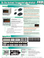
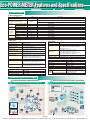
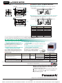
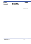
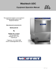
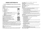
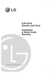
KW4M
Eco-POWER METER
Simple Wattmeter
On the lookout for wasted electricity
in buildings and plants
Dedicated CT
(DIN48x48 size)
For maintenance and control in
Integrated
applications involving energy saving electrical Voltage
energy
and environmental protection
Current
Electricity
charge
Keeping a watchful eye.
Large display for increased visibility
Eco-3 Brothers
Expanded basic functions
Eco-POWER METER
1 model supports 4 compact CTs
Eco-COUNT METER
*When using external
Supports 400 V AC power measurement voltage transformer
Eco-HOUR METER
KW4M Eco-POWER METER
ARCT1B256E-2 '06.11
New
11/2006
http://www.mew.co.jp/ac/e/
AUDIN - 8, avenue de la malle - 51370 Saint Brice Courcelles - Tel : 03.26.04.20.21 - Fax : 03.26.04.28.20 - Web : http: www.audin.fr - Email : [email protected]
Matsushita Electric Works, Ltd.
On the lookout for wasted electricity!
KW4M
FEATURES
Supports 4 types of dedicated CT sensors to
cover wide measuring range
Dedicated CT
Covers a wide measuring range with support for 4 types of CT
(current transformer: sold separately). Also supports 5 A CT of
secondary current input. However, when inputting a secondary
current of 5 A, use a 2-stage configuration by combining with a
dedicated CT.
*4 types of dedicated CT: 5 A/50 A, 100 A, 250 A, and 400 A
5A/50A
250A
Support for 400 V AC power measurement
100A
Capable of 100 V to 400 V AC power measurement.
(If 240 V AC or higher, use with external voltage transformer.)
400A
Basic functions expanded for easier operation
Easy operation with shortcut key
Letters are easy to read with
16-segment LCD
Instantaneous electrical power/
Integrated electrical energy
Since “Instantaneous electrical power” can be
displayed, you can instantly verify the power
being used at the current time.
Current (L1/L2)
Voltage (1-2/2-3)
Electricity charge (yen/dollar/euro/yuan)
Charge display supports four currencies: yen,
dollar, euro, and yuan.
■ Instantaneous electrical power display is possible in addition
to integrated electrical energy.
■ For all power supplies each phase voltage and current display
are possible.
■ Built-in hour meter function.
■ Ability to display an integrated measured power range of up to
9999.99 MWh.
Precise power surveillance is possible by being able to display
down to two decimal places. Also, the display can be
expanded from a 6-digit to a 9-digit display, making it is
possible to display up to 9999999.99 kW.
(9-digit display shown.)
■ Built-in pulse input function (cannot be used when measuring power).
Load time (ON/OFF)
CT is 1/3 the size of our previous models to
save space and install more easily.
Since an hour meter function is built in, you can measure the
power-on time that is over or under the control current.
A compact CT (current transformer) is used that is
approximately 1/3 the size of previous models.
Count value/Preset value
A counter function is built in. By using this “pulse input”,
surveillance other than the electrical power is possible of the
integrated energy in the air or a gas.
Easily connects to PLC
An RS485 communications port comes standard. Up to 99 units
can be connected to a PLC (when using our recommended model).
Using MEWTOCOL as the protocol, it is easy to connect to a
DLU (Web Datalogger Unit).
PRODUCT TYPES
● Main unit
●Dedicated current transformer (CT)
Phase and wire system
Single-phase two-wire system
Single-phase three-wire system
Three-phase three-wire system
Rated input
100 to 120/
200 to 240V AC
Current transformer
Dedicated CT type
(5 A/50 A/100 A/
250 A/400 A)
Terminal type
Part No.
Screw terminal AKW5111
11-pins
AKW5211
● Choosing a CT
(5A/50A)
AKW4801
A
N/A
Rated primary current
5A/50A
100A
250A
400A
Part No.
AKW4801
AKW4802
AKW4803
AKW4804
(250A)
(100A)
(400A)
AKW4803
AKW4802
AKW4804
N/A
N/A
N/A
Please refer to the types of commercial CTs we recommend Note 2).
Dedicated CT
KW4S
(AKW4111/4211) Commercial CT
KW4M
Dedicated CT
A
A
A
(AKW5111/5211)
Notes 1: A: Available, N/A: Not available
2: The commercial CT should have a secondary current rating of 1A.
A
PART NAME
2
EcoPOWER METER
Panasonic
3
MODE Lock
1 2 OP CT1
3 4
CT2
6
4
5
MODE
7
SET
TIME
COUNT
V
CHARGE
kW/kWh
9
Mode indicator (16-segment LCD)
Illuminates when locked.
Lock indicator
Mode indicator
Illuminates when setting a mode.
Output indicator
Illuminates during pulse output.
CT direction
Illuminates when the CT direction is correct and a
notification display
current flows that exceeds the set current value.
6 Value display
Displays the integrated electrical energy, instantaneous
(7-segment)
electrical power, current, voltage, electricity charge,
A
KW4M
8
2
1
1
2
3
4
5
7 MODE key
8 SET key
9 Select key
hour meter time, count, and all settings.
Used to move between different modes.
Used to make settings.
Changes the item displayed.
Used to move between modes.
11/2006
AUDIN - 8, avenue de la malle - 51370 Saint Brice Courcelles - Tel : 03.26.04.20.21 - Fax : 03.26.04.28.20 - Web : http: www.audin.fr - Email : [email protected]
Eco-POWER METER Features and Specifications
SPECIFICATIONS
● Measurement items
Item
Instantaneous electrical power
Unit
kW
Integrated electrical energy
kWh
MWh
Current
Voltage
Electricity
charge *1
Hour meter
L1 (CT1) phase current
L2 (CT2) phase current
Voltage between 1-2
Voltage between 2-3
Yen
Dollars
Euros
Yuan
ON time
OFF time
Pulse input
Data range
0.00 to 9999.99
0.00 to 9999.99kWh to 10.00MWh to 9999.99MWh
9-digit display: 0.00 to 9999999.99kWh
0.0 to 999.9
A
0.0 to 999.9
A
0.0 to 9999.9
V
0.0 to 9999.9
V
0 to 999999
JPY
0 to 9999.99
$
0 to 9999.99
EUR
0 to 9999.99
CNY
0.0 to 99999.9
h (Hour)
0.0 to 99999.9
h (Hour)
0 to 999999
Count
*1: Electricity charge is designed chiefly for managing energy saving. It is not intended to be used for billing.
● Main unit
Pulse input
100 to 120/200 to 240V AC
50/60 Hz common
8VA
85 to 132/170 to 264V AC
(85% to 110% of rated operating voltage)
10ms
–10°C to +50°C +14°F to +122°F
(Storage temperature: –25°C to +70°C –13°F to 158°F)
30 to 85%RH (at 20°C non-condensing)
Ambient humidity
With Backlight 6-digit, 7-segment LCD for settings
Display method
and 4-digit, 16-segment LCD for modes.
Upper display: green, Lower display: amber
Power failure memory method EEP-ROM (Over 100,000 overwrites)
IP66 (front panel with rubber gasket)
Protective construction
Note: Waterproofing (IP66) will be lost in
continuous (permanently attached) installations.
For 11-pin type: approx. 130 g,
Mass
For Screw terminal type: approx. 140 g
Rated operating voltage
Rated frequency
Rated power consumption
Allowable operating
voltage range
Allowable power off time
Ambient temperature
● Communication
Interface
Protocol
Number of connected units
Transmission distance
Conforming to RS485
MEWTOCOL
Max. 99 units
Max. 1,200m
Input mode
Max. counting speed
Pulse input
Input signal
Output mode
Number of digits
Addition (fixed)
2 kHz/30 Hz (selectable by mode)
Min. input signal width: 0.25 ms (when 2 kHz
selected)/16.7 ms (when 30 Hz selected)
ON : OFF ratio = 1 : 1
Contact/No contact (open collector)
• Impedance when shorted: 1 kΩ
• Residual voltage when shorted: Max. 2 V
• Impedance when open: 100 kΩ
HOLD (over count)
6 digits display (0 to 999999) (selectable by mode)
Pulse output (transistor output)
Number of output points
Insulation method
Output type
Output capacity
Pulse width
ON state voltage drop
OFF state leakage current
Pulse
When measuring power
output
unit *2 When measuring pulse input
1 point
Optical coupler
Open collector
100mA 30V DC
Approx. 100ms
1.5V or less
100 μA or less
0.001/0.01/0.1/1/10/100 kWh/Alarm
(selectable by mode)
HOLD (over count)
*2 Power and pulse input are not possible at the same time.
System configuration examples
1
Electric power watching in manufacturing lines
Example
Electric power watching using PLC with Eco-POWER METER
E-mail function also included
2
Electric power data collection and remote watching of plants and buildings
Example
Electric power watching using Web Datalogger Unit with Eco-POWER METER
Have your mobile phone notified by email if there
is a significant increase in electric power usage.
Gathering of logged data
• Power meter
• Water meter
• Dynamometer • Gas meter
Remotely manage collected data on the Web.
Air
con
ditio
ner,
Ligh
ts, O
Web
Datalogger
Unit
Air
utle
con
ts
ditio
ner,
Ligh
ts, O
Air
PCWAY
(Operation Data
Managing Software)
FPΣ
utle
con
ts
ditio
ner,
Ligh
ts, O
utle
Using RS485 (reduced
wiring with two twisted pair
cables), up to 99 Eco-POWER
METERs can be connected.
ts
Ou
tlets
Supermarket
Internet
Telephone infrastructure
All types of networks
Building
Pie graph
Web
Datalogger
Unit
Line graph
Web
Datalogger
Unit
Plant
Food warehouse
3
11/2006
AUDIN - 8, avenue de la malle - 51370 Saint Brice Courcelles - Tel : 03.26.04.20.21 - Fax : 03.26.04.28.20 - Web : http: www.audin.fr - Email : [email protected]
KW4M Eco-POWER METER
■ Dimensions
(mm inch)
■ Terminal Layouts and Wiring Diagrams
General tolerance: ±1.0 ±.039
11-pin type
5.5
.217
● Single-phase, two-wire connection
87.5
3.445
*One current transformer (CT) is required for measurement with single-phase,
two-wire systems.
14.5
.571
Power supply side
Panasonic EcoPOWER METER
MODE Lock
1 2 OP CT1
3 4
CT2
MODE
SET
TIME
COUNT
V
CHARGE
Output
RS485 Output
When
using VT
(䡺44.5)
(䡺1.752)
CT1
K L
CT1
K L
1
2
+ -
+ -
+ -
56 7
4
3
2
kW/kWh
A
Load side
When
using VT
6 7 8 9 10
11
1 2 3 4 5
8
9
10
1 11
+ -
RS485
KW4M
䡺48
䡺1.890
●Single-phase, three-wire and three-phase, three-wire connections
73
2.874
*Two current transformers (CT) are required for measurement with single-phase,
three-wire and three-phase, three-wire systems.
Screw terminal type (M3.5)
5.5
.217
Power supply side
CT1
K L
CT2
K L
RR1
NS2
TT3
When
using VT
(䡺44.5)
(䡺1.752)
RS485 Output
+ -
+ -
56 7
4
8
3
9
2
10
1 11
No.
1
2
3
4
5
6
7
8
9
10
11
Load side
6 7 8 9 10
11
1 2 3 4 5
+ RS485
●Terminal layouts
81.9
3.224
When
using VT
Output + -
CT1
K L
CT2
K L
11-pin type
1, R, R
2, N, S
3, T, T
RS-485 (+)
RS-485 (–)
Pulse output (+)
Pulse output (–)
CT1 (K)/IN
CT1 (L), CT2 (L)
CT2 (K)
0V
Screw terminal type
RS-485 (–)
CT1 (K)/IN
CT1 (L), CT2 (L)
CT2 (K)
0V
Pulse output (+)
Pulse output (–)
1, R, R
2, N, S
3, T, T
RS-485 (+)
• For correct usage, please read “Installation Instructions” thoroughly before using.
• For details, specifications and handling, please refer to the KW4M Eco-POWER METER user’s manual.
• The user’s manual can be downloaded from http://www.mew.co.jp/ac/e/download/index.html.
KW4S Eco-POWER METER
1. Electricity meter that acts like an
industrial component (DIN size: 48×48)
3. Log and track data of integrated electrical
energy usage
Eco-POWER METER is both compact and
inexpensively priced. It is easy to install on your
existing equipment and machinery.
It is easy to load the power usage pulse output into a PLC
or counter.
2. Digitally display integrated electrical
energy and electricity charges
You can digitally display integrated electrical
energy, voltage, current, and electricity charges.
This is handy for managing energy-saving.
4. Centrally manage integrated electrical
energy, voltage, and current
Adopts the RS485 for communication specification.
This allows you to log data (integrated
electrical energy, voltage, and current)
from up to 99 units on a PC and PLC.
● Product types
Product name
Eco-POWER METER main unit
Dedicated current transformer (CT)
Data collection software for Eco-POWER METER
Dedicated CT
Phase and wire system
Rated input
Eco-POWER METER
Current transformer
Terminal type
Screw terminal
Single-phase two-wire system
Dedicated CT type
100 to 120/
11-pin
Single-phase three-wire system
200 to 240V AC
Screw terminal
Commercial CT type
Three-phase three-wire system
(Rated secondary current: 1 A)
11-pin
Can be used with AKW4111 and AKW4211 (For KW4M Eco-POWER METER, AKW5111 and AKW5211.)
Setting of any parameter, and editing and monitoring of all measurement values.
Downloadable from http://www.mew.co.jp/ac/e/download/index.html
Part No.
AKW4111
AKW4211
AKW4121
AKW4221
AKW4801
KW Monitor
• Please refer to “Eco-3 Brothers (ARCT1B226E-1)” catalog.
These materials are printed on ECF pulp.
These materials are printed with earth-friendly vegetable-based (soybean oil) ink.
Please contact ..........
Matsushita Electric Works, Ltd.
Automation Controls Business Unit
Head Office: 1048, Kadoma, Kadoma-shi, Osaka 571-8686, Japan
Telephone: +81-6-6908-1050
Facsimile: +81-6-6908-5781
http://www.mew.co.jp/ac/e/
All Rights Reserved © 2006 COPYRIGHT Matsushita Electric Works, Ltd.
ARCT1B256E-2 200611-1YT
Specifications are subject to change without notice.
Printed in Japan.
11/2006
AUDIN - 8, avenue de la malle - 51370 Saint Brice Courcelles - Tel : 03.26.04.20.21 - Fax : 03.26.04.28.20 - Web : http: www.audin.fr - Email : [email protected]