1
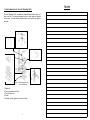
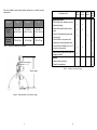
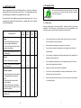
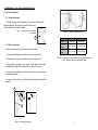
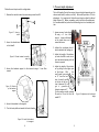
600 User Manual Physipro Standing Chair Physipro inc. 370, 10th Avenue South Sherbrooke (Quebec) J1G 2R7 Phone (819) 823-2252 • Toll Free 1 800 668-2252 • Fax (819) 565-3337 Website: www.physipro.com • Email: [email protected] Physipro Inc. Physipro Inc. is proud to count you among its customers. We would like to thank you for the trust that you have placed in us by choosing one of our products. We have conceived this manual to allow our customers to use the Loki Standing Chair.in an optimal and safe manner. We recommend you consult a qualified professional if adjustments or specific settings are required. You will find herein a table including all the verifications you will have to perform on a regular basis to prolong the operational life of your Loki Standing Chair and ensure its proper functioning. Physipro Inc disclaims responsibility regarding any personal injury or physical damage that may result from the misuse of its product or from any modification brought to its product without its prior consent.. You have purchased a state-of-the-art product that will meet all of your expectations. 2 Notes Table of Contents 1. Main Components of the Loki Standing Chair ...................... 4 2. Specifications ........................................................... 5 3. Recommendations ..................................................... 7 3.1 Safety rules ..................................................... 7 4. Adjustment of the various supports and rests ..................... 8 4.1 Headrest adjustment .......................................... 8 4.1.1 Height adjustment ................................... 8 4.1.2 Depth adjustment .................................... 8 4.2 Adjustment of the height of the laterals, pelvic supports and knee rests ............................. 9 4.3 Adjustment of the width of the laterals, Pelvic supports and knee rests .............................. 9 4.4 Adjustment of the height of the footrest ................ 10 4.5 Adjustment of the angle of the arm rests ................. 10 4.6 Adjustment of the height of the arm rests................ 10 5. Laterals height adjustment .......................................... 11 6. Inclination of the interface .......................................... 12 7. Ventral/Dorsal Configurations ...................................... 13 7.1 Switching from ventral to dorsal ........................... 13 8. Storage ................................................................. 16 9. Maintenance Guide ................................................... 18 10. Warranty .............................................................. 20 3 Notes 1. Main Components of the Loki Standing Chair The Loki Standing Chair is available in three different sizes—small, medium, and tall. Its various components offer a wide variety of options to the users. For more detail, please contact us or consult your purchase order.. 2 3 5 4 Figure 1 – Main components of the standing chair 1. Headrest 2. Pivot and pressure cylinder 3. Tray and arm rest 4. Frame 5. Laterals, pelvic supports, knee rests, boots. 4 10. Warranty The Loki Standing Chair, a product of Les Équipments adaptés Physipro Inc., comes with a 12 month warranty on parts and labour against faulty optional components and new parts replaced by the supplier or a licensed establishment, effective on the delivery date or, if applicable, on the replacement date. This warranty does not cover comfort upholstery, arm rests, and other kinds of upholstery for the warranty period is 30 days. Les équipements Adaptés Physipro inc. Undertakes to repair or replace defective parts for the entirety of the warranty period. To obtain service under this warranty, please contact Les Équipements adaptés Physipro Inc. Or a licensed establishment. Do not return this product without prior consent. In the event that the service falls below the standards set out in this warranty, please send us your comments at the address herein provided, accompanied with the name and address of the supplier, the delivery date, and the serial number of the product. Exclusions and Limitations This warranty shall not apply to products that have been altered or abused accidentally or intentionally, or to products that have be subjected to improper use, negligence, or improper maintenance or storage. This warranty shall not apply to products that have been damaged as a result of a repair or modification performed without the prior consent of Les Équipements adaptés Physipro Inc. Finally, this warranty shall not apply to normal wear and tear of the parts, or should there be a failure to comply with the instructions herein provided. Les Équipements adaptés Physipro inc. is not responsible for any damage that may arise during transportation. 2. Specifications Notes Table 1 – Specifications for the medium model Headrest Height (Midsection— Mid-head) Width Inclination Lateral Depth Width Height Pelvic Support Depth Width Height Knee rest Depth Width Height Rotation Boots Width Velcro Boots Wheels and Frame Wheels Brakes General Characteristics Platform inclination Weight without tray Weight with tray Total width 5½ to 10 in (14 to 25.5 cm) 9½ in (24 cm) Horizontal and vertical 7 in (18 cm) 12 to 15 in (30.5 to 38 cm) 4½ in (11.5 cm) 7 in (18 cm) 10½ to 20 in (27 cm to 51 cm) 5 in (12.5 cm) 5 in (12.5 cm) 3½ to 4 in (8cm to 10 cm) 4 po (10 cm) 0 to 90° 4 in (10 cm) Ø 3 in (7.5 cm) 0 to 90° 50 lb (22.73 kg) 60 lb (27.27 kg) 24 in (61 cm) 43 in to 57½ in (109.2 cm to 146 cm) 39½ in (100 cm) 110 lb (50 kg) Total height (with headrest) Total depth Maximum Capacity Removable Tray 20 5 For more deatils on each model, please contact us or consult your purchase order. Model Small Medium Tall Thoracic Height 25 to 35 in (64 to 89 cm) 35 to 45 in (89 to 114 cm) 45 to 55 in (114 to 140 cm) Maximum Capacity 55 lb (25 kg) 110 lb (50 kg) 155 lb (70 kg) Table 2 – Height and capacity of each model Verification List Supports and rests • Check if the quick release levers are tightened properly. • Ensure that restraint belts work properly . • Check if all upholsteries support the user properly . • Check if there is any wear on the upholstery of all supports and rests. Upon receipt Each week x x x x x 6 months x x • Check if the boot platform is at 1 to 3 inches from the ground. x • Ensure that the tray and arm rests are properly secured. x Cleanup • Clean and wax each part . • Clean the upholsteries. x x x x Table 4 – Standing chair maintenance Thoracic height Figure 2 – Representation of the thoracic height 6 Each month 19 9. MAINTENANCE GUIDE 3. RECOMMENDATIONS Proper maintenance of the Loki Standing Chair is critical to prolong its operational life and ensure the user’s safety. We recommend you have your standing chair inspected by a professional once a year. We verify each of the following points before shipping any unit. We recommend you review these same points on a regular basis as in structed in the following table. Do not use this equipment without having read the user manual in its entirety as it contains important information regarding safety and intended use. 3.1 Safety rules Using the standing chair is very simple and safe. However, some safety rules must be applied. The following list is not exhaustive and it is the responsibility of the user and operators to ensure that this equipment is used properly. Upon receipt Verification List Each week Each month 6 months Frame • Ensure that all fastening components are tightened properly. Check if the rotation system works properly for storage. • Ensure that the platform can be inclined easily. x x x x x x Do not adjust boots to more than 4 inches from the ground as it could affect the stability of the standing chair. Never transport passengers on the supports or lateral arcs. Do not use any materials or equipment on the standing chair other than those provided. Wheels Do not attempt to negotiate an obstacle whose height could jeopardize the stability of the standing chair. • Check if all wheels roll properly . x x • Check if the wheel locking system works properly. x x ding chair and jeopardize its stability. Pressure cylinder • Ensure the pressure of the cylinder is appropriate when incling the user . • Ensure that the control handle works properly . • Check if the tension of the cable linking the control handle to the cylinder is sufficient . • Check if there is any wear on the cylinder rod. Always ask for help when transferring individuals. Do not lift or move the standing chair using its removable parts. Use the secured parts of the frame to do so. x x x x x x x 18 Do not negotiate steep ground as it could damage the wheels of the stan- Never loosen the quick-release levers or collars when there is an individual in the standing chair. x 7 4. Adjustment of the various supports and rests 4.1 Headrest adjustment 4.1.1 Height adjustment To adjust the height of the headrest, all you have to do is loosen the tightening knob (A). By doing this, you will be able to adjust the headrest to the desired height. Figure 3 – Adjustment of the height of the headrest A Figure 25– Open and closed position Position Width 4.1.2 Depth adjustment Depth Follow the next steps to adjust the depth of the headrest : Height Open 24 in (61 cm) Closed 24 in (61 cm) 39½ in (100 cm) 21 in (53.54 cm) 35 to 45 in (89 to 114 cm) 45 in to 55 in (114 to 140 cm) 1. Unscrew screw B using a 4mm Allen wrench for adjustment Y . 2. Unscrew screw C using a 4mm Allen wrench for adjustment Z. Tableau 3 – Comparison of the dimensions in the open and closed positions. *Measures taken from the medium model. 3. Adjust depth according to your needs. Fully tighten both screws. Then adjust the height of the headrest to the comfort of the user. 4. Loosen all screws D using a 4 mm Allen wrench to move the headrest in the desired position. 5. Loosen screw A using a 4 mm Allen wrench to adjust the headrest laterally. A X Y B Z Y D Z C Figure 4 - Headrest adjustment. 8 17 8. Storage The Loki Standing Chair can be easily stored in a car trunk or in a closet. The chair is foldable thanks to the closing system located at the junction of its lateral arcs. The closing of the Loki Standing Chair may result in the misalignment of its wheels, therefore affecting its stability. Verify the wheel alignment every time you store the unit. 4.2 Adjustment of the height of the laterals, pelvic supports and knee rests 6 5 To adjust the height of the supports and rests according to body dimensions, you must loosen, using a 5 mm Allen wrench, screws 1 and 2 for the knee rests, 3 and 4 for the plevic supports, and 5 and 6 for the laterals. 4 3 2 1 Heare the steps to follow: 1. Remove the tray. A 2. Inlcine the interface by about 30°(see page 12 for relevant instructions). Figure 5 –Adjustment of the height of the various supports and rests 3. Lift the front of the standing chair by pulling on tube A. Both arcs will close on each other. 4.3 Adjustment of the width of the laterals, pelvic supports and knee rests. 4. Place the wheels so the standing chair is stable, and then lock them. B Figure 23 - Tube A and base B Width adjustment is performed according to the same procedure as for height adjustment. Using a 5 mm Allen wrench, loosen screw A to laterally adjust the laterals and screw B to laterally adjust the pelvic supports. Loosen scres C and D to adjust the knee rests to the desired positioning. The knee rests are equipped with a rotation system allowing them to be adjusted to the desired angle. To re-open the standing chair, you must ensure that the rear wheels are locked and that the front ones are unlocked. After verification, push on support C on the footrest and the standing chair will be brought back to its open position. A B C Figure 24 - Support C D C 16 Figure 6 – Adjustment of the width of the various supports and rests 9 4.4 Adjustment of the height of the footrest The height of the footrest may be adjusted using the two screws located at the junction of the telescopic tubes. Using a 5 mm Allen wrench, loosen screws A and B so that tubes C and D become movable. To switch from the dorsal to ventral configuration, you must remove the headrest system and switch from the dorsal for the ventral terminal. CAUTION : Adjusting the height of the footrest will automatically modify the settings of all supports and rests. D C A B Figure 7 –Adjustment of the height of the footrest. h Do not adjust the footrest to more than 4 inches from the ground as the Loki Standing Chair could become unstable. 4.5 Adjustment of the angle of the armrests Figure 21 - Dorsal standing chair You can incline the arm rests by initiating the quick-release lever A. Once it is initiated, you can adjust the arm rests to the desired angle (B). B A Figure 8 – Adjustment of the angle of the arm 4.6 Adjustment of the height of the armrests The height of the arm rests may be adjusted by unscrewing the screws of parts 7 and 8 using a 3 mm and a 5 mm Allen wrench. Figure 9 – Adjustment of the height of the armrests 8 7 Figure 22 - Ventral standing chair 10 15 5. Thoracic Height Adjustment Follow the next steps to switch configuration: 1. Remove the ventral terminal by unscrewing screws A and B. B A Figure 17 - Screws A and B The Loki Standing Chair offers various thoracic heights depending on the chosen model (small, medium, and tall). Each model provides a ± 10 inch adjustment. It is important to follow the next steps to adjust the lateral height 9figure 10). Before proceeding, and to facilitate the adjustment, it is recommended that you incline the standing chair in a horizontal position. 1. Loosen screws of parts A and B using a 5 mm Allen wrench. Loosen sufficiently so the inside tubes can be moved with ease. 2. Screw the dorsal terminal in tubes B. 2. Initiate the qui-release lever C which maintains the locking pin. Figure 18 - Dorsal terminal screwed in tubes B 3. Secure the headrest support to the terminal using a 5 mm Allen wrench. Figure 19 - Fixation of the headrest support B 3. Adjust the height of the telescopic rods A and B in order to obtain the desired spacing with the thoracic supports. 4. Adjust the height of the interface by pulling on the higher part of the frame. With the small model, you must C h a ve 13" from the bottom of parts A and B to the top of the footrest (measure D) to get a ground-tofootrest measure of 3". For the medium model, measure D must be 16" and for the tall model 22". 4. Secure the headrest to the support . 5. Turn the boot platform towards the front direction. Figure 20 - Install the headrest in its support 14 A 11 D Figure 10 –Adjustment of the thoracic height You may adjust the footrest to another height according to the needs of the user. It is important, however, not to exceed a ground-to-footrest distance of 4 inches. 5. Using the other hand, activate the control handle of pressure cylinder C. As soon as you will release that handle, the standing chair will stop moving. CAUTION : You may have to adjust some components such as the laterals, pelvic supports, or knee rests. Using a 5 mm Allen wrench, just loosen the screws of parts 1 -2, 3-4, or 5-6. 5. 6. 7. 8. If nobody is in the standing chair while you incline it, it is preferable to pull or push the footboard so it will help you to incline the interface. Tighten the screws of parts A and B. Tighten the quick-release lever C. Tighten, if necessary, the different supports and rests. Place the standing chair in a vertical position using the locking pin control (figure 10). Figure 12 – interface inclination 7. Ventral/Dorsal Configurations You may have to reset the angle of the armrests to the comfort of the user. Just loosen the quick-release lever C, set the armrests in the proper position and tighten the lever. With just a few modifications, the Loki Standing Chair allows switching configuration from ventral to dorsal and vice versa. 7.1 Switching from ventral to dorsal The Loki Standing Chair is equipped with a ventral terminal A (LOKI14110).which is installed on tubes B. Simplified adjustment of the thoracic height for a ±1.5 inch shift A Initiate the quick-release lever D and incline the arm rests to slightly adjust their height (see figure 8). B 6. Inclination of the interface A The Loki Standing Chair allows an inclination of 0°to 90°, that is, from the vertical to the horizontal. Figure 13 - Ventral terminal If the user is in the standing chair, ensure that all belts are secure before changing position. To incline the standing chair in a safe manner, we recommend you follow the next steps : 1. Remove the tray. Figure 14 - Tubes B with support device A To switch from the ventral to dorsal configuration, you must add a dorsal terminal (LOKI14120) and a headrest support D (LOKI14115). C 2. Lock the 4 wheels using the brake pedals (A). 3. Place your foot on the provided base (B). 4. Using one hand, hold the transveral tube D to help you incline the interface. D D A C A B A A Figure 11 - Control handle of pressure cylinder C 12 Figure 15 - Dorsal terminal Figure 16 - Headrest support D 13