1
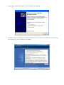
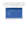
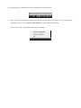
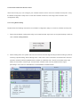
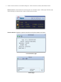
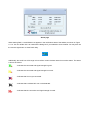
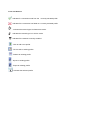
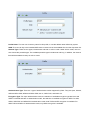
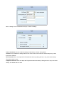
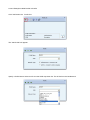
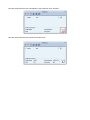
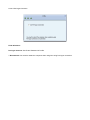
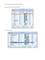
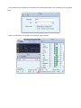
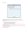
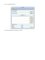
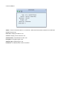
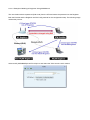
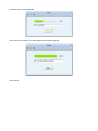
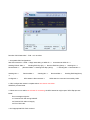
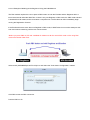
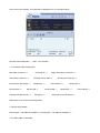
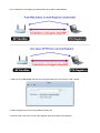
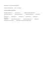
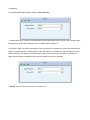
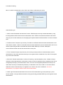
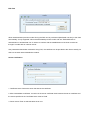
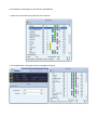
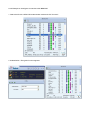
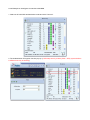
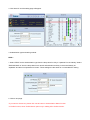
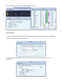
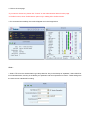
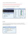
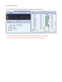
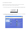
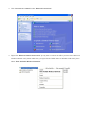
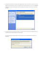
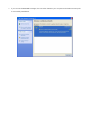
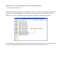
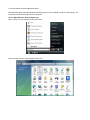
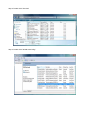
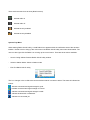
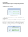
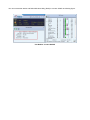
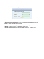
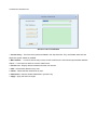
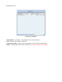
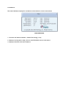
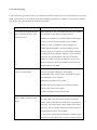
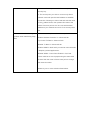
User’s Manual
Wireless 802.11b/g/n
Mini-USB Adapter
COPYRIGHT
Copyright ©2007/2008 by this company. All rights reserved. No part of this publication may be reproduced,
transmitted, transcribed, stored in a retrieval system, or translated into any language or computer language, in
any form or by any means, electronic, mechanical, magnetic, optical, chemical, manual or otherwise, without
the prior written permission of this company
This company makes no representations or warranties, either expressed or implied, with respect to the
contents hereof and specifically disclaims any warranties, merchantability or fitness for any particular purpose.
Any software described in this manual is sold or licensed "as is". Should the programs prove defective
following their purchase, the buyer (and not this company, its distributor, or its dealer) assumes the entire cost
of all necessary servicing, repair, and any incidental or consequential damages resulting from any defect in
the software. Further, this company reserves the right to revise this publication and to make changes from
time to time in the contents thereof without obligation to notify any person of such revision or changes.
Index
Chapter I : Product Information ...........................................................................................................5
1-1 Introduction and safety information ..............................................................................5
1-2 Safety Information .........................................................................................................6
1-3 System Requirements ....................................................................................................7
1-4 Package Contents...........................................................................................................7
1-5 Familiar with your new wireless network card..............................................................8
CHAPTER II : DRIVER INSTALLATION AND CONFIGURATION .............................................9
2-1 Network Card Installation..............................................................................................9
2-2 Connect to Wireless Access Point................................................................................14
2-2-1 Using Ralink Utility .................................................................................................14
2-2-2 Profile .......................................................................................................................18
2-2-2.1 Add/Edit Profile.....................................................................................................20
2-2-2.2 Example to Add Profile in Profile .........................................................................24
2-2-2.3 Pre-logon Connect.................................................................................................26
2-2-3 Network ....................................................................................................................27
2-2-3.1 Example of Adding a Profile to the Network ........................................................29
2-2-4 Advanced ..................................................................................................................31
2-2-4.1 Certificate Management ........................................................................................32
2-2-5 Link Status................................................................................................................33
2-2-5.1 Throughput ............................................................................................................34
2-2-5.2 Statistics.................................................................................................................35
2-2-6 About ........................................................................................................................37
2-2-7 WPS..........................................................................................................................38
2-2-7.1 Example of Adding to Registrar Using PIN Method ............................................40
2-2-7.2 Example of Adding to the Registrar Using the PBC Method................................44
2-2-7.3 Example of Configuring a Network/AP Using PIN or PBC Method....................48
2-3 Security ........................................................................................................................51
2-3-1 Authentication\Encryption Setting - WEP/TKIP/AES.............................................51
2-3-2 802.1x Setting...........................................................................................................53
2-3-3 Example of Configuring a Connection with WEP on ..............................................56
2-3-4 Example to Configure Connection with WPA-PSK.................................................58
2-3-5 Example to Configure Connection with WPA .........................................................60
2-4-1 Using Windows Zero Configuration ........................................................................66
CHAPTER III : AP mode management guide for Windows XP/Vista ..............................................70
3-1.1 Use Ralink soft AP in XP .........................................................................................70
3-1.2 Use Ralink soft AP in Windows Vista ......................................................................71
3-2.1 Start Ralink Soft AP..................................................................................................74
3-2.2 Config AP .................................................................................................................76
3-2.3 Advanced ..................................................................................................................80
3-2.4 Access Control List...................................................................................................81
3-2.5 Associate List............................................................................................................82
3-2.6 About ........................................................................................................................83
CHAPTER IV : APPENDIX..............................................................................................................84
4-1 Hardware Specification ...............................................................................................84
4-2 Troubleshooting ...........................................................................................................85
4-3 Glossary .......................................................................................................................87
4-4 FCC and Other Compliance Statements ......................................................................91
Chapter I : Product Information
1-1 Introduction and safety information
Thank you for purchasing this high-speed 802.11b/g/n wireless network card! Excepting common wireless
standards 802.11b/g, this wireless network card is also 802.11 n compatible - data transfer rate is 300Mbps,
and that’s six times faster than 802.11g wireless network! 802.11 n also provides wider wireless coverage, so
you don’t have to worry if your computer is far from your wireless access point. This wireless network card
also supports MIMO (Multi-In, Multi-Out) technology, which uses two different radio channels to enhance data
transfer rate and wireless coverage.
With easy-to-install USB 2.0 interface - a very common expansion port of computers - plug this wireless
network card into any empty USB port of your computer, just that simple!
Other features of this adapter including:
‧QoS function: Control the bandwidth required for different applications.
‧802.11b/g/n compatible.
‧Supports major encryption methods like WPS, WEP, WPA, and WPA2 encryption.
‧USB 2.0 interface - you can get it installed on your computer in just few seconds!
‧Support Cisco CCX.
1-2 Safety Information
In order to keep the safety of users and your properties, please follow the following safety instructions:
1. This USB wireless network card is designed for indoor use only. DO NOT expose this network card to
direct sun light, rain, or snow.
2. DO NOT put this network card at or near hot or humid places, like kitchen or bathroom. Also, do not left
this wireless network card in the car in summer.
3. This network card is small enough to put in a child’s mouth, and it could cause serious injury or could be
fatal. If they throw the network card, the card will be damaged. PLEASE KEEP THIS NETWORK CARD
OUT THE REACH OF CHILDREN!
4. This network card will become hot when being used for long time (This is normal and is not a malfunction).
DO NOT put the network card on a paper, cloth, or other flammable objects after the network card has
been used for a long time.
5. There’s no user-serviceable part inside the network card. If you found that the network card is not working
properly, please contact your dealer of purchase and ask for help. DO NOT disassemble the network card
by your self, warranty will be void.
6. If the network card falls into water, DO NOT USE IT AGAIN BEFORE YOU SEND THE CARD TO THE
DEALER OF PURCHASE FOR INSPECTION.
7. If you smell something strange or even see some smoke coming out from the network card, switch the
computer off immediately, and call dealer of purchase for help.
1-3 System Requirements
‧An empty USB 2.0 port (May not work on USB 1.1 port, and performance will be greatly reduced)
‧Windows 2000, 2003, XP, or Vista 32/64, WIN7 operating system
‧CD-ROM drive
‧At least 100MB of available disk space
1-4 Package Contents
Before you starting to use this wireless network card, please check if there’s anything missing in the package,
and contact your dealer of purchase to claim for missing items:
□ USB wireless network card (1 pcs)
□ Quick installation guide (1 pcs)
□ User manual CD-ROM (1 pcs)
1-5 Familiar with your new wireless network card
‧USB Connector
‧WPS Button : Press this button 3 seconds to auto link to the AP with WPS encryption.
‧Act LED
LED Name
Light Status
Description
On
Linked to a wireless access point / Transferring data
Off
No wireless activity
Act
CHAPTER II : DRIVER INSTALLATION AND CONFIGURATION
2-1 Network Card Installation
Please follow the following instructions to install your new wireless network card:
1. Insert the USB wireless network card into an empty USB 2.0 port of your computer when computer is
switched on. Never use force to insert the card, if you feel it’s stuck, flip the card over and try again.
2. The following message will appear on your computer, click ‘Cancel’.
3. Insert device driver CD-ROM into the CD/DVD ROM drive of your computer, and install the driver. Choose
the Language you want to install and click ‘Next’.
4. Choose the ‘ Install driver and Boulanger WLAN Utility’ or ‘Install driver only’. When you choose
‘Install driver and Boulanger WLAN Utility’, you can choose the configuration tool used to configure the
wireless network card here. It’s recommended to select ‘Boulanger Configuration Tool’, which provides
fully access to all function of this wireless network card. If you prefer to use the wireless configuration tool
provided by Windows XP, please select ‘Microsoft Zero Configuration Tool’, and then click ‘Next’.
5. Click Install to begin the installation. If you want to review or change any of your installation settings, click
‘Back’. Click ‘Cancel’ to exit the wizard.
6. Please wait while the install procedure is running. When you see this message, please click ‘Finish’ to
complete the driver installation process.
A new icon will appear at lower-right corner of your computer desktop, you can put the mouse cursor on the
icon, and the status of wireless card will be displayed as a popup balloon.
7. When you want to configure your wireless connection, please right click on this icon, and a popup menu
will appear. You can click ‘Launch Config Utilities’ to start configuration program.
If you want to close configuration utility, please click ‘Exit’.
2-2 Connect to Wireless Access Point
There are two ways you can configure your wireless network card to connect to wireless access point: using
the Ralink configuration utility which comes with wireless card driver, and using built-in windows zero
configuration utility.
2-2-1 Using Ralink Utility
Please follow the following instructions to use Ralink configuration utility to connect to wireless access point.
1. Right-click the Ralink configuration utility icon located at lower-right corner of computer desktop, and then
click ‘Launch Config Utilities’.
2. When starting RaUI, the system will connect to the AP with best signal strength without setting a profile or
matching a profile setting. When starting RaUI, it will issue a scan command to a wireless NIC. After two
seconds, the AP list will be updated with the results of a BSS list scan. The AP list includes most used
fields, such as SSID, network type, channel used, wireless mode, security status and the signal
percentage. The arrow icon indicates the connected BSS or IBSS network.
3. There are three sections to the RaUI dialog box. These sections are briefly described as follow.
Button Section: Include buttons for selecting the Link Information page, Profile page, Network page,
Advanced page, the About button, Radio On/Off button and Help.
Function Section: Appears to present information and options related to the button.
Link information page
Profile page
Network page
Advanced page
About page
When starting RaUI, a small Ralink icon appears in the notifications area of the taskbar, as shown in Figure
2-1-15. You can double click it to maximize the dialog box if you selected to close it earlier. You may also use
the mouse's right button to close RaUI utility.
Additionally, the small icon will change color to reflect current wireless network connection status. The status
is shown as follows:
: Indicates the connected and signal strength is good.
: Indicates the connected and signal strength is normal.
: Indicates that it is not yet connected.
: Indicates that a wireless NIC can not be detected.
: Indicates that the connection and signal strength is weak.
2-2-2 Profile
The Profile List keeps a record of your favorite wireless settings at home, office, and other public hot-spots.
You can save multiple profiles, and activate the correct one at your preference. Figure 2-2-1 shows the basic
profile section.
Definition of each field:
Profile Name: Name of profile, preset to PROF* (* indicate 1, 2, 3...).
SSID: The access point or Ad-hoc name.
Network Type: Indicates the networks type, including infrastructure and Ad-Hoc.
Authentication: Indicates the authentication mode used.
Encryption: Indicates the encryption Type used.
Use 802.1x: Shows if the 802.1x feature is used or not.
Cannel: Channel in use for Ad-Hoc mode.
Power Save Mode: Choose from CAM (Constantly Awake Mode) or Power Saving Mode.
Tx Power: Transmitting power, the amount of power used by a radio transceiver to send the signal out.
RTS Threshold: Users can adjust the RTS threshold number by sliding the bar or keying in the value directly.
Fragment Threshold: The user can adjust the Fragment threshold number by sliding the bar or key in the
value directly.
Icons and buttons:
: Indicates if a connection made from the currently activated profile.
: Indicates if the connection has failed on a currently activated profile.
: Indicates the network type is infrastructure mode.
: Indicates the network type is in Ad-hoc mode.
: Indicates if the network is security-enabled.
: Click to add a new profile.
: Click to edit an existing profile.
: Deletes an existing profile.
: Import an existing profile.
: Export an existing profile.
: Activates the selected profile.
2-2-2.1 Add/Edit Profile
There are three methods to open the Profile Editor Dialog box.
1.You can open it by clicking the "Add to Profile" button in the Network page.
2.You can open it by clicking the "Add" button in the Profile page.
3.You can open it by clicking the "Edit" button on the Profile page.
Icons and buttons:
: To the next page.
: Back to the previous page.
: Cancel button.
Profile Name: The user can chose any name for this profile, or use the default name defined by system.
SSID: The user can key in the intended SSID name or select one of the available APs from the drop-down list.
Network Type: There are two types, infrastructure and 802.11 Ad-hoc mode. Under Ad-hoc mode, user can
also choose the preamble type. The available preamble type includes auto and long. In addition, the channel
field will be available for setup in Ad-hoc mode.
Authentication Type: There are 7 type of authentication modes supported by RaUI. They are Open, Shared,
WPA and WPA-PSK, WPA2 and WPA2-PSK, 802.1x, WAPI-PSK, and WAPI-CA.
Encryption Type: For Open authentication mode, the selection of available encryption type are None and
WEP. For Shared and 802.1x authentication mode, the selection of available encryption is WEP. For WPA,
WPA2, WPA-PSK and WPA2-PSK authentication mode, both TKIP and AES encryption is available. For
WAPI-PSK and WAPI-CA authentication mode, only SMS4 encryption is available.
WEP Key: Only valid when using WEP encryption algorithms. The key must be identical to the AP's key.
There are several formats to enter the keys.
1. Hexadecimal - 40bits : 10 Hex characters.
2. Hexadecimal - 128bits : 26 Hex characters.
3. ASCII - 40bits : 5 ASCII characters.
4. ASCII - 128bits : 13 ASCII characters.
Pre-shared Key: This is the key shared between the AP and STA. For WPA-PSK and WPA2-PSK
authentication mode, this field must be filled with a key between 8 and 32 characters in length.
802.1x Setting: This is introduced in the topic of "802.1x Setting"
Power Save Mode: Choose CAM (Constantly Awake Mode) or Power Saving Mode.
Channel: Only available for setting under Ad-hoc mode. Users can choose the channel frequency to start
their Ad-hoc network.
RTS Threshold: User can adjust the RTS threshold number by sliding the bar, or key in the value directly.
The default value is 2347.
Fragment Threshold: User can adjust the Fragment threshold number by sliding the bar or key in the value
directly. The default value is 2346.
2-2-2.2 Example to Add Profile in Profile
Click "Add" below the Profile List.
The "Add Profile" will appear.
Specify a Profile Name. Select an AP from the SSID drop-down list. The AP list from the last Network.
Now the profile which the user set appears in the profile list. Click "Activate".
Now the profile which the user active will connect to AP.
2-2-2.3 Pre-logon Connect
Field definitions:
Pre-logon Connect: Use ID and Password in Profile.
** Recommend: You need to restart the computer when using/non-using Pre-logon connection.
2-2-3 Network
The system will display the information of local APs from the last scan result as part of the Network section.
The Listed information includes the SSID, BSSID, Signal, Channel, Encryption algorithm, Authentication and
Network type
Definition of each field :
SSID: Name of BSS or IBSS network.
Network Type: Network type in use, Infrastructure for BSS, Ad-Hoc for IBSS network.
Channel: Channel in use.
Wireless Mode: AP support wireless mode. It may support 802.11a, 802.11b, 802.11g or 802.11n wireless
mode.
Security-Enable: Indicates if the AP provides a security-enabled wireless network.
Signal: Receive signal strength of the specified network.
Connected network :
When RaUI first runs, it will select the best AP to connect to automatically.
If the user wants to use another AP, they can click "Connect" for the intended AP to make a connection.
If the intended network uses encryption other than "Not Use," RaUI will bring up the security page and let the
user input the appropriate information to make the connection. Please refer to the example on how to fill in the
security information.
When you double click an AP, you can see detailed information about that AP.
The detailed AP information is divided into three parts. They are General, WPS, CCX information and 802.11n
(The 802.11n button only exists for APs supporting N mode.) The introduction is as follows:
General information contains the AP's SSID, MAC address, authentication type, and encryption type.
2-2-3.1 Example of Adding a Profile to the Network
1. Select the AP from the list on the Network tab
2. Click "Add to Profile"
3. The System section will appear at the bottom of the Add Profile window. You can specify your own profile
name.
4. Next, you will see the new profile in the profile list. Click "Activate"
2-2-4 Advanced
1. Wireless mode: Select wireless mode. 2.4GHz, 5GHz and 2.4GHz+5GHz are supported.
2. Wireless Protection: Users can choose from Auto, On, and Off. (This is not supported by 802.11n
adapters.)
2.1. Auto: STA will dynamically change as AP announcement.
2.2. On: The frames are always sent with protection.
2.3. Off: The frames are always sent without protection.
3. TX Rate: Manually select the transfer rate. The default setting is auto. (802.11n wireless cards do not allow
the user to select the TX Rate.)
4. Select Your Country Region Code: There are eight countries to choose from in the country channel list.
(11a ListBox only shows for 5G adapter.)
5. Apply the above changes.
2-2-4.1 Certificate Management
The Certificate Management configuration in this page
2-2-5 Link Status
Status : Current connection status. If no connection, if will show Disconnected. Otherwise, the SSID and
BSSID will show here.
Extra Info : Display link status in use.
Channel : Display current channel in use.
Authentication : Authentication mode in use.
Encryption : Encryption type in use.
Network Type : Network type in use.
IP Address : IP address about current connection.
2-2-5.1 Throughput
Link Speed : Show current transmit rate and receive rate.
Throughout : Display transmits and receive throughput in unit of Mbps.
Link Quality : Display connection quality based on signal strength and TX/RX packet error rate.
Signal Strength 1 : Receive signal strength 1, user can choose to display as percentage or dBm format.
Signal Strength 2 : Receive signal strength 2, user can choose to display as percentage or dBm format.
Signal Strength 3 : Receive signal strength 3, user can choose to display as percentage or dBm format.
2-2-5.2 Statistics
The Statistics page displays detailed counter information based on 802.11 MIB counters. This page translates
that MIB counters into a format easier for the user to understand.
Transmit Statistics:
Frames Transmitted Successfully: Frames successfully sent.
Frames Fail To Receive ACK After All Retries: Frames failed transmit after hitting retry limit.
RTS Frames Successfully Receive CTS: Successfully receive CTS after sending RTS frame.
RTS Frames Fail To Receive CTS: Failed to receive CTS after sending RTS.
Frames Retransmitted Successfully: Successfully retransmitted frames numbers.
Reset counters to zero.
Receive Statistics:
Frames Received Successfully: The number of frames successfully received.
Frames Received With CRC Error: The number of frames received with a CRC error.
Frames Dropped Due To Out-of-Resource: The number of frames dropped due to a resource issue.
Duplicate Frames Received: The number of duplicate frames received.
Reset all the counters to zero.
2-2-6 About
Connect to Ralink's website : Ralink Technology, Corp.
Display Configuration Utility, Driver, and EEPROM version information.
Display Wireless NIC MAC address.
2-2-7 WPS
WPS Configuration: The primary goal of Wi-Fi Protected Setup (Wi-Fi Simple Configuration) is to simplify
the security setup and management of Wi-Fi networks. Ralink STA supports the configuration and setup using
a PIN configuration method or a PBC configuration method through an internal or external Registrar.
WPS AP List: Displays the SSID of the surrounding APs with WPS IE from the last scan result.
PBC: Start to add to AP using PBC configuration method.
PIN: Start to add to Registrar using PIN configuration method. If STA Registrar, remember that enter PIN
Code read from your Enrollee before starting PIN.
Auto: Starts to add to AP by using to select the AP automatically in PIN method.
PIN Code: The user is required to enter an 8-digit PIN Code into Registrar. When an STA is the Enrollee, you
can click "Renew" to re-generate a new PIN Code.
Config Mode: The station serving as an Enrollee or an external Registrar.
After the user clicks PIN or PBC, please do not rescan within two-minutes of the connection. If you want to
abort this setup within the interval, restart PIN/PBC or click "Disconnect" to stop WPS action.
Progress Bar: Displays the rate of progress from Start to Connected.
Status Bar: Displays the current WPS Status.
2-2-7.1 Example of Adding to Registrar Using PIN Method
The user obtains a device password (PIN Code) from the STA and enters the password into the Registrar.
Both the Enrollee and the Registrar use PIN Config method for the configuration setup. The following image
outlines the process.
Select an AP (SSID/BSSID) that STA will join to and Select the "PIN/ numeric code" method.
Select "Enrollee" from the Config Mode drop-down list.
Enter the PIN Code of the STA into the Registrar when prompted by the Registrar.
If you use Microsoft Window Connection Now as an External Registrar, you must start PIN connection at STA
first. After that, search out your WPS Device name and MAC address at Microsoft Registrar. Add a new
device and enter PIN Code of STA at Microsoft Registrar when prompted.
Click "PIN" to enter the PIN
The result should appear as the image below.
Configure one or more credentials
Then connect successfully. The result appear as the following image.
Click "Finish"
Describe "WPS Status Bar" - "PIN - xxx" as follow:
1. Acceptable PIN Configurations:
Start PIN connection - SSID ~> Begin associating to WPS AP ~> Associated to WPS AP ~>
Sending EAPOL-Start ~>
Received M2 ~>
Sending M5 ~>
Sending EAP-Rsp (ID) ~> Receive EAP-Req (Start) ~> Sending M1 ~>
(Received M2D ~> Sending EAP-Rsp (ACK))
Received M6 ~>
Sending M7 ~>
~> Sending M3 ~> Received M4 ~>
Received M8 ~>
Sending EAP-Rsp(Done)
~>
Configured ~>
WPS status is disconnected ~>
WPS status is connected successfully-SSID
2. WPS configuration doesn't complete after a two-minute connection:
WPS EAP process failed.
3. When errors occur within two minutes of connecting, the WPS status bar might report "WPS Eap process
failed".
Error messages might be:
3.1 Receive EAP with wrong NONCE.
3.2 Receive EAP without integrity.
3.3 Error PIN Code.
4. An inappropriate EAP-FAIL received.
2-2-7.2 Example of Adding to the Registrar Using the PBC Method
The PBC method requires the user to press a PBC button on both the Enrollee and the Registrar within a
two-minute interval called the Walk Time. If there is only one Registrar in PBC mode, the PBC mode selected
is obtained from ID 0x0004, and is found after a complete scan. The Enrollee can then immediately begin
running the Registration Protocol.
If the Enrollee discovers more than one Registrar in PBC mode, it MUST abort its connection attempt at this
scan and continue searching until the two-minute timeout.
*Before you press PBC on STA and candidate AP. Make sure all APs aren't PBC mode or APs using PBC
mode have left their Walk Time.
Select an AP (SSID/BSSID) that STA will join to and Select the "Push-button Configuration" method.
Click PBC to start the PBC connection.
Push the PBC on AP.
The progress bar as shown in the figure below indicates that scanning progress.
When one AP is found, join it.
Configure and receive one or more credential(s).
Then connect successfully. The result will be displayed as it is in the figure below.
Describe "WPS Status Bar" - "PBC - xxx" as follow :
1. A successful PBC Configuration :
Start PBC connection ~>
Scanning AP ~>
Begin associating to WPS AP ~>
Associated to WPS AP ~>
Sending EAPOL-Start ~>
Receive EAP-Rsp (Start) ~>
Sending M1 ~>
Received M4 ~>
Sending M5 ~>
Sending EAP-Rsp (Done) ~>
Received M2 ~>
Received M6 ~>
Configured ~>
Sending EAP-Rsp (ID) ~>
Sending M3 ~>
Sending M7 ~>
WPS status is disconnected ~>
WPS status is connected successfully-SSID
2. No PBC AP available :
Scanning AP ~> No PBC AP available ~> Scanning AP ~> No PBC AP available ~>...
3. Too Many PBC AP available :
Received M8 ~>
Scanning AP ~> Too Many PBC AP available ~> Scanning AP ~> Too Many PBC AP available ~>...
4. WPS configuration doesn't complete after two-minute connection:
WPS Eap process failed.
5. When Errors occur within two-minutes of establishing a connection, the WPS status bar might report "WPS
Eap process failed".
Error messages might be:
5.1 Receive EAP with wrong NONCE.
5.2 Receive EAP without integrity.
5.3 An inappropriate EAP-FAIL received.
Describe "Multiple PBC session overlaps" as follow :
1. Dual bands:
AP1 is a G-Band AP using PBC mode. (ID = 0x0004)
AP2 is a A-Band AP using PBC mode. (ID = 0x0004)
They have the same UUID-E.
STA would regard these two APs as a dual-radio AP and select one band to connect.
2. Different UUID-E :
AP1 is a G-Band AP using PBC mode. (ID = 0x0004)
AP2 is a G-Band AP using PBC mode. (ID = 0x0004)
They have the different UUID-E.
STA would regard these two APs as two different APs and wait until only one PBC AP is available.
2-2-7.3 Example of Configuring a Network/AP Using PIN or PBC Method
1. Select an AP (SSID/BSSID) that STA will config and Select the "PIN/ numeric code" method.
2. Select "Registrar" from the Config Mode drop-down list.
3. Enter the PIN Code of the STA into the Registrar when prompted by the Registrar.
4. Enter the details of the credential and change configurations (SSID, Authentication, Encryption and Key)
manually if needed.
5. Start PIN or PBC. The following procedures are as similar as section 2-2-7.1 (PIN Enrollee Setup) or
section 2-2-7.2(PBC Enrollee Setup),
6. If your AP Enrollee has been configured before the WPS process, the credential you set in advance will be
updated to the AP itself. Otherwise, after a successful registration, the AP Enrollee will be re-configured with
the new parameters, and the STA Registrar will connect to the AP Enrollee with these new parameters.
Describe "WPS Status Bar" - "PIN - xxx" as follow :
A successful PIN Configuration :
Start PIN connection - SSID ~>
Sending EAPOL-Start ~>
Receive M3 ~>
Begin associating to WPS AP ~>
Sending EAP-Rsp (ID) ~>
Sending M4 ~>
Receive M5 ~>
Associated to WPS AP ~>
Receive M1 ~>
Sending M6 ~>
Sending M2 ~>
Receive M7 ~>
Sending M8 ~>
Receive EAP Rsp (Done) ~>
disconnected ~>
Sending EAP Rsp (ACK) ~>
Configured ~>
WPS status is
WPS status is connected successfully-SSID
Describe "WPS Status Bar" - "PBC - xxx" as follow :
A successful PBC Configuration :
Start PBC connection ~>
Associated to WPS AP ~>
Scanning AP ~>
Begin associating to WPS AP ~>
Sending EAPOL-Start ~>
Sending EAP-Rsp (ID) ~>
Receive M1
~>
Sending M2 ~>
Receive M3 ~>
Sending M4 ~>
Receive M5 ~>
Sending M6 ~>
Receive M7 ~>
Sending M8 ~>
Receive EAP Rsp (Done) ~>
WPS status is disconnected ~>
Sending EAP Rsp (ACK) ~>
WPS status is connected successfully-SSID
Configured ~>
2-3 Security
2-3-1 Authentication\Encryption Setting - WEP/TKIP/AES
1. Authentication Type: There are 7 authentication modes supported by RaUI. They are open, Shared, WPA
and WPA-PSK, WPA2 and WPA2-PSK, 802.1x, WAPI-PSK and WAPI-CA.
2. Encryption Type: For Open authentication mode, the selection of available encryption type are None and
WEP. For Shared and 802.1x authentication mode, the selection of available encryption is WEP. For WPA,
WPA2, WPA-PSK and WPA2-PSK authentication mode, both TKIP and AES encryption is available. For
WAPI-PSK and WAPI-CA authentication mode, only SMS4 encryption is available.
3. 802.1X: This is introduced in the topic of Section 2-3-2.
4. Pre-shared Key: This is the shared key between the AP and STA. If operating in WPA-PSK and
WPA2-PSK authentication mode, this field must be filled with a key between 8 and 32 characters in length.
5. WEP Key: Only valid when using WEP encryption algorithm. The key must match the AP's key. There are
several formats to enter the keys.
1. Hexadecimal - 40bits: 10 Hex characters.
2. Hexadecimal - 128bits: 32Hex characters.
3. ASCII - 40bits: 5 ASCII characters.
4. ASCII - 128bits: 13 ASCII characters.
2-3-2 802.1x Setting
802.1x is used for authentication of the "WPA" and "WPA2" certificate by the server.
Authentication type:
1. PEAP: Protect Extensible Authentication Protocol. PEAP transport securely authenticates data by using
tunneling between PEAP clients and an authentication server. PEAP can authenticate wireless LAN clients
using only server-side certificates, thus simplifying the implementation and administration of a secure wireless
LAN.
2. TLS/Smart Card: Transport Layer Security. Provides for certificate-based and mutual authentication of the
client and the network. It relies on client-side and server-side certificates to perform authentication and can be
used to dynamically generate user-based and session-based WEP keys to secure subsequent
communications between the WLAN client and the access point.
3. TTLS: Tunneled Transport Layer Security. This security method provides for certificate-based, mutual
authentication of the client and network through an encrypted channel. Unlike EAP-TLS, EAP-TTLS requires
only server-side certificates.
4. EAP-FAST: Flexible Authentication via Secure Tunneling. It was developed by Cisco. Instead of using a
certificate, mutual authentication is achieved by means of a PAC (Protected Access Credential) which can be
managed dynamically by the authentication server. The PAC can be supplied (distributed one time) to the
client either manually or automatically. Manually, it is delivered to the client via disk or a secured network
distribution method. Automatically, it is supplied as an in-band, over the air, distribution. For tunnel
authentication, only support "Generic Token Card" authentication.
5. LEAP: Light Extensible Authentication Protocol is an EAP authentication type used primarily by Cisco
Aironet WLANs. It encrypts data transmissions using dynamically generated WEP keys, and supports mutual
authentication.
6. MD5-Challenge: Message Digest Challenge. Challenge is an EAP authentication type that provides
base-level EAP support. It provides for only one-way authentication - there is no mutual authentication of
wireless client and the network.(Only support XP)
Session Resumption: The user can choose "Disable" and "Enable".
Tunnel Authentication:
1. Protocol: Tunnel protocol, List information include "EAP-MSCHAP v2", "EAP-TLS/Smart card", "Generic
Token Card", "CHAP", "MS-CHAP", "MS-CHAP-V2", "PAP" and "EAP-MD5".
2. Tunnel Identity: Identity for tunnel.
3. Tunnel Password: Password for tunnel.
ID \ PASSWORD
1. Authentication ID/Password: The identity, password and domain name for server. Only "EAP-FAST" and
"LEAP" authentication can key in domain name. Domain names can be keyed in the blank space.
2. Tunnel ID/Password: Identity and Password for the server.
Client Certification
Use Client certificate: Client certificate for server authentication.
EAP Fast
Allow unauthenticated provision mode: During the PAC can be provisioned (distributed one time) to the client
automatically. It only supported "Allow unauthenticated provision mode" and use "EAP-MSCHAP v2"
authentication to authenticate now. It causes to continue with the establishment of the inner tunnel even
though it is made with an unknown server.
Use protected authentication credential: Using PAC, the certificate can be provided to the client manually via
disk or a secured network distribution method.
Server Certification
1. Certificate issuer: Select the server that issues the certificate.
2. Allow intermediate certificates: It must be in the server certificate chain between the server certificate and
the server specified in the "certificate issuer must be" field.
3. Server name: Enter an authentication sever root.
2-3-3 Example of Configuring a Connection with WEP on
1. Select an AP with WEP encryption and click "Connect".
2. The Authentication \ Encryption function will appear as below;
3. Enter 1234567890 in the Key#1 Hexadecimal field. This value is same as our intended AP's setting.
4. Click "OK". The dialog box will appear as below;
2-3-4 Example to Configure Connection with WPA-PSK
1. Select the AP with a WPA-PSK authentication mode and click "Connect".
2. Authentication \ Encryption function appears.
3. Select WPA-PSK as the Authentication Type. Select TKIP or AES encryption. Enter the WPA Pre-Shared
Key as "12345678".
4. Click "OK". Be careful, if the WPA Pre-Shared Key entered is not correct, you won’t be able to exchange
any data frames, even though the AP can be connected.
2-3-5 Example to Configure Connection with WPA
1. Select an AP with WPA authentication mode and click "Connect".
2. The Authentication \Encryption function pop up. (If AP setup security to Both (TKIP + AES), system defines
is AES that security is severely.)
3. Click "8021X" and the setting page will appear.
4. Authentication type and setting method :
PEAP :
1. Select "PEAP" as the Authentication type from the drop-down list. Key-in "wpatest2" for the identity. "Select
"EAP-MSCHAP v2" from the drop-down list for tunnel authentication and key-in the tunnel identity as
"wpatest2" and the tunnel password as "test2". These settings are the same as our intended AP's setting.
2. Click to next page.
*If you want to disconnect, please click cancel button in Authentication Status function.
*In Profile function, show "Profile Name" option only in adding AP to Profile function.
3. If the connection is successful, the dialog will appear as below.
TLS / Smart Card :
1. "Select TLS / Smart Card" from the Authentication type drop-down list. TLS only requires the identification
to be set as "wpatest2" for server authentication.
2. TLS must use client certification. Click "Client Certification" and select a certification for server
authentication.
3. Click to the next page.
*If you want to disconnect, please click "Cancel" on the Authentication Status function page.
*In Profile function, show "Profile Name" option only in adding AP to Profile function.
4. If it connected successfully, the result will appear as in the image below.
TTLS :
1. Select TTLS from the Authentication type drop-down list. Key-in the identity as "wpatest2". Select CHAP for
tunnel authentication, and key-in the identity as "wpatest2" and tunnel password as "test2". These settings are
the same as our intended AP's setting.
2. Click "OK". The dialog box should appear as the image below.
*If you want to disconnect, please click "Cancel" on the Authentication Status function page.
*In Profile function, show "Profile Name" option only in adding AP to Profile function.
3. If the connection is successful, the dialog box will appear as the image below.
EAP-FAST :
1. Select EAP-FAST from the Authentication type drop-down list. Key-in the identity as "wpatest2" and a
domain name into the blank field. The tunnel identity is "wpatest2" and password is "test2". These setting are
the same as our intended AP's setting.
2. Click to the next page.
3. If the connection is successful, the dialog box will appear as the image below.
*If you want to disconnect, please click "Cancel" on the Authentication Status function page.
*In Profile function, show "Profile Name" option only in adding AP to Profile function.
2-4-1 Using Windows Zero Configuration
Windows XP has a built-in wireless network configuration utility, called as ‘Windows Zero Configuration’
(WZC). You can also use WZC to configure your wireless network parameter:
1. Right-click Ralink configuration utility icon and select ‘Use Zero Configuration as Configuration utility’.
2. Click ‘Start’ button (should be located at the bottom-left corner of windows desktop), click ‘Control Panel’,
then click ‘Network and Internet Connections’ in Control Panel.
3. Click ‘Connect to a network’ under ‘Network Connections’.
4. Right-click ‘Wireless Network Connection’ (it may have a number as suffix if you have more than one
wireless network card, please make sure you right-click the ‘Ralink 802.11n Wireless LAN Card’), then
select ‘View Available Wireless Networks’.
5. All wireless access points in proximity will be displayed here. If the access point you want to use is not
displayed here, please try to move your computer closer to the access point, or you can click ‘Refresh
network list’ to rescan access points. Click the access point you want to use if it’s shown, then click
‘Connect’.
6. If the access point is protected by encryption, you have to input its security key or passphrase here. It
must match the encryption setting on the access point.
If the access point you selected does not use encryption, you’ll not be prompted for security key or
passphrase.
7. If you can see ‘Connected’ message, the connection between your computer and wireless access point
is successfully established.
CHAPTER III : AP mode management guide for Windows XP/Vista
3-1.1 Use Ralink soft AP in XP
Windows XP provides WPA support to hotfix Q815485, however, you have to make sure that hotfix Q815485
(requires XP SP1 to be installed) has been installed in your system before you can start using the WPA
features. You can check the installation of hotfix in add/remove software page under control panel.
Currently, Ralink’s utility (RaConfig) provides WPA-PSK supplicant functionality if the user requires the WPA
function. RaConfig will prompt the user to make a selection when it first runs after XP boots.
3-1.2 Use Ralink soft AP in Windows Vista
Ralink Soft AP utility needs the Windows AutoConfig service to be enabled in order to work properly. The
procedure to start AutoConfig service is as follows.
How to Start Windows AutoConfig Service
Step 1: Select "Control Panel" from the start menu
Step 2: Double-click the "Administrative Tools" icon
Step 3: Double-click "Services"
Step 4: Double-click "WLAN AutoConfig"
Step 5: Manage the settings through the AutoConfig Properties dialog box
3-2.1 Start Ralink Soft AP
Clicking
will bring up the selection window and let the user make a selection. It can switch between
"AP mode" and "Station mode"
If "Switch to Station mode" is selected, please refer to the station’s help file.
If "Switch to AP mode" is selected, the system will display Main Window.
Main window
There are six function items to use (Red line area).
-
Config AP: This item is used to configure basic settings
-
Advanced : This item is used to configure advanced settings
-
Access Control List: This item is used to edit the access control lis.
-
Associate list : This item displays the stations which are currently connected to Soft AP.
-
About : This item displays the Ralink driver and utility information
There are five information text to show (Green line area)
- SSID: SoftAP's SSID.
- Mode : RF band, 2.4G or 5G.
- Channel : Channel number.
- IP: IP address.
- Mask: Subnet mask.
There are three state icons to show (Blue line area).
: Indicate radio on
: Indicate radio off
: Indicate security enabled
: Indicate security disabled
System Tray Menu
When starting Ralink Soft AP utility, a small Ralink icon appears within the notification area of the windows
taskbar . Double click it to bring up the main menu if the Ralink Soft AP utility menu was closed earlier. The
user can also right-click the Ralink icon to bring up the control menu. There are three actions available.
- Launch Config Utilities: Restore Ralink Soft AP utility window
- Switch to Station Mode: Switch to Station mode
- Exit: End Ralink Soft AP utility
The icon changes color to reflect the current wireless network connection status. The status is indicated as
follows:
:Indicate connected and signal strength is good.
:Indicate connected and signal strength is normal.
:Indicate connected and signal strength is weak.
:Indicate wireless NIC not detected.
:Indicate not connected yet.
3-2.2 Config AP
User can configure Soft AP basic settings in Config AP Window. You can press next button
to configure
step by step.
First page in Config AP Window
First page settings:
1. SSID: SoftAP's name. System default is SoftAP-XX ( XX is last two numbers of MAC address).
2. Hide SSID: Don’t display the AP name. The system default is to not hide the SSID.
3. Wireless Mode: Select wireless mode. 2.4G and 5G are supported. System default is 2.4G. ( 802.11 B/G/N
mix selection item only exists for B/G/N adapter )
Second page in Config AP Window
Second page settings:
1. Select Country Region: The Country Region Code allows the user to specify the available channel list
based on their country's regulations.Country channel list: Country channel list. (11A ListBox only shows for
A/B/G adapter.)
2. Channel: Select the AP’s operating channel manually. System default is channel 1.
3. Allow BW40 MHz: Allow BW40 MHz capability.
Third page in Config AP Window
Third page settings:
1. Authentication: The available authentication mode are Open, Shared, WPA-PSK, WPA2-PSK, and
WPA-PSK / WPA2-PSK.
2. Encryption: For Open and Shared systems, the available options are None and WEP. For WPA-PSK and
WPA-PSK / WPA2-PSK, the available options are TKIP and AES. For WPA2-PSK, the available options are
TKIP, AES, and BOTH.
If Authentication type is Open or Shared and Encryption type is WEP, and press next button, you will see the
figure as Figure 2-2-4. If Authentication type is WPA-PSK, WPA2-PSK, or WPA-PSK / WPA2-PSK and
Encryption type is TKIP, AES, or BOTH, and press next button, you will see the figure as Figure 2-2-5. If
Authentication type is Open and Encryption type is Not Use, and press next button, you will finish settings and
close Config AP window.
Fourth page in Config AP Window
Fourth page settings:
1. Default Tx Key: Select Tx key index from 1 to 4.
2. Key Format:
Input 10 or 26 characters for WEP Key if select Hex, but input 5 or 13 characters for WEP
Key if select ASCII.
3. WEP Key: Input shared secret key between station and AP.
Fourth page in Config AP Window
Fourth page settings:
1. WPA-PSK Key: Input shared secret key between station and AP. Key length is 8~63 ASCII characters or 64
HEX characters.
2. Group Rekey Interval: AP will update group key per specified interval time.
After finish four(or three) page settings, you will exit Config AP window, and return to Main window. Change of
settings will be shown in Main window as Figure 2-2-6.
Return to Main Window after exit Config AP Window
You can use another station and Ralink Wireless Utility (RaUI) to connect SoftAP as following figure.
Use RaUI to connect SoftAP
3-2.3 Advanced
User can configure Soft AP advanced settings in Advanced Window.
Advanced Window
1. No forwarding among wireless clients: If apply this item, packets between wireless clients are not
forwarding by Soft AP. The system default is forwarding.
2. Beacon interval (ms): The time span between two successive beacons. System default is 100 ms.
3. TX Power: The transmitting power of Soft AP. System default is 100%.
4. Idle Time: The allowed idle time before proceeding with the authentication. The default is 300.
5. Apply: Apply the above changes.
3-2.4 Access Control List
Access Control List Window
1. Access Policy:There are three policies available in the drop-down list. They are Disable, Allow All, and
Reject All. System default is disabled.
2. Mac Address: In order to add an entry into the access control list, the user should input the MAC address
without "-" in the text box and then click the "Add" button.
3. Access List:Display all Mac Addresses that the user has set.
4. Add:Add the Mac address set by user.
5. Delete:Delete the Mac address set by user.
6. Remove All:Remove all Mac addresses in [Access List].
7. Apply:Apply the above changes.
3-2.5 Associate List
Associate List Window
1. MAC Address:The station's Mac address of the current connection.
2. AID:The association identifier of the clien.
3. Power Saving Mode:Support Power Saving Mode on the currently connected station.
4. Status:The link status of the current connection. (Only 802.11n wireless cards support)
3-2.6 About
The About Window displays the wireless card and driver version information.
About Window
1. Connects to Ralink’s website : Ralink Technology, Corp.
2. Displays Configuration Utility, Driver and EEPROM version information.
3. Displays Wireless NIC MAC address.
CHAPTER IV : APPENDIX
4-1 Hardware Specification
Standards:
IEEE 802.11b/g/n
Interface:
USB 2.0 (USB 1.1 Compatible)
Frequency Band:
2.4000 ~ 2.4835GHz (Industrial Scientific Medical Band)
Data Rate:
11b: 1/2/5.5/11Mbps
11g: 6/9/12/24/36/48/54Mbps
11n (20MHz): MCS0-15, 32 with Half Guard Interval Support (up to 144Mbps)
11n (40MHz): MCS0-15, 32 with Half Guard Interval Support (up to 300Mbps)
Securities:
WEP 64/128, WPA, WPA2
Cisco CCX V1.0, V2.0 & V3.0 Compliance
Antenna:
Internal 2 Antennas with Two TX and Two RX
Drivers:
Windows 2000/XP/2003/Vista/WIN 7
LEDs:
Link/Activity
Transmit Power:
13dBm ± 2dBm
Temperature:
32~131°F (0 ~ 55°C)
Humidity:
10-95% (NonCondensing)
Certification:
FCC, CE
4-2 Troubleshooting
If you encounter any problem when you’re using this wireless network card, don’t panic! Before you call your
dealer of purchase for help, please check this troubleshooting table, the solution of your problem could be
very simple, and you can solve the problem by yourself!
Scenario
Solution
I can’t find any wireless access
Click ‘Rescan’ for few more times and see if you can find
point / wireless device in ‘Site
any wireless access point or wireless device.
Survey’ function.
Please move closer to any known wireless access point.
‘Ad hoc’ function must be enabled for the wireless
device you wish to establish a direct wireless link.
Please adjust the position of network card (you may
have to move your computer if you’re using a notebook
computer) and click ‘Rescan’ button for few more times.
If you can find the wireless access point or wireless
device you want to connect by doing this, try to move
closer to the place where the wireless access point or
wireless device is located.
Nothing happens when I click
Please make sure the wireless network card is inserted
‘Launch config utilities’
into your computer’s USB port. If the Ralink
configuration utility’s icon is black, the network card is
not detected by your computer.
Reboot the computer and try again.
Remove the card and insert it into another USB port.
Remove the driver and re-install.
Contact the dealer of purchase for help.
I can not establish connection
with a certain wireless access
point
1. Click ‘Connect’ for few more times.
2. If the SSID of access point you wish to connect is
hidden (nothing displayed in ‘SSID’ field in ‘Site Survey’
function), you have to input correct SSID of the access
point you wish to connect. Please contact the owner of
access point to ask for correct SSID.
3. You have to input correct passphrase / security key to
connect an access point with encryption. Please contact
the owner of access point to ask for correct passphrase /
security key.
4. The access point you wish to connect only allows
network cards with specific MAC address to establish
connection. Please go to ‘About’ tab and write the value
of ‘Phy_Addess’ down, then present this value to the
owner of access point so he / she can add the MAC
address of your network card to his / her access point’s
list.
The network is slow / having
problem when transferring large
Move closer to the place where access point is located.
Enable ‘Wireless Protection’ in ‘Advanced’ tab.
files
Try a lower TX Rate in ‘Advanced’ tab.
Disable ‘Tx Burst’ in ‘Advanced’ tab.
Enable ‘WMM’ in ‘QoS’ tab if you need to use multimedia
/ telephony related applications.
Disable ‘WMM – Power Save Enable’ in ‘QoS’ tab.
There could be too much people using the same radio
channel. Ask the owner of the access point to change
the channel number.
Please try one or more solutions listed above.
4-3 Glossary
1. What is the IEEE 802.11g standard?
802.11g is the new IEEE standard for high-speed wireless LAN communications that provides for up to 54
Mbps data rate in the 2.4 GHz band. 802.11g is quickly becoming the next mainstream wireless LAN
technology for the home, office and public networks.
802.11g defines the use of the same OFDM modulation technique specified in IEEE 802.11a for the 5
GHz frequency band and applies it in the same 2.4 GHz frequency band as IEEE 802.11b. The 802.11g
standard requires backward compatibility with 802.11b.
The standard specifically calls for:
‧A new physical layer for the 802.11 Medium Access Control (MAC) in the 2.4 GHz frequency band,
known as the extended rate PHY (ERP). The ERP adds OFDM as a mandatory new coding scheme
for 6, 12 and 24 Mbps (mandatory speeds), and 18, 36, 48 and 54 Mbps (optional speeds). The ERP
includes the modulation schemes found in 802.11b including CCK for 11 and 5.5 Mbps and Barker
code modulation for 2 and 1 Mbps.
‧A protection mechanism called RTS/CTS that governs how 802.11g devices and 802.11b devices
interoperate.
2. What is the IEEE 802.11b standard?
The IEEE 802.11b Wireless LAN standard subcommittee, which formulates the standard for the industry.
The objective is to enable wireless LAN hardware from different manufactures to communicate.
3. What does IEEE 802.11 feature support?
The product supports the following IEEE 802.11 functions:
‧CSMA/CA plus Acknowledge Protocol
‧Multi-Channel Roaming
‧Automatic Rate Selection
‧RTS/CTS Feature
‧Fragmentation
‧Power Management
4. What is Ad-hoc?
An Ad-hoc integrated wireless LAN is a group of computers, each has a Wireless LAN card, Connected
as an independent wireless LAN. Ad hoc wireless LAN is applicable at a departmental scale for a branch
or SOHO operation.
5. What is Infrastructure?
An integrated wireless and wireless and wired LAN is called an Infrastructure configuration. Infrastructure
is applicable to enterprise scale for wireless access to central database, or wireless application for mobile
workers.
6. What is BSS ID?
A specific Ad hoc LAN is called a Basic Service Set (BSS). Computers in a BSS must be configured with
the same BSS ID.
7. What is WEP?
WEP is Wired Equivalent Privacy, a data privacy mechanism based on a 40 bit shared key algorithm, as
described in the IEEE 802 .11 standard.
8. What is TKIP?
TKIP is a quick-fix method to quickly overcome the inherent weaknesses in WEP security, especially the
reuse of encryption keys. TKIP is involved in the IEEE 802.11i WLAN security standard, and the
specification might be officially released by early 2003.
9. What is AES?
AES (Advanced Encryption Standard), a chip-based security, has been developed to ensure the highest
degree of security and authenticity for digital information, wherever and however communicated or stored,
while making more efficient use of hardware and/or software than previous encryption standards. It is also
included in IEEE 802.11i standard. Compare with AES, TKIP is a temporary protocol for replacing WEP
security until manufacturers implement AES at the hardware level.
10. Can Wireless products support printer sharing?
Wireless products perform the same function as LAN products. Therefore, Wireless products can work
with Netware, Windows 2000, or other LAN operating systems to support printer or file sharing.
11. Would the information be intercepted while transmitting on air?
WLAN features two-fold protection in security. On the hardware side, as with Direct Sequence Spread
Spectrum technology, it has the inherent security feature of scrambling. On the software side, WLAN
series offer the encryption function (WEP) to enhance security and Access Control. Users can set it up
depending upon their needs.
12. What is DSSS? What is FHSS? And what are their differences?
Frequency-hopping spread-spectrum (FHSS) uses a narrowband carrier that changes frequency in a
pattern that is known to both transmitter and receiver. Properly synchronized, the net effect is to maintain
a single logical channel. To an unintended receiver, FHSS appears to be short-duration impulse noise.
Direct-sequence spread-spectrum (DSSS) generates a redundant bit pattern for each bit to be transmitted.
This bit pattern is called a chip (or chipping code). The longer the chip is, the greater the probability that
the original data can be recovered. Even if one or more bits in the chip are damaged during transmission,
statistical techniques embedded in the radio can recover the original data without-the need for
retransmission. To an unintended receiver, DSSS appears as low power wideband noise and is rejected
(ignored) by most narrowband receivers.
13. What is Spread Spectrum?
Spread Spectrum technology is a wideband radio frequency technique developed by the military for use in
reliable, secure, mission-critical communication systems. It is designed to trade off bandwidth efficiency
for reliability, integrity, and security. In other words, more bandwidth is consumed than in the case of
narrowband transmission, but the trade off produces a signal that is, in effect, louder and thus easier to
detect, provided that the receiver knows the parameters of the spread-spectrum signal being broadcast. If
a receiver is not tuned to the right frequency, a spread –spectrum signal looks like background noise.
There are two main alternatives, Direct Sequence Spread Spectrum (DSSS) and Frequency Hopping
Spread Spectrum (FHSS).
14. What is WMM?
Wi-Fi Multimedia (WMM), a group of features for wireless networks that improve the user experience for
audio, video and voice applications. WMM is based on a subset of the IEEE 802.11e WLAN QoS draft
standard. WMM adds prioritized capabilities to Wi-Fi networks and optimizes their performance when
multiple concurring applications, each with different latency and throughput requirements, compete for
network resources. By using WMM, end-user satisfaction is maintained in a wider variety of environments
and traffic conditions. WMM makes it possible for home network users and enterprise network managers
to decide which data streams are most important and assign them a higher traffic priority.
15. What is WMM Power Save?
WMM Power Save is a set of features for Wi-Fi networks that increase the efficiency and flexibility of data
transmission in order to conserve power. WMM Power Save has been optimized for mobile devices
running latency-sensitive applications such as voice, audio, or video, but can benefit any Wi-Fi device.
WMM Power Save uses mechanisms included in the IEEE 802.11e standard and is an enhancement of
IEEE 802.11 legacy power save. With WMM Power Save, the same amount of data can be transmitted in
a shorter time while allowing the Wi-Fi device to remain longer in a low-power “dozing” state.
16. What is GI?
GI stands for Guard Interval. It’s a measure to protect wireless devices from cross- interference. If there
are two wireless devices using the same or near channel, and they are close enough, radio interference
will occur and reduce the radio resource usability.
17. What is STBC?
STBC stands for Space-Time Block Coding, which is a technique used to transfer multiple copies of data
by multiple antenna, to improve data transfer performance. By using multiple antennas, not only data
transfer rate is improved, but also the wireless stability.
18. What is WPS?
WPS stands for Wi-Fi Protected Setup. It provides a simple way to establish unencrypted or encrypted
connections between wireless clients and access point automatically. User can press a software or
hardware button to activate WPS function, and WPS-compatible wireless clients and access point will
establish connection by themselves. There are two types of WPS: PBC (Push-Button Configuration) and
PIN code.
4-4 FCC and Other Compliance Statements
Federal Communication Commission
Interference Statement
This equipment has been tested and found to comply with the limits for a Class B digital device, pursuant to
Part 15 of FCC Rules. These limits are designed to provide reasonable protection against harmful
interference in a residential installation. This equipment generates, uses, and can radiate radio frequency
energy and, if not installed and used in accordance with the instructions, may cause harmful interference to
radio communications. However, there is no guarantee that interference will not occur in a particular
installation. If this equipment does cause harmful interference to radio or television reception, which can be
determined by turning the equipment off and on, the user is encouraged to try to correct the interference by
one or more of the following measures:
1.
Reorient or relocate the receiving antenna.
2.
Increase the separation between the equipment and receiver.
3.
Connect the equipment into an outlet on a circuit different from that to which the receiver is connected.
4.
Consult the dealer or an experienced radio technician for help.
FCC Caution
This device and its antenna must not be co-located or operating in conjunction with any other antenna or
transmitter.
This device complies with Part 15 of the FCC Rules. Operation is subject to the following two conditions: (1)
this device may not cause harmful interference, and (2) this device must accept any interference received,
including interference that may cause undesired operation.
Any changes or modifications not expressly approved by the party responsible for compliance could void the
authority to operate equipment.
Federal Communication Commission (FCC) Radiation Exposure Statement
This equipment complies with FCC radiation exposure set forth for an uncontrolled environment. In order to
avoid the possibility of exceeding the FCC radio frequency exposure limits, human proximity to the antenna
shall not be less than 20cm (8 inches) during normal operation.
The antenna(s) used for this transmitter must not be co-located or operating in conjunction with any other
antenna or transmitter.
R&TTE Compliance Statement
This equipment complies with all the requirements of DIRECTIVE 1999/5/EC OF THE EUROPEAN
PARLIAMENT AND THE COUNCIL of March 9, 1999 on radio equipment and telecommunication terminal
Equipment and the mutual recognition of their conformity (R&TTE)
The R&TTE Directive repeals and replaces in the directive 98/13/EEC (Telecommunications Terminal
Equipment and Satellite Earth Station Equipment) As of April 8, 2000.
Safety
This equipment is designed with the utmost care for the safety of those who install and use it. However,
special attention must be paid to the dangers of electric shock and static electricity when working with
electrical equipment. All guidelines of this and of the computer manufacture must therefore be allowed at all
times to ensure the safe use of the equipment.
EU Countries Intended for Use
The ETSI version of this device is intended for home and office use in Austria, Belgium, Denmark, Finland,
France, Germany, Greece, Ireland, Italy, Luxembourg, the Netherlands, Portugal, Spain, Sweden, and the
United Kingdom.
The ETSI version of this device is also authorized for use in EFTA member states: Iceland, Liechtenstein,
Norway, and Switzerland.
EU Countries Not intended for use
None.