1
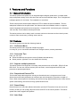
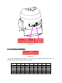
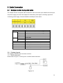
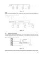
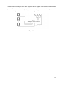
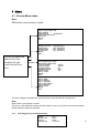
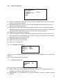
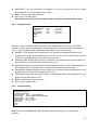
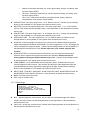
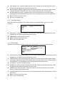
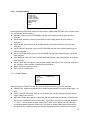
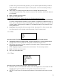
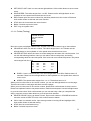
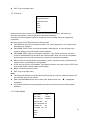
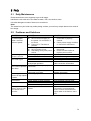
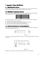
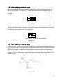
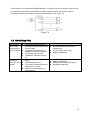
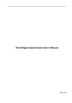
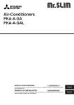
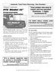
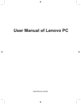
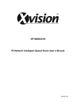
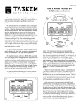
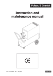
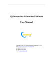
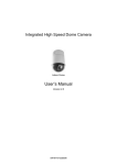
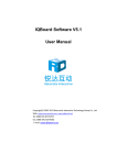
Optiview - OV23X Speed Dome User’s Manual Version 1.0 Table of Contents 1 FEATURES AND FUNCTIONS .................................................................................... 3 1.1 General Introduction .................................................................................................................................... 3 1.2 Features ........................................................................................................................................................ 3 1.2.1 On-Screen Menu ..................................................................................................................................... 3 1.2.2 On-screen Tips ........................................................................................................................................ 3 1.2.3 Support multiple protocols ...................................................................................................................... 3 1.2.4 Proportional Pan and Tilt......................................................................................................................... 3 1.2.5 Preset Setup ............................................................................................................................................ 3 1.2.6 Auto Scan ................................................................................................................................................. 3 1.2.7 Auto Pattern ............................................................................................................................................. 4 1.2.8 Auto Touring............................................................................................................................................. 4 1.2.9 Auto Flip ................................................................................................................................................... 4 1.2.10 Self-diagnosis ...................................................................................................................................... 4 1.2.11 Day/Night Mode (B/W & Color Mode)................................................................................................ 4 1.2.12 Auto Focus........................................................................................................................................... 4 1.2.13 Backlight Compensation ..................................................................................................................... 4 1.2.14 Pan Tilt and Zoom ............................................................................................................................... 4 1.2.15 3D Intelligent Location ........................................................................................................................ 4 1.2.16 Idle Motion ........................................................................................................................................... 5 1.2.17 Image Flip ............................................................................................................................................ 5 1.3 Specifications ............................................................................................................................................... 5 1.3.1 Technical Specifications.......................................................................................................................... 5 1.3.2 Performance Specifications .................................................................................................................... 6 2 ADDRESS, BAUD RATE AND PARITY SETUP .......................................................... 7 2.1 Address, Baud Rate and Parity Setup ........................................................................................................ 7 2.2 Set address dial switch ................................................................................................................................ 8 ii 3 CABLE CONNECTION ............................................................................................... 10 3.1 Multiple-function Composite Cable ........................................................................................................... 10 3.1.1 System Layout ....................................................................................................................................... 10 3.1.2 Keyboard Connection ............................................................................................................................ 11 4 MENU ......................................................................................................................... 13 4.1 Screen Menu Index .................................................................................................................................. 13 4.1.1 Self-diagnosis System Information ........................................................................................................... 13 4.1.2 Main Menu .............................................................................................................................................. 14 4.2 Menu Operation ........................................................................................................................................ 14 4.2.1 System Information................................................................................................................................ 15 4.2.2 Display Setting ....................................................................................................................................... 16 4.2.3 Camera Setting ...................................................................................................................................... 16 4.2.4 Function Setting ..................................................................................................................................... 20 4.3 Dome Abnormal Phenomenon Operation............................................................................................ 25 4.3.1 Restore to Factory Default Setup ......................................................................................................... 25 4.3.2 PTZ Movement is not smooth ............................................................................................................... 25 5 FAQ ............................................................................................................................ 26 5.1 Daily Maintenance .................................................................................................................................... 26 5.2 Problems and Solutions ......................................................................................................................... 26 6 APPENDIX Ⅰ THUNDER PROOF AND SURGE PROTECTION................................. 27 7 APPENDIX Ⅱ ABOUT RS485 BUS ............................................................................ 28 7.1 RS485 Bus Main Feature .......................................................................................................................... 28 7.2 RS485 Bus Transmission Distance .......................................................................................................... 28 7.3 Connection Methods and Terminal Resistance ....................................................................................... 28 iii 7.4 The Problem in Practical Use.................................................................................................................... 29 7.5 The Problem in Practical Use.................................................................................................................... 29 7.6 RS485 Bus FAQ ......................................................................................................................................... 30 8 APPENDIX TOXIC OR HAZARDOUS MATERIALS OR ELEMENTS ........................ 31 iv Welcome Thank you for purchasing our product! This user’s manual is designed to be a reference tool for the operation of your system. Here you can find information about this speed dome features and functions, as well as a detailed menu tree. Please keep it well for future reference! Before installation and operation, please read the following safeguards and warnings carefully! Important Safeguards and Warnings 1.Electrical safety All installation and operation here should conform to your local electrical safety codes. We assume no liability or responsibility for all the fires or electrical shock caused by improper handling or installation. We are not liable for any problems caused by unauthorized modification or attempted repair. 2.Transportation Security No heavy stress, violent vibration or water splash are allowed during transportation, storage and installation. Please use the original packing material (or the material of the same quality) when you ship it back to the manufacturer. 3.Installation/Unstallation Do not apply power to the product before completing installation. Do not put object on the product. Do not unscrew screws or housing, please contact qualified professionals to maintain. 4.Environment This series product should be installed in a cool, dry place away from direct sunlight, inflammable, explosive substances and etc. Please keep the sound ventilation. Do not allow the water and other liquid falling into the device, (IP67) Do not shoot light object, no matter the dome is in use or not, or the image may be blur or unclear. 2 1 Features and Functions 1.1 General Introduction This series speed dome product is an integrated high intelligent speed dome. It adopts water drop configuration design for the first time and has small and delicate shape. This is a digital and intelligent product of vivid video. The installation is convenient. These series product external ports adopt the PTZ to realize the quick installation. There is waterproof interface for the pipe thread. All of these make the installation easier. It supports various languages and protocol auto recognition. It supports 360°continuously pan, 92°tilt and 180°auto flip. It can realize no blind spot monitor. This series product can be widely used in remote monitor environment such as electric power, customs, water conservancy, banking sector and etc. 1.2 Features This series speed dome has the following features: 1.2.1 On-Screen Menu This series product menu supports multiple languages. It is easy for you to view dome information and configure dome, camera parameters. 1.2.2 On-screen Tips Here you can view: Preset number/title and system version (Software and hardware) Dome position. (Optional. You can disable this function) 1.2.3 Support multiple protocols This series speed dome supports universally used protocols such as DH-SD1, PELCO-P and PELCO-D. You can use various devices (such as matrix, control keyboard and DVR) and protocols to operate speed dome. 1.2.4 Proportional Pan and Tilt This function keeps the image from moving too fast when there is a large amount of zoom. Speed dome continually decreases or increases pan and tilt speeds in proportion to depth of zoom. When zooms speed is increasing, the camera moving speed becomes slow. When zooms speed is decreasing, the camera moving speed becomes fast. 1.2.5 Preset Setup Preset function is to save the address information (such as PTZ pan/tilt, focus and etc) to the memory so that you can quickly adjust the dome and PTZ to the correct position. This series speed dome max supports 255 presets. 1.2.6 Auto Scan 3 Camera scans back and forth regularly in a horizontal field. Here you need to set left and right limit and scan speed. You can set 5 scanning paths. 1.2.7 Auto Pattern Memorize dome operation such as pan, tilt, and zoom to repeat. Focus and iris are in auto mode during auto pattern. For each pattern, the time should be less than 60 seconds. You can set 5 pattern paths. 1.2.8 Auto Touring Add addresses into a routine in a desired order and then set time and stop duration for each address. The dome will begin an auto touring between these addresses. You can set 8 touring paths. 1.2.9 Auto Flip As long as you continue to hold the keyboard joystick in the down position, the dome rotates 180 degrees and repositions itself for uninterrupted viewing of any subjects that passes directly beneath the dome. 1.2.10 Self-diagnosis There is a self diagnosis procedure when dome boots up. Tilt and vertical engine check Camera diagnostics Display dome information and diagnosis information such as address, protocol, baud rate, type. 1.2.11 Day/Night Mode (B/W & Color Mode) System supports auto/manual switch in low illumination. In the auto mode, the camera can automatically switch the CCD level according to the light change. In the manual mode, it can use the menu or the button to realize the color display, black and white display, 1.2.12 Auto Focus Auto focus allows the lens to remain in focus during zoom-in, zoom-out and motion functions to get vivid image. You can use FAR or NEAR button to adjust focus manually. 1.2.13 Backlight Compensation Balance the brightest and darkest sections of a scene to make a more vivid picture. 1.2.14 Pan Tilt and Zoom Supports zoom in and zoom out during tilt and pan movement. In this period focus and iris are both in auto mode to get vivid image. 1.2.15 3D Intelligent Location Working with DVR, just click part of the current scene will be displayed in the central window and automatically zooms. All of these allow you to trace precisely. 4 1.2.16 Idle Motion When there is no available order, you can use menu to set dome idle status after specified duration. The idle status includes turn to specified preset or go to scan, tour or pattern function. 1.2.17 Image Flip You can enable image flip in the menu. The flip function meets more applicable requirements. 1.3 Specifications 1.3.1 Technical Specifications Power Camera Driver Consumption Heater Consumption Decoder Engine Preset Auto Tour Auto Pattern Auto Scan Information Lens Auto Rotation Auto Pan Manual Pan Motion Speed Preset Maximum Speed Manual Tilt Motion Manual Tilt Scan Section Control Port Baud Rate PTZ Scan Accuracy Signal Format S/N Ratio Effective Pixel Horizontal Resolution Fan Humidity Environment AC 24V/1.5A(±20%)(Includes temperature control circuit) 11W 12W Built-in stepper motor 255( in PELCO protocol) 8 5 5 Position, dome title, dome coordinates, and etc. Adjust speed in accordance with lens Tilt 92ºauto rotates to pan 180 º 0 º-360ºcontinuously 0.1º—300º/S 60 º~400º/s. There are 16-level. You can set from the menu. 0.1º—120º/S 0º—180º RS485 BUS 1200/2400/4800/9600 (Optional) 0.06 ± 0.015º PAL/NTSC (Camera mode) > 50dB 768(H)*494(V) / 795(H)*596(V) 480TVL/540TVL/700TVL Fan works continuously, heater auto controls (auto on when the temperature under 5℃) <90% -40℃—60℃(Outdoor) 5 1.3.2 Performance Specifications All digital design. All data are in the connection board. No data loss when power off occurs. Built-in Decode Built-in PTZ Built-in zoom lens, high sensitive, high resolution integrated digital process color camera. Fine stepper driver, stable performance, react quickly, precisely positioning. Integrated design, tight structure. Elegant mechanical driver device. Support 360 degrees continuous rotation, no monitor blind spot. 0.1°/s rotation speed while maintain stable image. 180 degrees tilt continuous monitor. Auto focus Auto iris control Auto brightness control Auto white balance Auto day/night switch OSD Integrated design, high stability. This speed dome max support 255 presets. Support 8 auto touring. Each touring max has 32 presets. 5 auto scan. 5 auto pattern. Each pattern can max support 400 commands and the interval shall be less than 60s. Built-in direction indicator. Built-in various adjustable protocols, baud rate RS485 BUS control Preset title display View dome initial setup information Modify camera parameter Set preset Set auto scan Set auto pattern Set auto day/night switch (Auto B/W & color switch) 6 2 Address, Baud Rate and Parity setup Before you operate, you need to set address, baud rate and parity. Otherwise you can not control the product! 2.1 Address, Baud Rate and Parity Setup Please configure the following settings before begin controlling dome: Address Baud rate Parity Note: Please reboot the speed dome to get all the setups activated! Please note this series speed dome can automatically recognize the DH-SD, PELCO-D. PELCO-P. Baud rate settings Please refer to the table below for detailed information. 1 2 Baud rate OFF OFF 9600bps ON OFF 4800bps OFF ON 2400bps ON ON 1200bps Table 2-1 Parity settings Please refer to the table below for detailed information. 3 4 Parity OFF OFF NONE ON OFF EVEN OFF ON ODD ON ON NONE Table 2-2 7 Figure 2-1 2.2 Set address dial switch Figure 2-2 The encode mode adopts binary system. 1 to 8 is valid bit. The highest address bit is 255. You can refer to the following sheet for more information. Address 1 2 3 4 5 6 7 8 1 1 2 3 4 5 6 OFF ON OFF ON OFF ON OFF OFF OFF ON ON OFF OFF ON OFF OFF OFF OFF ON ON ON OFF OFF OFF OFF OFF OFF OFF OFF OFF OFF OFF OFF OFF OFF OFF OFF OFF OFF OFF OFF OFF OFF OFF OFF OFF OFF OFF OFF OFF OFF OFF OFF OFF OFF OFF 8 7 8 …… 254 255 ON OFF ON ON OFF OFF OFF OFF OFF OFF OFF ON OFF OFF OFF OFF ………………………………………………………………… OFF ON ON ON ON ON ON ON ON ON ON ON ON ON ON ON 9 3 Cable Connection 3.1 Multiple-function Composite Cable The multiple-function composite cable includes the video connection port, RS485 connection port, and power-supply port, which are adopted for transmitting video signal, controlling signal and connecting power-supply. Connect RS485 to the 485 port of the dome. Name 485 VIDEO A Function 485-A. It is to control dome built-in PTZ. B 485-B. It is to control dome built-in PTZ. GND Ground. GND Ground port. OUT Video output port. Name AC24V Function 24V power port. Connect to the power cable. EARTH Ground port. AC24V 24V power port. Connect to the power cable. 3.1.1 System Layout The system installation layout is shown as below. 3.1.1.1 BUS connection Please refer to Figure 3-1 and Figure 3-2 for BUS cable connection. Figure 3-1 10 Figure 3-2 Note: Please use shielded twisted pair. The shielded layer shall connect to GND firmly; otherwise it may affect communication or video work. 3.1.1.2 Star Connection Please refer to Figure 3-3 for start connection information. Figure 3-3 3.1.2 Keyboard Connection This series dome supports keyboard operation. You can use keyboard to control the dome and PTZ. The display and control can work simultaneously. One keyboard can control maximum 255 speed domes. Please refer to Figure 3-4. Figure 3-4 Speed dome protocol is open and supports multiple popular system platforms in today’s market. 11 Please contact us freely if some matrix systems do not support dome camera communication protocol. The most direct and easy way is to use current system to process video signal and add some control keyboards to control speed dome. See Figure 3-5. Figure 3-5 12 4 Menu 4.1 Screen Menu Index Note: ERR means current setup is invalid. INITIAL INFORMATION… ADDR INFORMATION… SET NORTH LANGUAGE : ENGLISH FACTORY DEFAULT RESTART BACK EXIT PRESET TITLE AZIMUTH DISP POSITION ZOOM DISP TITLE DISP BACK EXIT : ON (ON/OFF) : ON (ON/OFF) : OFF (ON/OFF) : OFF (ON/OFF) : OFF (ON/OFF) SYSTEM INFORMATION DISPLAY SETTING CAMERA SETTING FUNCTION SETTING EXIT WB MODE : AUTO EXPOSURE SETTING DAY/NIGHT SETTING FOCUS MODE : AUTO FOCUS LIMIT : 30CM ZOOM SPEED : 08 DIGITAL ZOOM : OFF APERTURE : 09 NEXT PAGE BACK EXIT PRESET AUTO PAN AUTO SCAN AUTO CRUISE AUTO PATTERN IDLE MOTION NEXT PAGE BACK EXIT The above diagram illustrates the overall structure of the speed dome setup menu. Note: ERR means current setup is invalid. There may exist differences among various models in terms of function menu and parameters, please make the object as standard. 4.1.1 Self-diagnosis System Information ADDR BAUD RATE PARITY SOFTWARE :001-H :9600 :NONE :V1.00.0.R 13 After installation, please connect speed dome to power. The system goes on a self-diagnosis, and then it pops up the above interface to show the system information. If there is anything wrong during the self-diagnosis, system pops up error code. The above interface disappears after speed dome received the first command (or the display time lasts for 40 seconds.) ADDR: Here you can view dome address information. For example, 001-H, 1 is the address number, -H is hard address mode. –S is software address mode. BAUD RATE: Dome communication baud rate. PARITY: Communication parity bit format. SOFTWARE: Dome PTZ software version. Note: Please set the corresponding control information (address, baud rate and parity) of the dome in matrix, control keyboard and DVR before using these devices to directly control the dome. Please make sure all the cable connections are right. 4.1.2 Main Menu You can open the IP dome menu via control keyboard, matrix, or speed dome control terminal. SYSTEM INFORMATION DISPLAY SETTING CAMERA SETTING FUNCTION SETTING EXIT SYSTEM INFORMATION: Dome self-diagnosis information, address information, set north direction, language, factory default setup, reboot and so on. DISPLAY INFORMATION: Display dome preset title, azimuth display, direction and etc. CAMERA PARAMETERS: Display dome white balance setup, exposure setup, day/night setup, focus setup. FUNCTION SETTING : Set preset, pan, scan, cruise, pattern, idle motion. EXIT : Log out the system menu. 4.2 Menu Operation In the speed dome main menu, you can use the left/right button on the keyboard or in the speed dome terminal menu to configure the system menu. Before setup, please move the cursor to the current item you want to configure. In main menu, please click confirm button to go to the sub menu or use left/right key to configure setup. Use up/down button to select back option and then click confirm button to go back to the previous menu. Use up/down button to select exit option and then click confirm button to log out system menu. All setup here will not lose when encounter power failure. 14 4.2.1 System Information INITIAL INFORMATION ADDR INFORMATION SET NORTH LANGUAGE : ENGLISH FACTORY DEFAULT RESTART BACK EXIT INITIAL INFORMATION: Move the cursor to INITIAL INFORMATION and then click confirm button to go to the third submenu. ADDR INFORMATION: Move the cursor to SITE INFORMATION and then click confirm button to go to the third submenu. SET NORTH DIRECTION: Set dome benchmark direction so that you can know the angel between the benchmark and then current location. Please move the cursor to the option and then click confirm button until you see O.K. Now you have set north direction. LANGUAGE: The dome menu language. FACTORY DEFAULT: Restore dome factory default setup. Please move the cursor to the option and then click confirm button until you see O.K. Now you can see the IP dome begin rebooting to restore factory default setup. RESTART: Reboot the speed dome. BACK: Go back to the previous menu. EXIT: Log out system menu. 4.2.1.1 Initialization information ADDR BAUD RATE PARITY SOFTWARE BACK EXIT :001-H :9600 :NONE :V1.00.0.R Move the cursor to INITIAL INFORMATION and then click confirm button, you can see the above interface. Here you can view dome basic information. 4.2.1.2 Address Information ADDR TYPE ADDR-HARD ADDR-SOFT BACK EXIT : HARD : 001 : 001 Move the cursor to SITE INFORMATION and then click confirm button. ADDR TYPE: There are two options: soft and hard. Please use the left/right button on the keyboard or in the speed dome terminal menu to set. ADDR-HARD: It is an address you set in the dial switch. You can not modify it through software. 15 ADDR-SOFT: You can set address via software. It is to say, you can use menu to modify dome address. The value ranges from 1 to 254 BACK: Go back to the previous menu. EXIT: Log out system menu. Note: the dome needs to be rebooted in order to make the modified address valid. 4.2.2 Display Setting PRESET TITLE AZIMUTH DISP POSITION ZOOM DISP TITLE DISP BACK EXIT : ON : ON : OFF : OFF : OFF (ON/OFF) (ON/OFF) (ON/OFF) (ON/OFF) (ON/OFF) Move the cursor to DISPLAY SETUP and then click confirm button, you can go to the third submenu. Please use the left/right button on the keyboard or in the speed dome terminal menu to set. After completed setup, please click save button to save current setup. PRESET TITLE: Display dome preset title or not. Please use the left/right button on the keyboard or in the speed dome terminal menu to set. You can go to Function Setup->Preset section to set corresponding preset value and preset title. AZIMUTH DISP: Display dome current coordinates or not. Please use the left/right button on the keyboard or in the speed dome terminal menu to set POSITION: Display the angel between the benchmark and then current location. Please use the left/right button on the keyboard or in the speed dome terminal menu to set. ZOOM DISP: Display speed dome zoom speed or not. Please use the left/right button on the keyboard or in the speed dome terminal menu to set. TITLE DISP: Display the dome title. Please use the left/right button on the keyboard or in the speed dome terminal menu to set. BACK: Go back to the previous menu. EXIT: Log out system menu. 4.2.3 Camera Setting WB.MODE : AUTO ( ATW/OUTDOOR / INDOOR/OUTDOOR AUTO/NA LAMP AUTO/NA LAMP) EXPOSURE SETTING DAY/NIGHT SETTING FOCUS MODE :AUTO (AUTO/MANUAL) FOCUS LIMIT :30CM (1M/5M/15M/01CM/05CM/) ZOOM SPEED :08 (01~08) DIGITAL ZOOM : OFF (ON/OFF) APERTURE :09 (01~16) NEXT PAGE BACK EXIT Move the cursor to CAMERA SETTING and then click confirm button, you can go to the submenu. 16 WB MODE: Set white balance mode: auto/ATW/outdoor/indoor/outdoor auto/NA lamp auto/ NA lamp. Please use the left/right button on the keyboard or in the speed dome terminal menu to set. EXPOSURE SETTING: Move the cursor to current option and then click confirm button, you can go to the third menu. DAY/NIGHT SETTING: Set day/night mode. Move the cursor to current option and then click confirm button, you can go to the third menu. There are three options: auto/manual/off. Please use the left/right button on the keyboard or in the speed dome terminal menu to set. FOCUS MODE: There are two modes: Manual/Auto. Please use the left/right button on the keyboard or in the speed dome terminal menu to set. FOCUS LIMIT: Set the distance between lens and the object. (short focus distance will lead to a phenomena that the lens focuses on the housing) Meanwhile, you can change the focus speed by changing focus distance. Focus limit: 1cm/5cm/30cm/1m/5m/15m are optional, Please use the left/right button on the keyboard or in the speed dome terminal menu to set. ZOOM SPEED; The zoom speed value ranges from 1 to 8. The bigger the value, the faster the speed. Please use the left/right button on the keyboard or in the speed dome terminal menu to set. DIGITAL ZOOM: There are two options: on/off. Please use the left/right button on the keyboard or in the speed dome terminal menu to set. APERTURE: It is to adjust the lens to achieve clear video. The value ranges from 1 to 16. Please use the left/right button on the keyboard or in the speed dome terminal menu to set. NEXT PAGE: It includes the following options: picture flip, freeze function, camera factory default setup, camera restart. Please use the left/right button on the keyboard or in the speed dome terminal menu to set. BACK: Go back to previous menu. EXIT: Log out system menu. 4.2.3.1 Exposure Setting AE MODE GAIN SETTING SHUTTER IRIS SETTING EXPOSURE COM SLOW AE SLOW SHUTTER WDR ENABLE NEXT PAGE BACK EXIT :AUTO (MANUAL/IRIS PRIO/SHUT PRIO) :02 (01~16) :1/50 (1/3~1/10000) :11 (01~18) :08 (01~15) :01 (01~16) :ON (ON/OFF) :AUTO (AUTO/ON/OFF) AE MODE: Here you can set the camera exposure mode. It includes: auto/manual/IRIS PRIO / SHUT PRIO. Please use the left/right button on the keyboard or in the speed dome terminal menu to set. o Auto: It becomes valid after you set the exposure compensation, backlight compensation (BLC), slow shutter, wide dynamic region (WDR). 17 o Manual: It becomes valid after you set the gain setting, shutter, iris setting, wide dynamic region (WDR). o IRIS PRIO: It becomes valid after you set the exposure setting, iris setting, wide dynamic region (WDR). o SHUT PRIO: It becomes valid after you set the shutter setting, exposure compensation, wide dynamic region (WDR). GAIN SETTING: The value ranges from 1 to 16. Default value is 2. Please use the left/right button on the keyboard or in the speed dome terminal menu to set. SHUTTER: You can set shutter speed here. The value ranges from 1/3 to 1/10000. Default value is 1/50. Please use the left/right button on the keyboard or in the speed dome terminal menu to set. IRIS SETTING: The value ranges from 1 to 18. Default value is 11. Please use the left/right button on the keyboard or in the speed dome terminal menu to set. EXPOSURE COM: The value ranges from 1 to 15. Default value is 8. Please use the left/right button on the keyboard or in the speed dome terminal menu to set. SLOW AE: in the strong light environment, you can lower the camera exposure speed to capture the image and enhance the definition. The value ranges from 1 to 16. The bigger the value, the higher the exposure speed. Please use the left/right button on the keyboard or in the speed dome terminal menu to set. Please make sure your camera supports this function. SLOW SHUTTER: In lower illumination environment, you can lower the cameras auto exposure time to capture the image and enhance the definition. Please note for the moving object, the image trail phenomenon may occur. Please use the left/right button on the keyboard or in the speed dome terminal menu to set. WDR ENBALE: It is an abbreviation for wide dynamic region. Please make sure your camera supports current function. This function can adjust the video brightness when the contrast between the strong light and the dark light is too high. Please use the left/right button on the keyboard or in the speed dome terminal menu to set. NEXT PAGE: To set BLC, GAIN LIMIT, SLOW SHUTTER LIMIT, NOISE REDUCTION, 3D NOISE REDUCTION, BACK ,EXITand etc. Click OK button to display the above items. BACK: Go back to previous menu. EXIT: Log out system menu. 4.2.3.2 Next Page BLC :OFF (ON/OFF) GAIN LIMIT :08 (01~12) SLOW SHUTTER LIMIT :1/12 NOISE REDUCTION :03 (OFF~05) 3D NOISE REDUCTION :OFF (OFF~02) BACK EXIT BLC: Adjust brightness of the camera, the lens will auto compensate light to the object which in the dark. Please use the left/right button on the keyboard or in the speed dome terminal menu to set. Gain Limit: set the gain maximum limit. Please use the left/right button on the keyboard or in the speed dome terminal menu to set. 18 Slow Shutter Limit: set Slow Shutter Minimum Limit. Please use the left/right button on the keyboard or in the speed dome terminal menu to set. Noise Reduction: When it appears noise in the low illumination environment, digital-filtering could be resorted to decrease noise, thus to make the picture more vivid and clear. 3D Noise Reduction: When it appears noise in the low illumination environment, digitalfiltering could be resorted to decrease noise, thus to make the picture more vivid and clear. Back: Go back to previous menu. Exit: Log out system menu. 4.2.3.3 Day/Night Setting Move the cursor to DAY/NIGHT SETTING and then click confirm button, you can go to the submenu. DAY/NIGHT THRESHOLD: SAVE BACK EXIT : AUTO (AUTO /NIGHT/DAY) :5 (1~8) DAY/NIGHT: There are four options: auto/night/day. Please use the left/right button on the keyboard or in the speed dome terminal menu to set. THRESHOLD: set the sensitivity levels. BACK: Go back to previous menu. EXIT: Log out system menu. 4.2.3.4 Next Page Move the cursor to NEXT PAGE and then click confirm button, you can go to the submenu. PICTURE FLIP :OFF (ON/OFF) FREEZE FUNC :OFF (ON/OFF) AF SENS :NORMAL (NORMAL/LOW) STABLE :OFF (ON/OFF) CAMERA FACTORY DEFAULT CAMERA RESTART BACK EXIT PICTURE FLIP: This function allows you to flip image. Please use the left/right button on the keyboard or in the speed dome terminal menu to set. FREEZE FUNC: This function allows the system from one preset to another preset, without showing the video during the PTZ movement. There are two options: on/off. Please use the left/right button on the keyboard or in the speed dome terminal menu to set. AF SENS: To set focus sensitivity levels. STABLE: To reduce the effect of dither on the image. Please use the left/right button on the keyboard or in the speed dome terminal menu to set. CAMERA FACTORY DEFAULT: Move the cursor to current item and then click confirm button to restore factory default setup. CAMERE RESTART: Move the cursor to current item and then click confirm button to reboot the camera. BACK: Go back to previous menu. EXIT: Log out system menu. 19 4.2.4 Function Setting PRESET AUTO PAN AUTO SCAN AUTO CRUISE AUTO PATTERN IDLE MOTION NEXT PAGE BACK EXIT Please go back to main menu and move the cursor to FUNCTION SETTING, click confirm button. You can see the above interface. PRESET: Move the cursor to PRESET and then click confirm button to go to the third submenu. AUTO PAN: Move the cursor to PAN and then click confirm button to go to the third submenu. AUTO SCAN: Move the cursor to SCAN and then click confirm button to go to the third submenu. AUTO CRUISE: Move the cursor to AUTO CRUISE and then click confirm button to go to the third submenu. AUTO PATTERN: Move the cursor to PATTERN and then click confirm button to go to the third submenu. IDLE MOTION: Move the cursor to IDLE MOTION and then click confirm button to go to the third submenu. NEXT PAGE: Set PTZ speed, initial position settings, idle motion, PTZ auto stop, back and etc. functions. Click ok button to display the above items. BACK: Go back to previous menu. EXIT: Log out system menu. 4.2.4.1 Preset Setup PRESET NO. : 001 TITLE : PRESET 001 SETTING CALL BACK EXIT Move the cursor to PRESET button and then click confirm button to go to set interface. PRESET NO: Please use left/right key to modify preset number. The value ranges from 1 to 255. TITLE: Title text is the label used for you to identify the camera. System will automatically name a title for the camera. SETTING: Please input preset number first and then select the monitor zone. Please move the cursor to setting and click confirm button. The system will pop up a message: PRESET: ***. Here *** means preset number. And the SETTING column pops up an OK. Now you successfully added a preset. Please note, you need to enable display preset title function first (Main menu->display setting->preset title).Repeat the above procedures to set more 20 presets. Once you want to modify a preset, you can input the preset number you want to modify and then follow the above steps to set the preset. You can successfully modify a preset content. CALL: Here is to recall preset. Move the cursor to PRESET NO and then input corresponding preset value. Then move the cursor to CALL and then click confirm button to go to a preset. BACK: Go back to previous menu. EXIT: Log out system menu. For PELCO protocol user, please refer to the following special functions: Call preset: Call preset 28 or preset 95 to go to dome menu. Call preset 29 or preset 99 to go to scan. Call preset 24 or preset 81 to go to pattern. Call preset 25 or preset 82 to go to cruise (tour). Call preset 30 or preset 96 to stop scan or pattern. Call preset 31 or preset 83 to begin rotation. Call preset 33 to enable PTZ 180 degrees rotation. Call preset 34 to set dome position as 0. Set preset: Set preset 26 or 92 to set scan left limit. Set preset 27 or 93 to set scan right limit. Set preset 22 or 79 to begin record. Set preset 23 or 80 to stop record. 4.2.4.2 Pan PAN SPEED RUN STOP BACK EXIT :181 Move the cursor to PAN button and then click confirm button to go to setup interface. PAN SPEED: Set dome rotation speed. The Value ranges from 1 to 255. Please use the left/right button on the keyboard or in the speed dome terminal menu to set. RUN: Move the cursor to call item and then click confirm button. The dome begins 360 degrees continuous rotation. STOP: Highlight stop item and then click confirm button. The dome stops rotation. BACK: Go back to previous menu. EXIT: Log out system menu. 4.2.4.3 Scan SCAN NO. : 001 SET LEFT LIMIT SET RIGHT LIMIT SCAN SPEED: 161 RUN STOP BACK EXIT Move the cursor to SCAN button and then click confirm button. SCAN NO: Here is to set auto scan number. The value ranges from 1 to 5. Please use the left/right button on the keyboard or in the speed dome terminal menu to set. SET LEFT LIMIT: Here is to set camera left address. Click confirm button to save current setup. 21 SET RIGHT LIMIT: Here is to set camera right address. Click confirm button to save current setup. SCAN SPEED: The value ranges from 1 to 255. Please use the left/right button on the keyboard or in the speed dome terminal menu to set. RUN: Please input auto scan number first, and then please move the cursor to RUN and click confirm button to activate auto scan function. STOP: Here is to terminate auto scan function. BACK: Go back to previous menu. EXIT: Log out system menu. 4.2.4.4 Cruise (Touring) CRUISE NO: : 001 CRUISE SETTING DELETE CRUISE RUN STOP BACK EXIT Move the cursor to highlight CRUISE item and then click confirm button to go to set interface. CRUISE NO :Here is to ser tour number. The value ranges from 1 to 8. Please use the left/right button on the keyboard or in the speed dome terminal menu to set. CRUISE SETTING: Move the cursor to cruise setting item and then click confirm button. You can see the following interface. Here you can add or remove the preset, and set the corresponding dwell time and call speed. One cruise can max include 32 presets. The preset value ranges from 0 to 200. NO 01 02 03 … 32 PRESET DWELL 000 005 000 005 000 005 … … 000 005 SPEED 013 013 013 … 013 DWELL: Here is t set dwell time. The value ranges from 3s to 255s. Default value is 5 seconds. Please use the left/right button on the keyboard or in the speed dome terminal menu to set. SPEED: The speed value ranges from 1 to 16. The default value is 13. When you move the cursor to one cruise number, you can use left/right button to turn the page. There are 8 cruises in each page and there are total 4 pages. When you move the cursor to one cruise number, please click confirm button to set the cruise. Please use up/down button to set preset number, dwell time and speed. Use the left/right button to go to the next cruise. Click confirm button you can exit the setup. After you completed the setup, move the cursor to back button to go to the previous interface. DELETE CRUISE: Here is to delete a cruise. Input cruise number in CRUISE NO and then move the cursor to DELETE cruise, click confirm button to delete. CALL: Here is to activate cruise. Input touring number in touring NO and highlight CALL, click confirm button to activate touring. STOP: Here is to terminate touring. BACK: Go back to previous menu. 22 EXIT: Log out system menu. 4.2.4.5 Pattern PATTERN NO: 001 PROGRAM START PROGRAM STOP RUN STOP BACK EXIT Pattern function can memory PTZ operation and camera focus zoom in and zoom out. From the start position, dome begins auto movement repeatedly. This series IP dome supports maximum 5 patterns and one pattern can max support 400 commands. Move the cursor to PATTERN and click confirm button. PATTERN NO: Here is to set pattern number. The value ranges from 1 to 5. Please click left/right key to configure. PROGRAM START: Here is to memorize pattern starting point. An icon OK pops up in screen to prompt you system begins memory pattern. PROGRAM STOP: Here is to set pattern stop point. After all the movement, move the cursor to PROGRAM STOP and then click confirm button. Now you have set one pattern. System pops up an icon OK to prompt you system has memories one pattern. RUN: Here is to activate pattern. Input pattern number, move the cursor to RUN and click confirm button, system begins running pattern. STOP: Here is to stop current pattern. Input pattern number, move the cursor to STOP and click confirm button. System stops current pattern. BACK: Go back to previous menu. EXIT: Log out system menu. Note: The dwell time between two orders should be less than one minute, otherwise system will set to default value as one minute. After click PROGRAM STOP, do not click CALL button before icon “●” disappears completely. Any manual operation during the pattern procedure will terminate current dome pattern operation. 4.2.4.6 Idle Motion IDLE FUNC : OFF IDLE TIME : 001MIN IDLE ACTION : PRESET PRESET NO :001 AUTO SCAN NO :001 CRUISE NO :001 PATTERN NO :001 SAVE BACK EXIT 23 When there is no available command for specified time, dome automatically goes on the previous set functions. IDLE FUNCTION :There are two modes ON/OFF. Please use left/right key to set. IDLE TIME: System idle period. The value ranges from 1 to 720 minutes. Please use the left/right button on the keyboard or in the speed dome terminal menu to set. IDLE ACTION:There are several functions you can select: NONE/PRESET/SCAN/ CRUISE /PATTERN. Please use the left/right button on the keyboard or in the speed dome terminal menu to set. PRESET NO: Here is for you to set preset number. The value ranges from 1 to 255. System goes to specified preset when idle status is on. AUTO SCAN NO: The value ranges from 1 to 5. Please use the left/right button on the keyboard or in the speed dome terminal menu to set. System begins specified scan when idle status is on. CRUISE NO: The value ranges from 1 to 8. Please use the left/right button on the keyboard or in the speed dome terminal menu to set. System begins specified touring when idle status is on. PATTERN NO:The value ranges from 1 to 5. Please use the left/right button on the keyboard or in the speed dome terminal menu to set. System begins specified pattern when idle status is on. SAVE:Move the cursor to SAVE and click confirm button to save current setup. BACK: Go back to previous menu. EXIT: Log out system menu. 4.2.4.7 Next Page PTZ SPEED :4 (1~5) SET ZERO POWER UP MENU IDLE :1M (1M/2M/3M/4M/5M/OFF) PTZ AUTOSTOP :15S (5S/10S/15S/20S/25S/30S/OFF) BACK EXIT Move the cursor to the Next Page and click OK button to see the above interface. PTZ Speed: set dome PTZ speed. Range: 1~5. Please use the left/right button on the keyboard or in the speed dome terminal menu to set. SET ZERO: Click ‖OK‖ button after PTZ debugged to the initial position Power Up: actions such as ―None/Auto/Preset/Scan/Tour/Pattern‖ are optional. Please use the left/right button on the keyboard or in the speed dome terminal menu to set. MENU IDLE: 24 a. when this item is not ―off‖ and the menu is open, it will auto exit the menu in a certain period of time if there is no operations to the menu. b. Off/1/2/3/4/5 Minute are optional. Off: always display the dome menu. Please use the left/right button on the keyboard or in the speed dome terminal menu to set. PTZ AUTOSTOP: a. PTZ auto stops relevant motions in the specified time. b. Off/5s/10s/15s/20s/25s/30s are optional. Please use the left/right button on the keyboard or in the speed dome terminal menu to set. Back: Go back to previous menu. Exit: Log out system menu. 4.3 Dome Abnormal Phenomenon Operation 4.3.1 Restore to Factory Default Setup From main menu-> SYSTEM INFORMATION, move cursor to FACTORY DEFAULT and click confirm button. Dome will reboot and all the setups restore to factory default setup. 4.3.2 PTZ Movement is not smooth From menu to SYSTEM INFORMATION, move cursor to RESTART and click confirm button. This reboot will not modify all activated setup (such as preset, tour and pattern) 25 5 FAQ 5.1 Daily Maintenance Please clean dome cover regularly to get vivid image. Handle the cover with care. Use water to wash. Don’t use cloth to clean. Use mild detergent to clean if there is too much dust. Note: The sweat from your hand may erode plating surface, your nail may scrape dome cover result in blur image. 5.2 Problems and Solutions SYMPTOM No self-diagnosis, no video signal when I connect dome to power. No self diagnosis. There is a noise Self diagnosis is ok. No video signal Self diagnosis is o.k. but I can not operate the dome. Video signal loss occurs in high speed rotation. Video signal is not successive Video is not clear. During camera switch, there is a tilt movement in the monitor. CAUSE Red LED is not on. 24V AC does not apply to the power. Or connection is too loose. Power off or Transformer problem. Red LED light is on 24V AC power is low Something wrong with power socket. Power supply is inadequate. Mechanical malfunction. Power connection is too loose. Check the circuit connection. Video switch connection is wrong or improper operation. Control circuit is not properly connected SOLUTION Check 24V AC power is connected or properly earthed. Check power supply condition or check 24V transformer. Dome address, protocol or baud rate setup is not right. Power supply is not sufficient Please refer to user’s manual for detailed information. Replace power socket. Circuit connection is too loose. Video switch or power problem Focus is in manual mode. Dome cover is dirty. Camera power is not in the same Phase. Connect tightly. Need electrical engineer help. Control manually. Wash dome cover When several domes are connected to one transformer, please connect the transformer output cable to the domes’ same side. Use multimeter to check dome load. Please contact retailer to replace power socket. Replace power socket. Need electrical engineer help. connect tightly Connect again Please refer to user’s manual for cable connection information. check control cable connection. 26 6 Appendix Ⅰ Thunder Proof and Surge Protection This series speed dome adopts TVS lighting protection technology. It can effectively prevent damages from various pulse signals below 1500W, such as sudden lighting and surge. While maintaining your local electrical safety code, you still need to take necessary precaution measures when installing the speed dome in the outdoor environment. The distance between the signal transmission cable and high-voltage device (or high-voltage cable) shall be at least 50 meters. Outdoor cable layout shall go under the penthouse if possible. For vast land, please use sealing steel tube under the land to implement cable layout and connects one point to the earth. Open floor cable layout is forbidden. In area of strong thunderstorm hit or near high sensitive voltage (such as near high-voltage transformer substation), you need to install additional high-power thunder protection device or lightning rod. The thunder protection and earth of the outdoor device and cable shall be considered in the building whole thunder protection and conform to your local national or industry standard. System shall adopt equal-potential wiring. The earth device shall meet anti-jamming and at the same time conforms to your local electrical safety code. The earth device shall not short circuit to N (neutral) line of high voltage power grid or mixed with other wires. When connect the system to the earth alone, the earth resistance shall not be more than 4Ω and earth cable cross-sectional area shall below 25 mm2. See Figure 6-1. Figure 6-1 27 7 Appendix Ⅱ About RS485 Bus 7.1 RS485 Bus Main Feature RS485 is semi duplex communication cable of impedance 120Ω . Its max load amount is 32 effective loads (including main control device and devices to be charged). 7.2 RS485 Bus Transmission Distance When we take 0.56mm (24AWG) twisted-pair as communication cable, the max transmission distance (theoretically) are listed below (according to different baud rates). Baud Rate Max Distance 2400 BPS 1800M 4800 BPS 1200M 9600 BPS 800M In the following situations, the max transmission distance shall become shorter accordingly: The communication cable is a little bit thin; The surrounding environment has strong electromagnetic interference; There are too much devices connected to the RS485 bus; And vice versa, the max transmission distance shall become longer. 7.3 Connection Methods and Terminal Resistance 1) RS485 bus requires all devices use the following connection methods. Both terminals shall have 120Ω resistance. See Figure 7-1. Figure 7-1 Or you can refer to for the simplified way as in Figure 7-2. But the distance between ―D‖ shall not exceed 7M. Figure 7-2 2) Please refer to chapter 2.1 for 120Ω resistance information on the main board. 28 7.4 The Problem in Practical Use There are 120Ω device terminal resistance in power socket. There are two connection ways. The first one is shown as in Figure 7-3. It is the factory default connection method. Now the jumper caps (connection board) are connected to the second and third socket, the 120Ω has not connected. 1 2 3 J6 Default jumper setup (120Ω resistance has not connected) Figure 7-3 If you want to connect to the 120Ω resistance, you can remove the jumper caps from the second and the third socket and then insert them to the first and second socket respectively. See Figure 7-4. Now you has connected to the 120Ω resistance. 1 2 3 J6 Jumper setup(Connect to 120Ω resistance) Figure 7-4 7.5 The Problem in Practical Use In practical usage, we usually adopt star type connection. The terminal resistance shall connect to the furthest two devices (Such as device 1# and device 15# in Figure 7-5 ). But this connection way does not conform to RS485 Bus standard. When the distances between devices are too long, the signal reflection occurs and anti-jamming decreases, thus the signal reliability becomes very low. You can see speed dome is not under control or speed dome is running automatically and can not stop. Figure 7-5 29 In this situation, we recommend RS485 distributor. This device can turn star type connection into the connection that conforms to RS485 bus industry standard, which can avoid the above mentioned problems and enhance communication reliability. See Figure 7-6. Figure 7-6 7.6 RS485 Bus FAQ Phenomenon Speed dome can run selfdiagnosis but I can not control it. I can control the speed dome but is not smooth Possible Reasons Host address(baud rate) and speed dome address(baud rate) are not match; Positive and negative end of RS485 Bus are misconnected; Connection cable is loose; RS485 Bus connection are cut off; RS485 Bus connection are not good; One RS485 bus is off; The distance between host and speed dome is too far; Parallel connected too much speed domes. Solution Modify host or speed dome setup ; Switch RS485 positive end and negative end; Fix connection cable firmly; Replace RS485 Bus. Connect RS 485 Bus again; Replace RS485 Bus; Add terminal matching resistance; Add RS485 distributor. 30 8 Appendix Toxic or Hazardous Materials or Elements Toxic or Hazardous Materials or Elements Component Name Sheet Metal Pb Hg Cd Cr VI PBB PBDE ○ ○ ○ ○ ○ ○ ○ ○ ○ ○ ○ ○ ○ ○ ○ ○ ○ ○ ○ ○ ○ ○ ○ ○ ○ ○ ○ ○ Plastic Parts PCB Housing Camera Driver Bearing ○ Connection Cable Motor (If possible) Power (If possible) Bracket (If possible) Accessories ○ Note O: Indicates that the concentration of the hazardous substance in all homogeneous materials in the parts is below the relevant threshold of the SJ/T11363-2006 standard. X : Indicates that the concentration of the hazardous substance of at least one of all homogeneous materials in the parts is above the relevant threshold of the SJ/T11363-2006 standard. 31 Note This manual is for reference only. Slight difference may be found in the user interface. All the designs and software here are subject to change without prior written notice. If there is any uncertainty or controversy, please refer to the final explanation of us. Please visit our website or contact your local service engineer for more information. 32