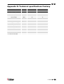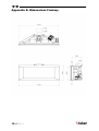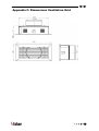
1
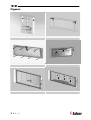
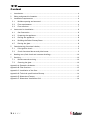
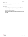
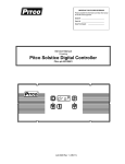
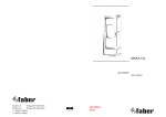
Fantasy 40010638 - 0742 UK Installation Guide IRL UK IRL Figures 1 B B A 2 B A B A C C C A 3 4 D D D 5 1<<<< 6 UK IRL Figures F E 7 8 G G G G G G 9 E 10 >>>>2 UK IRL Content 1 Introduction ......................................................................................... 4 2 Safety and general information .................................................................. 5 3 Installation requirements ......................................................................... 6 4 5 3.1 Builders opening and surround ............................................................. 6 3.2 Flue requirements............................................................................ 6 3.3 Flue restrictor ................................................................................ 7 Instruction for Installation ........................................................................ 8 4.1 Gas Connection ............................................................................... 8 4.2 Preparing the appliance..................................................................... 8 4.3 Placing the appliance........................................................................ 8 4.4 Building the False Chimney Brest.......................................................... 8 4.5 Placing the glass.............................................................................. 8 Commissioning (functional checks) .............................................................. 9 5.1 Pilot ignition check .......................................................................... 9 5.2 Check functional burner and pilot burner................................................ 9 6 Handing over (final check and customer briefing) ........................................... 10 7 Servicing ............................................................................................ 10 7.1 Routine annual servicing ................................................................... 10 7.2 Cleaning the glass ........................................................................... 10 Appendix A: Example calculation..................................................................... 11 Appendix B: Flue restrictor............................................................................ 12 Appendix C: Installation of the flue.................................................................. 13 Appendix D: Technical specifications Fantasy...................................................... 14 Appendix E: Dimensions Fantasy...................................................................... 15 Appendix F: Dimensions Ventilation Grid ........................................................... 16 3<<<< UK IRL 1 Introduction Note: these instructions should be read carefully and retained for future reference. Please leave these instructions with the user. Special features: • Room sealed appliance, inlet and outlet are led to the outside using a natural draught concentric pipe system (100 mm/150 mm) (no power fan required). • Air supply and flue-gases go to outside atmosphere through wall or roof. A maximum horizontal extension of 6 meters is possible. • Remote Control standard on both models. • Meets the requirements of the European Gas Appliance Directive (GAD) and carries the CE mark. >>>>4 UK IRL 2 Safety and general information Before installation, ensure that the local distribution conditions (identification of the type of gas and pressure) and the adjustment of the appliance are compatible. This gas appliance is factory set and can not be adjusted. This appliance does not contain any component manufactured from asbestos or any asbestos related products. The pilot and flame sensing device fitted to this fire is also a safety device. If for any reason any part of the pilot assembly is to be replaced, the entire assembly, including the pilot burner, thermocouple, electrode and injector, must be exchanged complete for a pilot assembly from the original manufacturer only. Ventilation This appliance is room-sealed and doesn't require purpose provided ventilation. Never use the appliance if it has a broken glass. General safety It is the law in the UK that all gas appliances, are installed by a competent person in accordance with the Gas Safety (Installation and Use) Regulations (as amended), the relevant British Standards for Installation work, Building Regulations, Codes of Practice and the manufacturers instructions. Always use an additional guard if there are elderly, infirm or children in the same room of the appliance. The installation should also be carried out in accordance with the following where relevant: • BS5871 Part1; • BS5440 Parts 1 & 2; • BS1251; • Building Regulations Document J (as applicable); • Building Regulations and Standards issued as relevant by the Department of the Environment or the Scottish Development Department; • In the Republic of Ireland installation should be carried out in accordance with IS813, ICP3, IS327, Building Regulations, Codes of Practice, the manufacturers instructions and all other regulations in force. Failure to comply with the above could leave the installer liable to prosecution and invalidate the appliance warranty. 5<<<< UK IRL 3 Installation requirements Note: Since the appliance is a source of heat, circulation of air occurs. Therefore it is of importance that you do not use the appliance shortly after a renovation of the home. Due to the natural circulation of air, moist and volatile components from paint, building materials, carpet etc. will be attracted to the lit appliance. These components can settle onto cold surfaces in the form of soot. As on all heat producing appliances, soft furnishings such as blown vinyl wallpaper placed too near the appliance may become scorched or discoloured. This should be born in mind when installing the appliance. 3.1 Builders opening and surround The appliance can be installed in a non-combustible fireplace or a builders opening. This could be either an existing builders opening or a new made prefab builders opening. In both cases keep the following in mind: • the (false) chimney breast has to be made of non-combustible material (e.g. Promatect); • See Appendix E for dimensions of the appliance; • always ventilate the space above the appliance. Use the included Faber ventilation grids; • to avoid cracking, the plaster has to dry for at least 1 day per millimetre plaster; • to avoid discolouring the plaster has to be heat resistant to min. 100 °C. 3.2 Flue requirements The appliance is of the type C11/C31. The appliance will need to be supplied with the approved Faber flue pipes and terminal, it is not possible to supply your own. The minimum effective height of the flue system must be 1 meter. Flue routing: • a horizontal extension with elbows is allowed for a maximum of 6 meter. • vertical max. 12 meters (without horizontal extensions only). Determine with the help of appendix A, B and C if the desired routing is possible. To establish this you will need to calculate: The effective height (this is the real difference in height between the upper side of the appliance and the terminal). The total horizontal extension. This is the total horizontal flue length where: 1. each 90-degree bend, which is in the horizontal area, counts for 2 meter; >>>>6 UK IRL 2. each 45-degree bend, which is in the horizontal area, counts for 1 meter; 3. elbows and bends at the transition from horizontal to vertically are not to be counted; 4. the wall mounted terminal counts for 1 meter. 3.3 Flue restrictor If applicable, in the table of appendix B is also stated the size of a flue restrictor. This restrictor needs to be fitted in the combustion chamber when placing the appliance. Normally the smallest flue restrictor is fitted at production. 7<<<< UK IRL 4 Instruction for Installation 4.1 Gas Connection Installation pipes should be in accordance with BS 6891. Pipe work from the meter to the appliance must be of adequate size. The complete installation including the meter must be tested for soundness and purged as described in the above code. A means of isolation must be provide in the supply to facilitate servicing. The connection should be made in 8 mm copper or similar semi flexible tube. (max 1 meter). Ensure that the gas pipe does not interfere with the removal or replacement of the burner tray or of the controls. The gas connection is nut and olive suitable for 8 mm pipe. 4.2 Preparing the appliance • Remove the packaging and the pallet under the appliance. • Remove the frame (see figure 2). • Remove the glass frame (see figure 3) by loosen the screws (A) below and by .completely removing the screws (B). • Remove screws (C) and remove the upper plate (see figure 4) and place the right size of the flue restrictor (see F in figure 8). Check Appendix A & B for the right flue restrictor size. 4.3 Placing the appliance Place a suitable base of non-combustible material. Check the installation requirements before commencing installation. Prepare the gas connection, see paragraph 4.1. Make sure that the appliance is level. Assemble the flue system onto the firebox. 4.4 Building the False Chimney Brest • Always place ventilation grids in the False Chimney Brest (see figure 1). • For the best result keep 300 mm between grid and ceiling. • Build the false chimney around the appliance. 4.5 Placing the glass Remove stains of the glass. They are burned in the glass when not removed. Place the internal parts (see paragraph 4.2 Preparing the appliance). Place the glass frame over the screws (A) and tighten the screws (B) (see fig.3). >>>>8 UK IRL 5 Commissioning (functional checks) 5.1 Pilot ignition check • Ignite the pilot light as described in the user manual. • Check if the pilot burner stays alight. • Extinguish the pilot burner. 5.2 Check functional burner and pilot burner The appliance is preset to give the correct heat input. No further adjustment is necessary. Always check the inlet pressure and burner pressure: • Turn off the gas valve on the appliance; • Turn the inlet pressure test point B and apply the manometer; • Check if the measured pressure is the same as the prescribed pressure; • Perform this measuring when the appliance burns on full capacity and when only the pilot ignition burns; • When the pressure is too low, check if the gas pipes are made of material with the right diameter; • When the pressure is too high (more than 5 mbar overpressure) you can’t install the appliance and you should contact your gas company; • Always check the burner pressure when the functional pressure is right; • Open the burner pressure test point C; • The pressure should match the described pressure. If this is not the case, then contact the supplier. Note: After checking the burner pressure, the inlet pressure test point has to be shut and checked for gas-tightness. A B C 9<<<< A. Governor B. Inlet Pressure Testpoint C. Burner Pressure Testpoint UK IRL 6 Handing over (final check and customer briefing) Instruct the customer on the full operation of the appliance and the remote control, including replacement of batteries. Advise the customer how to clean the appliance including the glass. Hand over these instructions including the user guide to the consumer. Recommend that the appliance should be serviced by a competent person at least once a year. 7 Servicing To ensure safe, efficient operation of the appliance, it is necessary to carry out routine servicing at regular intervals. It is recommended, that the fire is inspected/serviced by a competent person at least once a year. Important: Turn off the gas supply before commencing any servicing. Always test for gas soundness after refitting the appliance! 7.1 Routine annual servicing Clean (if necessary): a. the pilot system; b. the burner; c. the combustion chamber; d. the glass. Do the operating test as described in chapter 6. Check the flue system and terminal for damage and soundness (visual inspection). 7.2 Cleaning the glass Depending on the intensity of use, you can get material deposits on the glass. Remove the glass (see chapter 4.6). Remove the deposit with a special ceramic glass cleaner (ceramic hob cleaner) as follows: Remove the front and the back. Clean the glass. Handle the glass with clean hands, wear gloves if possible. • To fit the glass, proceed in reverse order. > > > > 10 UK IRL Appendix A: Example calculation Calculation 1: Calculating horizontal extension fig. 2a: Flue length C + E = 1m + 1m 2m Elbows D = 2m 2m Total horizontal extension 4m Measure or calculate effective height (Hvert) Flue length A 1m Roof mounted terminal 1m Total effective height 2m Always check if the calculated situation is allowed (see appendix B: Flue restrictor) Calculation 2: Calculation horizontal extension fig. 2b: Flue length J + L = 0,5 + 0,5 1m Elbows K + M = 2m + 2m 4m Terminal 1m Total horizontal extension 6m Calculation effective height (Hvert) Flue length H 1m Always check if the calculated situation is allowed (see appendix B: Flue restrictor) 11 < < < < UK IRL Appendix B: Flue restrictor Determine the right flue restrictor: • Calculate the total horizontal- and vertical length of the flue, according to the calculations in Appendix A. • Determine according to the table the right flue restrictor size. • When meeting an X, and when the values are outside the table, the combination is not allowed. Normally the 30 mm flue restrictor is pre-installed. Horizontal length (m) Fantasy Real vertical height (m) • 0 1 2 3 4 5 6 0 X X X X X X X 0,5 X 0 X X X X X 1 X 0 0 0 0 X X 1,5 0 0 0 0 0 0 X 2 30 0 0 0 0 0 0 3 30 30 0 0 0 0 0 4 40 30 30 0 0 0 0 5 40 40 30 30 0 0 0 6 50 40 40 30 30 0 0 7 50 50 40 40 30 30 X 8 60 50 50 40 40 X X 9 60 60 50 50 X X X 10 65 60 60 X X X X 11 65 65 X X X X X 12 65 X X X X X X > > > > 12 UK IRL Appendix C: Installation of the flue Connection with use of concentric duct material Make a hole of ø 153 mm for the wall or roof mounted terminal. The horizontal pipes need to rise away from the appliance at a rate of 3 degrees per metre. Build the system starting from the appliance on. Make sure you place the pipes in the right direction, the narrow end towards the appliance. Make sure the pipes are fixed sufficiently, a wall clamp every 2m, so the weight of the pipes is not resting onto the appliance. The outside of the pipe can become hot (140 degrees). Stay 50 mm away from wall surface or sealing. Make sure to provide sufficiently heat resistant isolation when going through the wall or roof. Because of expansion or cooling down the concentric pipes can turn loose. It is recommended to fix the spring clip with a self tapping screw at inaccessible places. To get the exact measure flue length you can use cut down concentric pipe, wall mounted terminal or roof mounted terminal. To obtain a smoke sealed connection, the inner pipe must be 20 mm longer then the outside pipe. 13 < < < < UK IRL Appendix D: Technical specifications Fantasy Country UK / IRL UK / IRL Cat II 2H3+ II 2H3+ Appliancetype C11 of C31 C11 of C31 Reference gas G20 G31 kW 5.5 4.5 2 2 Mbar 20 37 Gas rate* l/h 570 179 Gas rate* gram/h Working pressure (high) Mbar 10.5 36.5 Injector size Mm 2.1 1.1 Reduced input restraint Mm Input (nett) Efficiency class Inlet pressure Pilot assembly 338 1.50 0.85 OP 9030 OP 9222 100-150 100-150 Flue system Flue size Mm Std. Flue restrictor Mm 30 30 Gas control GV 60 C5E3M6M C5D3M6M Nut/olive 8 mm 8 mm Gas connection * at 15ºC and 1013 mbar > > > > 14 UK IRL Appendix E: Dimensions Fantasy 15 < < < < UK IRL Appendix F: Dimensions Ventilation Grid > > > > 16 UK IRL 17 < < < < UK IRL > > > > 18 www.faber.nl – [email protected] Saturnus 8 NL - 8448 CC Heerenveen Postbus 219 NL - 8440 AE Heerenveen T. +31(0)513 656500 F. +31(0)513 656501 40010