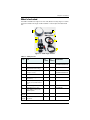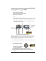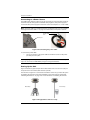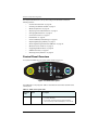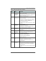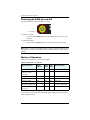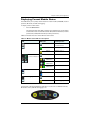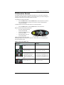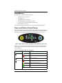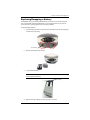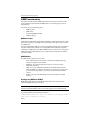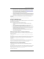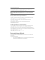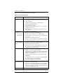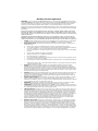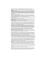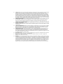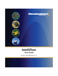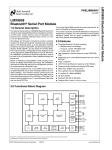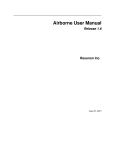
1
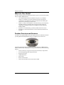
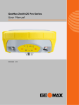
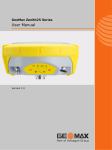
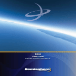
S320
GNSSName
Receiver
Product
GuideGuide
QuickUser
Reference
Part No. 875-0281-000
Part No. Rev A2
Environmental
Temperature – operating -30C to +65C
Temperature – storage -40C to +85C
Humidity MIL-STD-810F Method 5-7.4
Vibration MIL-STD-810F FIG. 514.5C-1
Loose cargo MIL-STD-810F FIG. 514.5C-5
Regulatory Compliance
CE Compliance
•
EN 301 489-1 v1.8.1
•
EN 301 489-3 v1.4.1
•
EN 301 489-7 v1.3.1
FCC Compliance
•
FCC Part 15 Subpart B
•
FCC Part 22
•
FCC Part 24
IC Compliance
•
RSS210
•
RSS132 Issue 2
•
RSS133 Issue 5
Certifications
•
FCC ID: ZC8S320
•
IC: 9586A-S320
Contains Bluetooth Module:
•
FCC ID: ED9LMX9838
•
IC: 1520A-LMX9838
Contains UHF radio module:
•
If 900MHz
FCC ID: NS908P24IC: 3143A-08P24
•
If 400MHz
FCC ID: NS909P30IC: 3143A-09P30
Before using the 400 MHz radio module you must obtain a valid radio license for
your jurisdiction.
Only set the radio to the frequency and power you are licensed to use at your location.
USA- Federal Communication Commission (FCC)
Radiofrequency radiation exposure Information:
This equipment complies with FCC radiation exposure limits set forth for an uncontrolled
environment.
GSM Mode
•
When using the GSM to receive correction data, this equipment should be installed and
operated with a minimum distance of 20 cm between the radiator and your body.
UHF Radio Mode
•
When using the 900 MHz, n920 from Microhard, this equipment should be installed and
operated with minimum distance of 23 cm.
•
When using the 400 MHz radio, nL400 from Microhard, this equipment should be installed
and operated with a minimum distance of 24 cm.
This transmitter must not be co-located or operating in conjunction with any other antenna or
transmitter.
Modifications not expressly approved by Hemisphere GPS could void the user's authority to
operate the equipment.
This device complies with Part 15 of the FCC Rules. Operation is subject to the following two
conditions: (1) this device may not cause harmful interference, and (2) this device must accept any
interference received, including interference that may cause undesired operation.
This equipment has been tested and found to comply with the limits for a Class B digital device,
pursuant to Part 15 of FCC Rules. These limits are designed to provide reasonable protection
against harmful interference in a residential installation.
This equipment generates, uses, and can radiate radio frequency energy. If not installed and used
in accordance with the instructions, it may cause harmful interference to radio communications.
However, there is no guarantee that interference will not occur in a particular installation.
If this equipment does cause harmful interference to radio or television reception, which can be
determined by tuning the equipment off and on, the user is encouraged to try and correct the
interference by one or more of the following measures:
•
Reorient or relocate the receiving antenna.
•
Increase the distance between the equipment and the receiver.
•
Connect the equipment to outlet on a circuit different from that to which the receiver is
connected.
•
Consult the dealer or an experienced radio/TV technician for help.
Any changes or modifications not expressly approved by the party responsible for compliance
could void the user's authority to operate the equipment.
Caution: Exposure to Radio Frequency Radiation.
This device must not be co-located or operating in conjunction with any other antenna or
transmitter.
Canada - Industry Canada (IC)
This device complies with RSS 210 of Industry Canada. Operation is subject to the following two
conditions: (1) this device may not cause interference, and (2) this device must accept any
interference, including interference that may cause undesired operation of this device.
L ' utilisation de ce dispositif est autorisée seulement aux conditions suivantes: (1) il ne doit pas
produire d'interference et (2) l' utilisateur du dispositif doit étre prêt à accepter toute interference
radioélectrique reçu, même si celle-ci est susceptible de compromettre le fonctionnement du
dispositif.
Caution: Exposure to Radio Frequency Radiation.
The installer of this radio equipment must ensure that the antenna is located or pointed such that it
does not emit RF field in excess of Health Canada limits for the general population; consult Safety
Code 6, obtainable from Health Canada's website http://www.hc-sc.gc.ca/rpb.
Europe – Declaration of Conformity
This device is in compliance with the essential requirements of the R&TTE Directive 1999/5/EC.
Copyright Notice
Hemisphere GPS Precision GPS Applications
Copyright © Hemisphere GPS (2011). All rights reserved.
No part of this manual may be reproduced, transmitted, transcribed, stored in a retrieval system or
translated into any language or computer language, in any form or by any means, electronic,
mechanical, magnetic, optical, chemical, manual or otherwise, without the prior written
permission of Hemisphere GPS.
Trademarks
Hemisphere GPS®, the Hemisphere GPS logo, A100TM, A20TM, A21TM, A220TM, A221TM, A30TM,
A31TM, A42TM, A52TM, AerialACETM, AirStarTM, AirTracTM, AutoMateTM, BantamTM, BaseLineHDTM,
BaseLineXTM, BEELINE®, COASTTM, Contour LockTM, Crescent®, Earthworks®, EclipseTM, e-Dif®,
eDrive®, eDriveTCTM, eDriveVSiTM, eDriveXTM, FliteTracTM, G100TM, GateMateTM, GPSteerTM, H102TM,
HQTM, IntelliFlow®, IntelliGateTM, IntelliStarTM, IntelliTracTM, Just Let GoTM, L-DifTM, LiteStar IITM,
LV101TM, LX-1TM, LX-2TM, M3TM, MapStar®, MBX-4TM, miniEclipseTM, OutbackTM, Outback 360TM,
Outback Guidance CenterTM, Outback Guidance®, Outback HitchTM, Outback STM, Outback S2TM,
Outback S3TM, Outback S-LiteTM, Outback StsTM, Outback Steering GuideTM, PocketMAX PCTM,
PocketMAXTM, PocketMax3TM, R100TM, R131TM, R220TM, R320TM, Satloc®, the Satloc logo, SBX-4TM,
V101TM, V102TM, V111TM, VS101TM, VS111TM, VectorTM, X200TM, X300TM, XF100TM, XF101TM, and
XF102TM are proprietary trademarks of Hemisphere GPS. Other trademarks are the properties of
their respective owners.
Patents
The Outback STM and S-LiteTM automated navigation and steering guide systems are covered by
U.S. Patents No. 6,539,303 and No. 6,711,501. The Outback HitchTM automated hitch control system
is covered by U.S. Patent No. 6,631,916. The Outback eDriveTCTM GPS assisted steering system is
covered by U.S. Patent No. 7,142,956. Hemisphere GPS products may be covered by one or more
of the following U.S. Patents:
6,111,549
6,397,147
6,469,663
6,501,346
6,539,303
6,549,091
6,631,916
6,711,501
6,744,404
6,865,465
6,876,920
7,142,956
7,162,348
7,277,792
7,292,185
7,292,186
7,373,231
7,400,956
7,400,294
7,388,539
7,429,952
7,437,230
7,460,942
Other U.S. and foreign patents pending.
Notice to Customers
Contact your local dealer for technical assistance. To find the authorized dealer near you:
Hemisphere GPS
4110 9th Street S.E.
Calgary, Alberta, Canada T2G 3C4
Phone: 403-259-3311
Fax: 403-259-8866
[email protected]
www.hemispheregps.com
Technical Support
If you need to contact Hemisphere GPS Technical Support:
8444 N 90th St, Suite 130
Scottsdale, AZ 85258 USA
Phone: (480) 348-9919
Fax: (480) 348-6370
[email protected]
Documentation Feedback
Hemisphere GPS is committed to the quality and continuous improvement of our products and
services. We urge you to provide Hemisphere GPS with any feedback regarding this guide by
writing to the following email address: [email protected].
Contents
Chapter 1
Introduction . . . . . . . . . . . . . . . . . . . . . . . . . . . . . . 1
What’s In This Guide? . . . . . . . . . . . . . . . . . . . . . . . . . . . . . . . . . . . . 2
Product Overview and Features . . . . . . . . . . . . . . . . . . . . . . . . . . . . 2
What’s Included . . . . . . . . . . . . . . . . . . . . . . . . . . . . . . . . . . . . . . . . . 3
Chapter 2
Installation . . . . . . . . . . . . . . . . . . . . . . . . . . . . . . . 5
Ports and Connections . . . . . . . . . . . . . . . . . . . . . . . . . . . . . . . . . . . . 6
Installing/Connecting the S320 . . . . . . . . . . . . . . . . . . . . . . . . . . . . . 7
Attaching the Antenna . . . . . . . . . . . . . . . . . . . . . . . . . . . . . . . . 7
Connecting to a Power Source . . . . . . . . . . . . . . . . . . . . . . . . . 8
Setting Up the Unit . . . . . . . . . . . . . . . . . . . . . . . . . . . . . . . . . . 8
Chapter 3
Setup and Configuration . . . . . . . . . . . . . . . . . . . . 9
Control Panel Overview . . . . . . . . . . . . . . . . . . . . . . . . . . . . . . . . . . 10
Powering the S320 On and Off . . . . . . . . . . . . . . . . . . . . . . . . . . . . 12
Modes of Operation . . . . . . . . . . . . . . . . . . . . . . . . . . . . . . . . . . . . . 12
Displaying Current Module Status . . . . . . . . . . . . . . . . . . . . . . . . . 13
Changing Module Status . . . . . . . . . . . . . . . . . . . . . . . . . . . . . . . . . 14
Tilt Function Control . . . . . . . . . . . . . . . . . . . . . . . . . . . . . . . . . . . . 15
Alarm/Buzzer . . . . . . . . . . . . . . . . . . . . . . . . . . . . . . . . . . . . . . . . . . 16
Power and Battery Status/Charge . . . . . . . . . . . . . . . . . . . . . . . . . . 16
Replacing/Swapping a Battery . . . . . . . . . . . . . . . . . . . . . . . . . . . . 17
Removing/Inserting the SD Card / SIM Card . . . . . . . . . . . . . . . . . 18
Bluetooth Communication . . . . . . . . . . . . . . . . . . . . . . . . . . . . . . . 19
Upgrading S320 Firmware . . . . . . . . . . . . . . . . . . . . . . . . . . . . . . . 20
Upgrading S320 Firmware via Serial Port . . . . . . . . . . . . . . . 20
Upgrading S320 Firmware via SD Card . . . . . . . . . . . . . . . . . 21
GSM Functionality . . . . . . . . . . . . . . . . . . . . . . . . . . . . . . . . . . . . . . 22
GSM Overview . . . . . . . . . . . . . . . . . . . . . . . . . . . . . . . . . . . . . 22
GSM Modes . . . . . . . . . . . . . . . . . . . . . . . . . . . . . . . . . . . . . . . 22
Configuring GSM for NTRIP . . . . . . . . . . . . . . . . . . . . . . . . . . 22
Configuring SMS Messaging . . . . . . . . . . . . . . . . . . . . . . . . . 23
Restoring Factory Defaults . . . . . . . . . . . . . . . . . . . . . . . . . . . . . . . 24
Appendix A
Troubleshooting . . . . . . . . . . . . . . . . . . . . . . . . . . 25
Appendix B
Technical Specifications . . . . . . . . . . . . . . . . . . . 27
Index . . . . . . . . . . . . . . . . . . . . . . . . . . . . . . . . . . . . . . . . . . . . . . . 31
End User License Agreement . . . . . . . . . . . . . . . . . . . . . . . . . . . . 33
Warranty Notice . . . . . . . . . . . . . . . . . . . . . . . . . . . . . . . . . . . . . . 36
S320 User Guide
v
PN 875-0281-000 Rev A2
Chapter 1: Introduction
What’s In This Guide?
Product Overview and Features
What’s Included
S320 User Guide
1
PN 875-0281-000 Rev A2
Chapter 1: Introduction
What’s In This Guide?
This User Guide provides the following information to get you up and running quickly
with your S320™ GNSS Receiver:
•
This chapter briefly describes the S320 and the parts in your S320 kit.
•
Chapter 2, “Installation” provides a detailed overview of the physical
specifications of the S320 and includes such information as attaching the
antenna and connecting to a power source.
•
Chapter 3, “Setup and Configuration” describes setting up and configuring
the S320, performing such basic tasks as using the control panel and
swapping and charging the batteries, and GSM functionality regarding
NTRIP and SMS.
•
Appendix A, “Troubleshooting” provides possible solutions for issues.
•
Appendix B, “Technical Specifications” lists the technical specifications of
the S320.
Product Overview and Features
The S320 is an integrated GNSS survey and mapping device for mobile data collection
providing differential GPS (DGPS) accuracy in a rugged, all-in-one enclosure.
Powered by Hemisphere GPS’ powerful dual-frequency Eclipse™ II OEM board, the
S320 is suitable for GIS, mapping, land surveying, and construction with the following
features:
•
Can be mounted on a range pole or tripod and carried by a single worker
•
Small and lightweight with good pole balance
•
Rugged construction
•
Integrated batteries
•
Data storage
•
Radio communications
•
Fully functional without the need for external cables
S320 User Guide
2
PN 875-0281-000 Rev A2
Chapter 1: Introduction
What’s Included
The S320 is available as a single unit or two units (base/rover setup). Figure 1-1 shows
the parts included in the single unit kit and Table 1-1 lists the parts included in both
kits.
A
B
C
D
F
E
H
G
Figure 1-1: S320 single unit kit
Table 1-1: S320 parts list
Item
Item
Qty
(1 Unit)
Qty
(2 Units)
Part Number
A
S320
1
2
804-0079-000 (400 MHz)
804-0090-000 (900 MHz)
B
Antenna bracket (for upward
vertical antenna mounting)
1
2
C
Antenna (model/type depends
on region of use)
1
2
D
SD card
1
2
750-1099-000
E
Batteries (rechargeable
lithium-ion)
2
4
427-0043-000
F
Power cable, external, 2-pin
circular, 3 m (for base station
unit)
N/A
1
054-0119-000
G
Battery charger
1
2
427-0044-000
H
Data cable, 9-pin to 9-pin
serial, USB connector, and
USB receptacle
1
2
051-0258-000
Not
shown
Pelican case
1
1
002-0083-000
Not
shown
S320 User Guide (this
document)
1
1
875-0281-000
S320 User Guide
602-1096-000
150-0021-000 (400 MHz)
150-0022-000 (900 MHz)
3
PN 875-0281-000 Rev A2
Chapter 2: Installation
Ports and Connections
Installing/Connecting the S320
S320 User Guide
5
PN 875-0281-000 Rev A2
Chapter 2: Installation
Ports and Connections
All connections and ports are located on the bottom of the unit, as shown in
Figure 2-1. Table 2-1 provides additional information about each port/connection.
Data port
Power port
Antenna port
Pole mount
Serial port
Figure 2-1: S320 ports and connectors
Table 2-1: S320 ports and connections
Port
What to connect
Antenna port
External antenna (Item C in Table 1-1 on page 3)
Serial port
External serial devices
Data port
Data cable (Item H in Table 1-1 on page 3)
Power port
External power cable (Item F in Table 1-1 on page 3)
Mounting hole
Pole or tripod mount
S320 User Guide
6
PN 875-0281-000 Rev A2
Chapter 2: Installation
Installing/Connecting the S320
This section describes how to perform the following:
•
Attaching the antenna (see below)
•
Connecting to a power source (see page 8)
•
Setting up the unit (see page 8)
Attaching the Antenna
You can attach the antenna in one of two ways:
•
Attaching the antenna directly to the antenna port on the bottom of the unit
with the antenna vertical and pointing downward (left photo in Figure 2-2)
•
Attaching the antenna bracket to the unit and then attaching the antenna to
the port at the end of the bracket with the antenna vertical and pointing
upward (right photo in Figure 2-2)
Bracket attached
to unit and anten
inserted into
bracket
Antenna inserted
directly into unit
Antenna bracket
Figure 2-2: Antenna installation options
Tip: The antenna bracket offers an alternative solution in situations where installing
the antenna on the bottom of the unit may not provide suitable reception, such as
where a small increase in antenna height has a noticeable effect on reception.
To install the antenna directly into the unit:
1.
On the bottom of the unit remove the rubber cap covering the antenna port.
2.
Screw the antenna into the antenna port until snug. Do not overtighten.
To install the antenna using the antenna bracket:
1.
Align the bracket to fit into the
recessed area on the bottom of
the unit (as shown at right).
2.
Using the two thumbscrews on
the bracket secure the bracket to
the unit. Do not overtighten.
Antenna port
3.
Attach the bracket’s antenna cable to the unit’s antenna port.
4.
Screw the antenna into the bracket’s antenna port until snug. Do not
overtighten.
S320 User Guide
7
PN 875-0281-000 Rev A2
Chapter 2: Installation
Connecting to a Power Source
The S320 power cable has a two-pin circular connector at one end and two clamps at
the other end (red clamp positive and black clamp negative). The power supply is a
nominal 12 VDC power supply and maximum current consumption is < 1 A at 12 VDC.
Note: The power cable is included with the two-unit base/rover kit; it is not included in
the single-unit kit. See Table 1-1 on page 3 for information on the parts in each kit.
Power cable
end
Power port
Figure 2-3: Connecting the power cable
To connect the power cable:
•
Line up the red dot on the power cable end with the red dot on the power
port and press into place.
Note: Applying external power does not charge the Li-ion batteries in the battery
trays. You must use a suitable battery charger to charge the batteries.
Setting Up the Unit
Figure 2-4 shows a typical setup for both a base station unit and a rover unit (tripod
and pole mount not included, data collector optional).
The antenna in Figure 2-4 is connected to the bottom of the unit; you have the option
of attaching the antenna to the antenna bracket so the antenna faces upward. See
“Attaching the Antenna” on page 7 for more information on attaching the antenna.
Base setup
Rover setup
Figure 2-4: Typical base and rover setup
S320 User Guide
8
PN 875-0281-000 Rev A2
Chapter 3: Setup and Configuration
Control Panel Overview
Powering the S320 On and Off
Modes of Operation
Displaying Current Module Status
Changing Module Status
Tilt Function Control
Alarm/Buzzer
Power and Battery Status/Charge
Replacing/Swapping a Battery
Removing/Inserting the SD Card / SIM Card
Bluetooth Communication
Upgrading S320 Firmware
GSM Functionality
Restoring Factory Defaults
S320 User Guide
9
PN 875-0281-000 Rev A2
Chapter 3: Setup and Configuration
This chapter describes how to set up and configure the S320 and includes the
following sections:
•
“Control Panel Overview” on page 10
•
“Powering the S320 On and Off” on page 12
•
“Modes of Operation” on page 12
•
“Displaying Current Module Status” on page 13
•
“Changing Module Status” on page 14
•
“Tilt Function Control” on page 15
•
“Alarm/Buzzer” on page 16
•
“Power and Battery Status/Charge” on page 16
•
“Replacing/Swapping a Battery” on page 17
•
“Removing/Inserting the SD Card / SIM Card” on page 18
•
“Bluetooth Communication” on page 19
•
“Upgrading S320 Firmware” on page 20
•
“GSM Functionality” on page 22
•
“Restoring Factory Defaults” on page 24
Control Panel Overview
You operate the S320 using the control panel shown in Figure 3-1.
4
1
2
3
5
7
8
6
A
B
Figure 3-1: S320 control panel
The S320 beeps on any keypress. Table 3-1 describes the each button and LED of the
control panel.
Table 3-1: S320 control panel items
Diagram
Item
Name
Description
A
Power button
•
If unit is Off, press and hold until unit powers up (until
you hear one beep)
•
If unit is On, press and hold for approximately 3
seconds (until you hear three beeps) to turn unit off
S320 User Guide
10
PN 875-0281-000 Rev A2
Chapter 3: Setup and Configuration
Table 3-1: S320 control panel items (continued)
Diagram
Item
B
1
2
3
4
5 and 6
7
8
Name
Description
Select button
(for Bluetooth/
UHF/GSM/SD
modules)
Allows you to review module status or change the status
(power on/off) of a module
UHF/GSM radio
status LED
•
GPS position
status LED
See “Displaying Current Module Status” on page 13 and
“Changing Module Status” on page 14 for more
information on the Select button.
Off – UHF radio or GSM module is OFF; or no RTK
position computed
•
On (yellow) – floating point RTK position achieved
•
On (green) – fixed ambiguity RTK position achieved
•
Blink (green) – UHF radio or GSM module
transmitting/receiving data
•
Pulse (red) – error condition with UHF radio or GSM
module
•
Off – no position
•
On (yellow) – valid position
•
Blink (yellow) – operating as a base station and
converging on reference coordinates
DGPS position
status LED
•
Off – no differential corrections available
•
On (green) – differentially corrected position
computed
External power
status LED
•
Off – external power not present
•
On (red) – external power present and in use
Battery status
LED
•
Off – battery not present
Bluetooth status
LED
SD logging
status LED
S320 User Guide
•
On (green) – battery charge full
•
On (yellow) – battery charge < 50%
•
On (red) – battery charge depleted
•
Blink – battery in use
•
Off – Bluetooth inactive
•
On (blue) – active Bluetooth connection
•
Blink (blue) - Bluetooth active and transmitting/
receiving data
•
Off – SD card not inserted
•
On (yellow) – SD card inserted, not logging data
•
Blink (yellow) - SD card inserted and reading/writing
data to SD card
•
Pulse (yellow) at 5 Hz - SD card inserted and low free
space
11
PN 875-0281-000 Rev A2
Chapter 3: Setup and Configuration
Powering the S320 On and Off
Use the Power button to power the S320 on and off.
Power button
To power on the S320:
•
Press and hold the Power button until the S320 powers up (until you hear
one beep)
To power off the S320:
•
Press and hold the Power button for 3 seconds (until you hear 3 beeps)
Note: When you power on the S320 the LEDs go through a ‘heartbeat’ sequence (each
LED lights up in succession); during this time the modules power up and the devices
initialize.
Modes of Operation
Table 3-2 lists the modes of operation for the S320.
Table 3-2: S320 modes of operation
Mode Description
Eclipse
Software
GSM
Mode
UHF
Mode
Bluetooth Mode
OmniSTAR® rover
SBASRTKB
OFF
OFF
ON or OFF
Single point data
collection for post
processing
SBASRTKB
OFF
OFF
ON or OFF
RTK Base Station
SBASRTKB
OFF
ON
ON or OFF
RTK Rover - UHF
RTK
OFF
ON
ON or OFF
RTK Rover - GSM
RTK
ON
OFF
ON or OFF
RTK Rover - External
corrections via Bluetooth
RTK
OFF
OFF
ON (both ports - one
monitor, one diff input)
RTK Rover - External serial
corrections
RTK
OFF
OFF
ON or OFF
You can quickly review and/or change the GSM, UHF, and Bluetooth states using the
Power and Select buttons.
S320 User Guide
12
PN 875-0281-000 Rev A2
Chapter 3: Setup and Configuration
Displaying Current Module Status
The S320 allows you to quickly review the status of each module (UHF/GSM, mode of
operation, Bluetooth, and SD card logging).
To display current module status:
•
Press the Select button
The external power status LED is red (the unit is displaying its current status)
and the LED of each module will be either OFF (LED not illuminated, module
powered off) or ON (LED illuminated, module powered on).
Table 3-3 illustrates the colors of the LEDs for each module.
Table 3-3: Module status LED color descriptions
LED
LED Color
UHF/GSM
GPS and DGPS
position indicators
Bluetooth
SD card logging
S320 Operation
Off
UHF radio and GSM
module both off
Green
UHF radio on
Yellow
GSM module on
Off (both)
OmniSTAR
GPS Yellow
DGPS None
RTK rover
GPS None
DGPS Green
RTK base
GPS Yellow
DGPS Green
e-Dif
Off
Bluetooth off
Blue
Bluetooth on
Off
SD card logging off
Yellow
SD card logging on
For example, in the figure below the UHF radio is on, the unit is in RTK Rover mode,
Bluetooth is active, and SD card logging is on.
S320 User Guide
13
PN 875-0281-000 Rev A2
Chapter 3: Setup and Configuration
Changing Module Status
You change module status by using the Select button to select the module and the
Power button to change the module status.
To change module status:
1.
Press the Select button to display the status of all modules (if the LED is on,
the module is on; if the LED is off, the module is off).
2.
Press the Select button again to select the first module (UHF/GSM).
Note: When you press the Select button the LED (for the module status you
are changing) remains illuminated for 5 seconds, during which time you can use
the Power button to change the module status in step 3.
3.
If you want to change the current module’s status, press the Power button.
Note: When you press the Power button the LED (for the module status you
are changing) blinks 5 times to indicate a status change.
4.
Repeat steps 2 and 3 for each remaining module (if desired).
After a status change, the function of the LEDs return to normal mode.
S320 User Guide
14
PN 875-0281-000 Rev A2
Chapter 3: Setup and Configuration
Tilt Function Control
The S320 includes tilt control functionality that allows you to level your unit based
using five of the LED indicators. When you activate tilt control you see the changes to
the angle of the antenna in real time (similar to a level).
To activate tilt control functionality:
•
Press the Power button and the Select button at the same time. The tilt of
the unit is displayed for a period of 1 minute or until you deactivate tilt
control functionality
To deactivate tilt control functionality (return to normal operation):
•
Press the Power button and the Select button at the same time.
When tilt control functionality is activated:
•
X-axis tilt is displayed along
three horizontal LEDs
•
Y-axis tilt is displayed along
three vertical LEDs
•
Each LED shows a 0.5° tilt
(user-configurable)
X-axis tilt LEDs
Y-axis tilt LEDs
Table 3-4 illustrates the colors of the
LEDs depending on the tilt direction of the unit. These LED colors only apply if you
have activated tilt control.
Table 3-4: Tilt control LED colors
LED Colors
S320 User Guide
Meaning
Middle (right battery) LED is
green
Unit is level
Left LED is green
Unit is off level to the left
Right LED is green
Unit is off level to the right
Left LED is green and middle
(right battery) LED is red
Unit is off level to the left by more
than twice the configurable amount
Right LED is green and
middle (right battery) LED is
red
Unit is off level to the right by more
than twice the configurable amount
Top LED is red
Unit is tilted backward
Bottom LED is red
Unit is tilted forward
15
PN 875-0281-000 Rev A2
Chapter 3: Setup and Configuration
Alarm/Buzzer
The S320 beeps under the following conditions:
•
Whenever you press a button
•
Position is lost
•
Differential position is achieved
•
Bluetooth device is connected/disconnected
•
Low memory for data storage (SD card almost full)
•
Both batteries are very low
If an alarm is sounding, you can silence the alarm by pressing the Power button.
Power and Battery Status/Charge
LEDs on the console provide power and battery status/charge information based on
the color of the LEDs. For example, Figure 3-2 indicates there is no external power, the
right battery is fully charged, and the left battery is not present (not in the unit).
Figure 3-2: No external power, right battery full, left battery not present
Table 3-5 describes what the power/battery LED colors indicate. The S320 prioritizes
power usage to use external power when available, regardless of the status of the
internal batteries.
Table 3-5: Power/battery LED color descriptions
LED
LED Color
Power
Left battery
Right battery
Meaning
Off
No external power
Red
External power present and in use
Off
Battery not present
Red
Battery very low or fully discharged (unit will
beep when both batteries are very low)
Yellow
Battery less than 1/2 charged
Green
Battery fully charged
Note: A blinking battery light indicates that battery is in use.
S320 User Guide
16
PN 875-0281-000 Rev A2
Chapter 3: Setup and Configuration
Replacing/Swapping a Battery
If the S320 is off you can replace both batteries at one time. If you want to keep the
unit running while replacing the batteries you must replace them one at a time to
ensure the unit is receiving power from at least one battery.
To replace/swap a battery:
1.
For the battery you want to replace remove the battery tray by squeezing the
thumb lever and pulling.
Thumb lever
2.
Remove the battery from the tray.
3.
Insert the new battery.
Note: When inserting the battery make sure the end with the leads (on top)
points away from the tray.
Battery leads
4.
Replace the tray, making sure the tray snaps into place.
S320 User Guide
17
PN 875-0281-000 Rev A2
Chapter 3: Setup and Configuration
Removing/Inserting the SD Card / SIM Card
Caution: Use electrostatic discharge (ESD) protection, such as by wearing an
ESD strap that is attached to an earth ground, before inserting or removing
the SIM card on the S320. If an ESD strap is not available then touch a metal
object prior to accessing the SIM card holder.
The SD card and the SIM card are only accessible by first removing the appropriate
battery tray, where the:
•
Left tray is labeled “SD”
•
Right tray is labeled “SIM”
To remove the SD card or SIM card:
1.
Remove the left battery tray.
2.
Place the S320 upside down (on its top) to get a better view of the card.
notch end
goes n first
notch end
goes in first
SIM
card
3.
SD
card
Gently push the card in; it will then snap back and slightly out.
Note: When you insert either card make sure the contacts on the card are
facing the top of the unit and the side of the card with the notch goes in first
(see figure in step 2 above).
4.
Remove the card.
To insert the SD card or SIM card:
1.
Place the card in its appropriate card slot.
2.
Gently push the card in until it clicks.
3.
Replace the battery tray.
S320 User Guide
18
PN 875-0281-000 Rev A2
Chapter 3: Setup and Configuration
Bluetooth Communication
If you have a Bluetooth-enabled device, such as a data collector, you can wirelessly
communicate with the S320.
When you attempt to connect the S320 to a Bluetooth-enabled device, such as a
handheld data collector, the following S320 Bluetooth information appears on the
device:
HGPS S320 XXXXXX
where “XXXXXX” is the Eclipse board serial number
To complete the connection you must use the correct PIN/Passkey, which is 0000.
Table 3-6 describes the Bluetooth status LED options.
Table 3-6: Bluetooth LED status
LED Colors
Meaning
Off
Bluetooth inactive
Blue
Active Bluetooth connection
Blue blinking/pulsing
S320 User Guide
Active Bluetooth connection and
transmitting/receiving data
19
PN 875-0281-000 Rev A2
Chapter 3: Setup and Configuration
Upgrading S320 Firmware
You can upgrade S320 firmware via serial port or SD card.
Upgrading S320 Firmware via Serial Port
Before you upgrade verify the S320 is powered off and, if you will not be using
external power, both Li-ion batteries are fully charged and inserted into the S320.
1.
Download the Autoloader_S320 executable (.exe file) for the most recent
version from the Hemisphere GPS website at www.hemispheregps.com and
save it to your PC.
2.
Using the data cable included in your S320 kit, connect the DB9 serial port
end of the cable to your PC and connect the other end of the cable to the
data port on the S320 (see below):
To S320 data port
To PC serial port
Not used in this
procedure
3.
Power on the S320.
4.
Double-click the Autoloader_S320 file you download in step 1 to start the
Autoloader program.
5.
In the Com Port drop-down box select the appropriate COM port on your PC
and then click Load.
Status area
shows the
load progress
S320 User Guide
20
PN 875-0281-000 Rev A2
Chapter 3: Setup and Configuration
The Status area shows the load progress. When loading is complete the
following message appears.
6.
Click OK.
7.
In the Autoloader window click Exit.
Upgrading S320 Firmware via SD Card
Before you upgrade verify the S320 is powered off and, if you will not be using
external power, both Li-ion batteries are fully charged and inserted into the S320.
1.
Download the S320_Upgrade.zip file from the Hemisphere GPS website at
www.hemispheregps.com and save it to your PC.
2.
Unzip the file and extract the contents to the root folder of the SD card,
ensuring the same folder structure of the contents on the SD card.
3.
Remove the SD card from the PC.
4.
If necessary remove the left battery tray from the S320 (the left tray is
labeled SD).
5.
Insert the SD card into the S320 (see “Removing/Inserting the SD Card / SIM
Card” on page 18).
6.
Replace the battery tray.
7.
Power on the S320.
a.
The LEDs cycle from left to right while the receiver is reading the
upgrade file.
b.
After the file has passed all internal verifications, the bottom battery
LED illuminates green.
c.
The LEDs cycle from left to right while the file is copied.
d.
All the LEDs flash quickly to indicate the new firmware file is being
committed to the receiver.
e.
After committing the new file to internal flash, the LEDs cycle from left
to right one more time before resetting the receiver and returning to the
heartbeat sequence.
The upgrade is complete.
S320 User Guide
21
PN 875-0281-000 Rev A2
Chapter 3: Setup and Configuration
GSM Functionality
This section provides advanced GSM information that requires connection to a PC
running either Hemisphere GPS’ PocketMax utility or a terminal program such as
HyperTerminal.
This section covers the following topics:
•
GSM overview
•
GSM modes
•
Configuring GSM for NTRIP
•
SMS messaging
GSM Overview
Global System for Mobile Communications (GSM) is a network technology for mobile
phone communications. The GSM modem in the S320 is what allows you to connect
to a GSM carrier.
The Access Point Name (APN) is a protocol that allows the S320 to access the internet
using the mobile phone network. It is a configurable network identifier used when
connecting to a GSM carrier. The default APNCFG value is "internet.com". The specific
APN required by the S320 depends on your mobile carrier. Check with your mobile
provider for details.
GSM Modes
The GSM module operates in four modes:
•
IDLE - Default mode for the module. In this state, the GSM module only
attempts to register on the network.
•
DIRECT IP - For users who have direct access to a server providing
differential corrections.
•
LINK - For users to establish a link between two S320 modules directly,
where the BASE has a dynamic IP address. You should only use this mode
on the rover in a base station / rover setup (use IDLE mode for the base
station).
•
NTRIP - Used to provide differential correction information to the GPS
receiver.
Configuring GSM for NTRIP
NTRIP (Networked Transport of RTCM via Internet Protocol) is the protocol for
transmitting GNSS data over the internet.
Note: To configure NTRIP you must connect the S320 to a PC running either
Hemisphere GPS’ PocketMax utility or a terminal program such as HyperTerminal.
To configure NTRIP send the following command:
$GSMCFG,NTRIP,[remote host name or IP address],[port number],[mount
point name],[[username],[password]]
where,
S320 User Guide
22
PN 875-0281-000 Rev A2
Chapter 3: Setup and Configuration
•
Remote host name - server name (such as www.igs-ip.net) or an IP address
•
Mount point name - caster stream name from NTRIP Caster Source Table
(you can download a sample source table from http://www.igs-ip.net:2101/).
If you leave this field blank, the S320 will fetch the caster source table and
select the mount point closest to its current position.
•
User name and password - authentication with a user name and password is
required for most NTRIP casters. You can leave both blank to specify that no
authentication is required. The user name and password are case sensitive.
For example, to connect to the CALG0 stream on igs-ip.net send the following
command:
$GSMCFG,NRTIP,www.igs-ip.net,2101,CALG0,Usrnam,passwd
Configuring SMS Messaging
The S320 supports Short Message Service (SMS) configuration and event updates for
both base and rover operations.
When using SMS messaging keep the following in mind:
•
The GSM module must be powered on for SMS commands to work
correctly.
•
You can send SMS messages to the S320 from up to three numbers and
these numbers must be added to S320 approved numbers list.
•
By default the approved numbers list is comprised of the first three entries in
the SIM card address book. However, for a typical data-only SIM card, the
address book of the SIM card will be empty.
•
Use the appropriate country code (the following procedures use the “+1”
country code for USA/Canada).
Adding or Overwriting a Number on the Approved Number List
You can add a number to an empty slot or overwrite an existing number using the
following command:
$JSMS,CONFIG,[slot number 1/2/3],[number],[name],[status messages
ON | OFF]
For example, to add “Service” (USA phone number 999-555-1212) to slot 1 with status
messages OFF (or to replace the current number in slot 1) send the following
command:
$JSMS,CONFIG,1,+19995551212,Service,OFF
The status message state (ON or OFF) allows the S320 to send an SMS back to the
number to report information and events on the operation of the unit.
Displaying the Current List of Approved Numbers
To display the current list of approved numbers send the following command:
$JSMS,CONFIG
The reply below contains all information on the configured numbers and may include
SIM card address book defaults that you can overwrite with your own information.
$>JSMS,CONFIG,1,1,+19995551212,Service,OFF
The format of the reply is:
S320 User Guide
23
PN 875-0281-000 Rev A2
Chapter 3: Setup and Configuration
$>JSMS,CONFIG,[number of approved numbers],[slot number 1/2/
3],[number],[name],[status messages ON | OFF]
Note: The reply contains one line for each number. For example, if there are two
approved numbers then the reply will contain a “$>JSMS,CONFIG” line for each
number.
Deleting a Number from the Approved Number List
To delete a number from the approved number list, send the following command:
$JSMS,CONFIG,[1/2/3 or keyword ALL],DELETE
For example, to delete the number in slot 2 send the following command:
$JSMS,CONFIG,2,DELETE
And to delete all numbers from the list, send the following command:
$JSMS,CONFIG,ALL,DELETE
Sending an SMS Message to an Approved Number
To send an SMS message to an approved number, send the following command:
$JSMS,SEND,[name or phone number or slot number],[message]
For example, to send a “This is a test” message to Customer Support (USA phone
number 480-348-9919, slot number 2) you can send either of the following commands:
$JSMS,SEND,SERVICE,This is a test
$JSMS,SEND,+14803489919,This is a test
$JSMS,SEND,2,This is a test
Restoring Factory Defaults
If you need to restore your factory defaults for any reason you can do this via the
Control panel.
To restore factory defaults:
•
Press and hold the Power button for 10 to 20 seconds and release it while
the GPS status and DGPS status LEDs are blinking.
S320 User Guide
24
PN 875-0281-000 Rev A2
Appendix A: Troubleshooting
S320 User Guide
25
PN 875-0281-000 Rev A2
Appendix A: Troubleshooting
Table A-1 provides troubleshooting tips for the S320.
Table A-1: S320 troubleshooting
Issue
Possible Resolution
Receiver fails to
power
•
External power is low
•
Check charge on external battery and the fuse on the power
cable if applicable
•
Internal power: Check charge on internal batteries
•
Check all power cables and pins
•
Try other batteries or cables
•
Make sure to hold the power button down for a minimum of
one full second to turn on
•
Ensure batteries are installed with contacts pointed in the
correct direction
No data logged
•
(1) Check receiver power status
1.
No
communication
•
(2) Verify it is locked to a valid DGPS signal
•
(2) Verify that it is locked to 4 or more GPS satellites
2.
No valid data
•
(2) Check integrity and connectivity of power and data cable
connections
•
Verify that the baud rate settings match
•
If trying to connect over Bluetooth, ensure Bluetooth module
is powered ON and device is paired prior to opening the port
•
Verify that the RCTM or the Bin messages are not being
accidentally output (send a $JSHOW command)
•
Verify that the baud rate settings match
•
Potentially, the volume of data requested to be output could
be higher than the current baud rate supports. Try using a
higher baud rate for communications
•
Verify antenna’s view of the sky, especially toward that SBAS
satellites, south in the northern hemisphere
•
Verify the bit error rate (BER) and lock status of SBAS satellites
(this can often be done on the receiving device or by using
SLXMon - monitor BER value)
•
Verify that the proper application is running on the Eclipse
(SBASRTKB)
•
Set the satellite selection to automatic mode $JFREQ,AUTO
•
Set the differential mode to $JDIFF,WAAS
•
Ensure there is SBAS coverage in your area
•
Verify that the baud rate of the RTCM input port matches the
baud rate of the external source
•
Verify the pinout between the RTCM source and the RTCM
input port (the “ground” pin and pinout must be connected,
and from the “transmit” from the source must connect to the
“receiver” of the RTCM input port)
•
If using RTK, ensure receiver is properly authorized for RTK.
Random binary data
from Eclipse OEM
board
No GNSS position
No DGPS position in
external RTCM mode
Non-DGPS output
S320 User Guide
26
PN 875-0281-000 Rev A2
Appendix B: Technical Specifications
S320 User Guide
27
PN 875-0281-000 Rev A2
Appendix B: Technical Specifications
The following tables provide information on the technical specifications of the S320.
Table B-1: GNSS receiver specifications
Item
Specification
Receiver type
Dual frequency GNSS
Channels
All in view
12 L1CA GPS
12 L1P GPS
12 L2P GPS
12 L2C GPS
12 L1 GLONASS
12 L2 GLONASS
3 SBAS or 3 additional L1CA GPS
1 L-Band (OmniSTAR)
Note: Some options may require a subscription.
Positioning modes
RTK, OmniSTAR (VBS/HP/XP/G2), ROX, SBAS,
External RTCM, Autonomous
RTK formats
CMR, CMR+, RTCM3
OmniSTAR formats
VBS/HP/XP,G2
Update rate / recording interval
Selectable from 1, 2, 4, 5, 10 Hz
(20 Hz available)
Static performance
Horizontal 5 mm + 0.5 ppm
Cold start time
< 60 s typical (no almanac or RTC)
Table B-2: Performance specifications
Item
Specification
Static performance
Horizontal 5 mm + 0.5 ppm
DGPS performance
< 0.3 m
Table B-3: Horizontal accuracy specifications
Item
Description
2DRMS (95%)
10 mm + 1 ppm
20 mm + 2 ppm
1,3
0.1 m
0.2 m
1
0.3 m
0.6 m
1.2 m
2.5 m
RTK1,2
OmniSTAR HP
SBAS (WAAS)
RMS (67%)
Autonomous, no SA1
S320 User Guide
28
PN 875-0281-000 Rev A2
Appendix B: Technical Specifications
Table B-4: Communication and port specifications
Item
Description
Bluetooth
Dual port
Radio GSM options
Integrated
1 x GSM/GPRS
1 x SS (900 MHz or UHF range: 400 MHz)
CDMA capable
Baud rates
4800 - 115200
Serial ports
1 x RS-232 (9-pin circular, multi use)
1 x RS-232 (9-pin DSUB)
Power port
1 x Power input (2-pin circular)
USB
1 USB Host
1 USB Device (9-pin circular)
Table B-5: Environmental specifications
Item
Specification
Operating temperature
-30°C to +65°C (-22°F to +149°F)
Storage temperature
-40°C to +85°C (-40°F to +185°F)
Humidity
Up to 100% condensing
Enclosure
IP67
Shock
EP455, 2 m (6.56 ft) pole drop
Table B-6: Power specifications
Item
Specification
Battery
2 x lithium ion, 2.6 Ah each, 5.2 Ah total, 7.2 V
External voltage
9 to 32 VDC
Table B-7: Mechanical specifications
Item
Description
Dimensions
114 H x 197 D mm
(4.49 H x 7.76 D in)
Weight
1.51 kg (3.33 lb)
Material
Plastic
1
Depends on multipath environment, number of satellites in view, satellite geometry,
and ionospheric activity.
2
Depends also on baseline length.
3
Requires a subscription from OmniSTAR.
S320 User Guide
29
PN 875-0281-000 Rev A2
Index
A
deactivating tilt control 15
deleting SMS number from approved list
24
device name for Bluetooth 19
DGPS position status LED 11
displaying
current module status 13
SMS approved numbers 23
activating tilt control 15
adding SMS number to approved list 23
alarm 16
antenna 3
attaching 7
bracket 3
port 6
attaching the antenna 7
Autoloader 20
E
Eclipse II 2
environmental specifications 29
External power status LED 11
B
base station setup 8
batteries 3
replacing 17
swapping 17
battery charger 3
battery status 16
Battery status LED 11
Bluetooth 19
device name 19
passkey 19
status LED 11
bracket (antenna) 3
buzzer 16
F
features 2
firmware
upgrading 20
G
GNSS receiver specifications 28
GPS position status LED 11
GSM
configuring for NTRIP 22
functionality 22
modes 22
overview 22
C
cables
data 3, 20
power 3, 8
case 3
changing
module status 14
communication
Bluetooth 19
specifications 29
configuring
GSM for NTRIP 22
SMS messaging 23
connecting to a power source 8
connections 6
mounting hole 6
control panel
overview 10
power button 10
Select button 11
H
horizontal accuracy specifications 28
I
inserting SD/SIM card 18
installation overview 7
L
LED
Battery 11
Bluetooth 11
DGPS position 11
External power 11
GPS position 11
SD logging 11
UHF/GSM 11
M
D
mechanical specifications 29
modes
GSM 22
data cable 3, 20
data port 6
S320 User Guide
31
PN 875-0281-000 Rev A2
Index
Select button 11
sending SMS message to approved number 24
serial port 6
upgrading firmware 20
setting up the S320 8
SIM card
inserting 18
removing 18
Single point mode 12
SMS messaging 23
adding a number to approved list 23
deleting number from approved list
24
displaying approved numbers 23
overwriting a number on approved list
23
sending message to approved number 24
status LED
Battery 11
Bluetooth 11
DGPS position 11
External power 11
GPS position 11
SD logging 11
UHF/GSM 11
swapping batteries 17
operation 12
module status
changing 14
displaying 13
mounting hole 6
N
NTRIP 22
O
OmniSTAR rover mode 12
operation modes 12
overview 2
overwriting SMS number on approved list
23
P
parts list 3
passkey 19
pelican case 3
performance specifications 28
port specifications 29
ports 6
antenna 6
data 6
power 6
serial 6
Power button 10
power cable 3, 8
power port 6
power source connection 8
power specifications 29
power status 16
power supply 8
powering the unit on and off 12
product overview 2
T
technical specifications
communication 29
environmental 29
GNSS receiver 28
horizontal accuracy 28
mechanical 29
performance 28
port 29
power 29
tilt control 15
troubleshooting 26
R
removing SD/SIM card 18
replacing batteries 17
rover setup 8
RTK base station mode 12
RTK rover (external corrections via Bluetooth) mode 12
RTK rover (external corrections via serial)
mode 12
RTK rover (GSM) mode 12
RTK rover (UHF) mode 12
U
UHF/GSM status LED 11
upgrading firmware
overview 20
via SD card 21
via serial port 20
W
S
what’s included 3
SD card 3
inserting 18
removing 18
upgrading firmware 21
SD logging status LED 11
S320 User Guide
32
PN 875-0281-000 Rev A2
End User License Agreement
IMPORTANT - This is an agreement (the "Agreement") between you, the end purchaser ("Licensee") and Hemisphere
GPS Inc. ("Hemisphere") which permits Licensee to use the Hemisphere software (the "Software") that accompanies this
Agreement. This Software may be licensed on a standalone basis or may be embedded in a Product. Please read and
ensure that you understand this Agreement before installing or using the Software Update or using a Product.
In this agreement any product that has Software embedded in it at the time of sale to the Licensee shall be referred to as a
"Product". As well, in this Agreement, the use of a Product shall be deemed to be use of the Software which is embedded
in the Product.
BY INSTALLING OR USING THE SOFTWARE UPDATE OR THE PRODUCT, LICENSEE THEREBY AGREES TO BE LEGALLY
BOUND BY THE TERMS OF THIS AGREEMENT. IF YOU DO NOT AGREE TO THESE TERMS, (I) DO NOT INSTALL OR USE
THE SOFTWARE, AND (II) IF YOU ARE INSTALLING AN UPDATE TO THE SOFTWARE, DO NOT INSTALL THE UPDATE AND
PROMPTLY DESTROY IT.
HEMISPHERE PROVIDES LIMITED WARRANTIES IN RELATION TO THE SOFTWARE. AS WELL, THOSE WHO USE THE
EMBEDDED SOFTWARE DO SO AT THEIR OWN RISK. YOU SHOULD UNDERSTAND THE IMPORTANCE OF THESE AND
OTHER LIMITATIONS SET OUT IN THIS AGREEMENT BEFORE INSTALLING OR USING THE SOFTWARE OR THE PRODUCT.
1.
2.
LICENSE. Hemisphere hereby grants to Licensee a non-transferable and non-exclusive license to use the Software
as embedded in a Product and all Updates (collectively the "Software"), solely in binary executable form.
RESTRICTIONS ON USE. Licensee agrees that Licensee and its employees will not directly or indirectly, in any
manner whatsoever:
a.
install or use more copies of the Software than the number of copies that have been licensed;
b.
use or install the Software in connection with any product other than the Product the Software was intended
to be used or installed on as set out in the documentation that accompanies the Software.
c.
copy any of the Software or any written materials for any purpose except as part of Licensee's normal backup
processes;
d.
modify or create derivative works based on the Software;
e.
sub-license, rent, lease, loan or distribute the Software;
f.
permit any third party to use the Software;
g.
use or operate Product for the benefit of any third party in any type of service outsourcing, application service,
provider service or service bureau capacity;
h.
reverse engineer, decompile or disassemble the Software or otherwise reduce it to a human perceivable form;
i.
3.
4.
5.
6.
7.
8.
9.
Assign this Agreement or sell or otherwise transfer the Software to any other party except as part of the sale
or transfer of the whole Product.
UPDATES. At Hemisphere's discretion Hemisphere may make Updates available to Licensee. An update
("Update") means any update to the Software that is made available to Licensee including error corrections,
enhancements and other modifications. Licensee may access, download and install Updates during the Warranty
Period only. All Updates that Licensee downloads, installs or uses shall be deemed to be Software and subject to this
Agreement. Hemisphere reserves the right to modify the Product without any obligation to notify, supply or install
any improvements or alterations to existing Software.
SUPPORT. Hemisphere may make available directly or through its authorized dealers telephone and email support
for the Software. Contact Hemisphere to find the authorized dealer near you. As well, Hemisphere may make
available user and technical documentation regarding the Software. Hemisphere reserves the right to reduce and
limit access to such support at any time.
BACKUPS AND RECOVERY. Licensee shall back-up all data used, created or stored by the Software on a regular
basis as necessary to enable proper recovery of the data and related systems and processes in the event of a
malfunction in the Software or any loss or corruption of data caused by the Software. Licensee shall assume all risks
of loss or damage for any failure to comply with the foregoing.
OWNERSHIP. Hemisphere and its suppliers own all rights, title and interest in and to the Software and related
materials, including all intellectual property rights. The Software is licensed to Licensee, not sold.
TRADEMARKS. "Hemisphere GPS", "Outback Guidance", "BEELINE", "Crescent", "Eclipse" and the associated logos
are trademarks of Hemisphere. Other trademarks are the property of their respective owners. Licensee may not use
any of these trademarks without the consent of their respective owners.
LIMITED WARRANTY. Hemisphere warrants solely to the Licensee, subject to the exclusions and procedures set
forth herein below, that for a period of one (1) year from the original date of purchase of the Product in which it is
embedded (the "Warranty Period"), the Software, under normal use and maintenance, will conform in all material
respects to the documentation provided with the Software and any media will be free of defects in materials and
workmanship. For any Update, Hemisphere warrants, for 90 days from performance or delivery, or for the balance of
the original Warranty Period, whichever is greater, that the Update, under normal use and maintenance, will
conform in all material respects to the documentation provided with the Update and any media will be free of
defects in materials and workmanship. Notwithstanding the foregoing, Hemisphere does not warrant that the
Software will meet Licensee's requirements or that its operation will be error free.
WARRANTY EXCLUSIONS. The warranty set forth in Section (8) will not apply to any deficiencies caused by (a)
the Product not being used as described in the documentation supplied to Licensee, (b) the Software having been
altered, modified or converted in any way by anyone other than Hemisphere approved by Hemisphere, (c) any
malfunction of Licensee's equipment or other software, or (d) damage occurring in transit or due to any accident,
abuse, misuse, improper installation, lightning (or other electrical discharge) or neglect other than that caused by
Hemisphere. Hemisphere GPS does not warrant or guarantee the precision or accuracy of positions obtained when
using the Software (whether standalone or embedded in a Product). The Product and the Software is not intended
and should not be used as the primary means of navigation or for use in safety of life applications. The potential
10.
11.
12.
13.
14.
15.
16.
17.
18.
19.
20.
positioning and navigation accuracy obtainable with the Software as stated in the Product or Software
documentation serves to provide only an estimate of achievable accuracy based on specifications provided by the
US Department of Defense for GPS positioning and DGPS service provider performance specifications, where
applicable.
WARRANTY DISCLAIMER. EXCEPT AS EXPRESSLY SET OUT IN THIS AGREEMENT, HEMISPHERE MAKES NO
REPRESENTATION, WARRANTY OR CONDITION OF ANY KIND TO LICENSEE, WHETHER VERBAL OR WRITTEN
AND HEREBY DISCLAIMS ALL REPRESENTATIONS, WARRANTIES AND CONDITIONS OF ANY KIND INCLUDING
FITNESS FOR A PARTICULAR PURPOSE, MERCHANTABILITY, ACCURACY, RELIABILITY OR THAT THE USE OF THE
SOFTWARE WILL BE UNINTERRUPTED OR ERROR-FREE AND HEREBY DISCLAIMS ALL REPRESENTATIONS,
WARRANTIES AND CONDITIONS ARISING AS A RESULT OF CUSTOM, USAGE OR TRADE AND THOSE ARISING
UNDER STATUTE.
LIMITS ON WARRANTY DISCLAIMER. Some jurisdictions do not allow the exclusion of implied warranties or
conditions, so some of the above exclusions may not apply to Licensee. In that case, any implied warranties or
conditions which would then otherwise arise will be limited in duration to ninety (90) days from the date of the
license of the Software or the purchase of the Product. The warranties given herein give Licensee specific legal rights
and Licensee may have other rights which may vary from jurisdiction to jurisdiction.
CHANGE TO WARRANTY. No employee or agent of Hemisphere is authorized to change the warranty provided or
the limitation or disclaimer of warranty provisions. All such changes will only be effective if pursuant to a separate
agreement signed by senior officers of the respective parties.
WARRANTY CLAIM. In the event Licensee has a warranty claim Licensee must first check for and install all
Updates that are made available. The warranty will not otherwise be honored. Proof of purchase may be required.
Hemisphere does not honor claims asserted after the end of the Warranty Period.
LICENSEE REMEDIES. In all cases which involve a failure of the Software to conform in any material respect to the
documentation during the Warranty Period or a breach of a warranty, Hemisphere's sole obligation and liability, and
Licensee's sole and exclusive remedy, is for Hemisphere, at Hemisphere's option, to (a) repair the Software, (b)
replace the Software with software conforming to the documentation, or (c) if Hemisphere is unable, on a
reasonable commercial basis, to repair the Software or to replace the Software with conforming software within
ninety (90) days, to terminate this Agreement and thereafter Licensee shall cease using the Software. Hemisphere
will also issue a refund for the price paid by Licensee less an amount on account of amortization, calculated on a
straight-line basis over a deemed useful life of three (3) years.
LIMITATION OF LIABILITY. IN NO EVENT WILL HEMISPHERE BE LIABLE TO LICENSEE FOR ANY INCIDENTAL,
CONSEQUENTIAL, SPECIAL OR INDIRECT DAMAGES INCLUDING ARISING IN RELATION TO ANY LOSS OF DATA,
INCOME, REVENUE, GOODWILL OR ANTICIPATED SAVINGS EVEN IF HEMISPHERE HAS BEEN INFORMED OF THE
POSSIBILITY OF SUCH LOSS OR DAMAGE. FURTHER, IN NO EVENT WILL HEMISPHERE'S TOTAL CUMULATIVE
LIABILITY HEREUNDER, FROM ALL CAUSES OF ACTION OF ANY KIND, EXCEED THE TOTAL AMOUNT PAID BY
LICENSEE TO HEMISPHERE TO PURCHASE THE PRODUCT. THIS LIMITATION AND EXCLUSION APPLIES
IRRESPECTIVE OF THE CAUSE OF ACTION, INCLUDING BUT NOT LIMITED TO BREACH OF CONTRACT,
NEGLIGENCE, STRICT LIABILITY, TORT, BREACH OF WARRANTY, MISREPRESENTATION OR ANY OTHER LEGAL
THEORY AND WILL SURVIVE A FUNDAMENTAL BREACH.
LIMITS ON LIMITATION OF LIABILITY. Some jurisdictions do not allow for the limitation or exclusion of liability for
incidental or consequential damages, so the above limitation or exclusion may not apply to Licensee and Licensee
may also have other legal rights which may vary from jurisdiction to jurisdiction.
BASIS OF BARGAIN. Licensee agrees and acknowledges that Hemisphere has set its prices and the parties have
entered into this Agreement in reliance on the limited warranties, warranty disclaimers and limitations of liability set
forth herein, that the same reflect an agreed-to allocation of risk between the parties (including the risk that a
remedy may fail of its essential purpose and cause consequential loss), and that the same forms an essential basis
of the bargain between the parties. Licensee agrees and acknowledges that Hemisphere would not have been able
to sell the Product at the amount charged on an economic basis without such limitations.
PROPRIETARY RIGHTS INDEMNITY. Hemisphere shall indemnify, defend and hold harmless Licensee from and
against any and all actions, claims, demands, proceedings, liabilities, direct damages, judgments, settlements, fines,
penalties, costs and expenses, including royalties and attorneys' fees and related costs, in connection with or arising
out of any actual infringement of any third party patent, copyright or other intellectual property right by the Software
or by its use, in accordance with this Agreement and documentation, PROVIDED THAT: (a) Hemisphere has the right
to assume full control over any action, claim, demand or proceeding, (b) Licensee shall promptly notify Hemisphere
of any such action, claim, demand, or proceeding, and (c) Licensee shall give Hemisphere such reasonable
assistance and tangible material as is reasonably available to Licensee for the defense of the action, claim, demand
or proceeding. Licensee shall not settle or compromise any of same for which Hemisphere has agreed to assume
responsibility without Hemisphere's prior written consent. Licensee may, at its sole cost and expense, retain
separate counsel from the counsel utilized or retained by Hemisphere.
INFRINGEMENT. If use of the Software may be enjoined due to a claim of infringement by a third party then, at its
sole discretion and expense, Hemisphere may do one of the following: (a) negotiate a license or other agreement so
that the Product is no longer subject to such a potential claim, (b) modify the Product so that it becomes noninfringing, provided such modification can be accomplished without materially affecting the performance and
functionality of the Product, (c) replace the Software, or the Product, with non-infringing software, or product, of
equal or better performance and quality, or (d) if none of the foregoing can be done on a commercially reasonable
basis, terminate this license and Licensee shall stop using the Product and Hemisphere shall refund the price paid by
Licensee less an amount on account of amortization, calculated on a straight-line basis over a deemed useful life of
three (3) years.
The foregoing sets out the entire liability of Hemisphere and the sole obligations of Hemisphere to Licensee in
respect of any claim that the Software or its use infringes any third party rights.
INDEMNIFICATION. Except in relation to an infringement action, Licensee shall indemnify and hold Hemisphere
harmless from any and all claims, damages, losses, liabilities, costs and expenses (including reasonable fees of
lawyers and other professionals) arising out of or in connection with Licensee's use of the Product, whether direct or
indirect, including without limiting the foregoing, loss of data, loss of profit or business interruption.
21.
22.
23.
24.
25.
26.
27.
28.
TERMINATION. Licensee may terminate this Agreement at any time without cause. Hemisphere may terminate this
Agreement on 30 days notice to Licensee if Licensee fails to materially comply with each provision of this
Agreement unless such default is cured within the 30 days. Any such termination by a party shall be in addition to
and without prejudice to such rights and remedies as may be available, including injunction and other equitable
remedies. Upon receipt by Licensee of written notice of termination from Hemisphere or termination by Licensee,
Licensee shall at the end of any notice period (a) cease using the Software; and (b) return to Hemisphere (or destroy
and provide a certificate of a Senior Officer attesting to such destruction) the Software and all related material and
any magnetic or optical media provided to Licensee. The provisions of Sections 6), 7), 8), 9), 10), 15), 21), 26) and 27)
herein shall survive the expiration or termination of this Agreement for any reason.
EXPORT RESTRICTIONS. Licensee agrees that Licensee will comply with all export control legislation of Canada,
the United States, Australia and any other applicable country's laws and regulations, whether under the Arms
Export Control Act, the International Traffic in Arms Regulations, the Export Administration Regulations, the
regulations of the United States Departments of Commerce, State, and Treasury, or otherwise as well as the export
control legislation of all other countries.
PRODUCT COMPONENTS. The Product may contain third party components. Those third party components may
be subject to additional terms and conditions. Licensee is required to agree to those terms and conditions in order to
use the Product.
FORCE MAJEURE EVENT. Neither party will have the right to claim damages as a result of the other's inability to
perform or any delay in performance due to unforeseeable circumstances beyond its reasonable control, such as
labor disputes, strikes, lockouts, war, riot, insurrection, epidemic, Internet virus attack, Internet failure, supplier
failure, act of God, or governmental action not the fault of the non-performing party.
FORUM FOR DISPUTES. The parties agree that the courts located in Calgary, Alberta, Canada and the courts of
appeal there from will have exclusive jurisdiction to resolve any disputes between Licensee and Hemisphere
concerning this Agreement or Licensee's use or inability to use the Software and the parties hereby irrevocably
agree to attorn to the jurisdiction of those courts. Notwithstanding the foregoing, either party may apply to any court
of competent jurisdiction for injunctive relief.
APPLICABLE LAW. This Agreement shall be governed by the laws of the Province of Alberta, Canada, exclusive of
any of its choice of law and conflicts of law jurisprudence.
CISG. The United Nations Convention on Contracts for the International Sale of Goods will not apply to this
Agreement or any transaction hereunder.
GENERAL. This is the entire agreement between Licensee and Hemisphere relating to the Product and Licensee's
use of the same, and supersedes all prior, collateral or contemporaneous oral or written representations, warranties
or agreements regarding the same. No amendment to or modification of this Agreement will be binding unless in
writing and signed by duly authorized representatives of the parties. Any and all terms and conditions set out in any
correspondence between the parties or set out in a purchase order which are different from or in addition to the
terms and conditions set forth herein, shall have no application and no written notice of same shall be required. In
the event that one or more of the provisions of this Agreement is found to be illegal or unenforceable, this
Agreement shall not be rendered inoperative but the remaining provisions shall continue in full force and effect.
Warranty Notice
COVERED PRODUCTS: This warranty covers all products manufactured by Hemisphere GPS and purchased by the end
purchaser (the "Products"), unless otherwise specifically and expressly agreed in writing by Hemisphere GPS.
LIMITED WARRANTY: Hemisphere GPS warrants solely to the end purchaser of the Products, subject to the exclusions
and procedures set forth below, that the Products sold to such end purchaser and its internal components shall be free,
under normal use and maintenance, from defects in materials, and workmanship and will substantially conform to
Hemisphere GPS’s applicable specifications for the Product, for a period of 12 months from delivery of such Product to
such end purchaser (the ”Warranty Period”). Repairs and replacement components for the Products are warranted, subject
to the exclusions and procedures set forth below, to be free, under normal use and maintenance, from defects in material
and workmanship, and will substantially conform to Hemisphere GPS’s applicable specifications for the Product, for 90
days from performance or delivery, or for the balance of the original Warranty Period, whichever is greater.
EXCLUSION OF ALL OTHER WARRANTIES. The LIMITED WARRANTY shall apply only if the Product is properly and
correctly installed, configured, interfaced, maintained, stored, and operated in accordance with Hemisphere GPS’s relevant
User’s Manual and Specifications, AND the Product is not modified or misused. The Product is provided “AS IS” and the
implied warranties of MERCHANTABILITY and FITNESS FOR A PARTICULAR PURPOSE and ALL OTHER WARRANTIES,
express, implied or arising by statute, by course of dealing or by trade usage, in connection with the design, sale,
installation, service or use of any products or any component thereof, are EXCLUDED from this transaction and shall not
apply to the Product. The LIMITED WARRANTY is IN LIEU OF any other warranty, express or implied, including but not
limited to, any warranty of MERCHANTABILITY or FITNESS FOR A PARTICULAR PURPOSE, title, and non-infringement.
LIMITATION OF REMEDIES. The purchaser’s EXCLUSIVE REMEDY against Hemisphere GPS shall be, at Hemisphere
GPS’s option, the repair or replacement of any defective Product or components thereof. The purchaser shall notify
Hemisphere GPS or a Hemisphere GPS’s approved service center immediately of any defect. Repairs shall be made
through a Hemisphere GPS approved service center only. Repair, modification or service of Hemisphere GPS products by
any party other than a Hemisphere GPS approved service center shall render this warranty null and void. The remedy in
this paragraph shall only be applied in the event that the Product is properly and correctly installed, configured, interfaced,
maintained, stored, and operated in accordance with Hemisphere GPS’s relevant User’s Manual and Specifications, AND
the Product is not modified or misused. NO OTHER REMEDY (INCLUDING, BUT NOT LIMITED TO, SPECIAL, INDIRECT,
INCIDENTAL, CONSEQUENTIAL OR CONTINGENT DAMAGES FOR LOST PROFITS, LOST SALES, INJURY TO PERSON OR
PROPERTY, OR ANY OTHER INCIDENTAL OR CONSEQUENTIAL LOSS) SHALL BE AVAILABLE TO PURCHASER, even if
Hemisphere GPS has been advised of the possibility of such damages. Without limiting the foregoing, Hemisphere GPS
shall not be liable for any damages of any kind resulting from installation, use, quality, performance or accuracy of any
Product.
HEMISPHERE IS NOT RESPONSIBLE FOR PURCHASER’S NEGLIGENCE OR UNAUTHORIZED USES OF THE
PRODUCT. IN NO EVENT SHALL HEMISPHERE GPS BE IN ANY WAY RESPONSIBLE FOR ANY DAMAGES RESULTING
FROM PURCHASER’S OWN NEGLIGENCE, OR FROM OPERATION OF THE PRODUCT IN ANY WAY OTHER THAN AS
SPECIFIED IN HEMISPHERE GPS’S RELEVANT USER’S MANUAL AND SPECIFICATIONS. Hemisphere GPS is NOT
RESPONSIBLE for defects or performance problems resulting from (1) misuse, abuse, improper installation, neglect of
Product; (2) the utilization of the Product with hardware or software products, information, data, systems, interfaces or
devices not made, supplied or specified by Hemisphere GPS; (3) the operation of the Product under any specification other
than, or in addition to, the specifications set forth in Hemisphere GPS’s relevant User’s Manual and Specifications; (4)
damage caused by accident or natural events, such as lightning (or other electrical discharge) or fresh/salt water
immersion of Product; (5) damage occurring in transit; (6) normal wear and tear; or (7) the operation or failure of operation
of any satellite-based positioning system or differential correction service; or the availability or performance of any
satellite-based positioning signal or differential correction signal.
THE PURCHASER IS RESPONSIBLE FOR OPERATING THE VEHICLE SAFELY. The purchaser is solely responsible
for the safe operation of the vehicle used in connection with the Product, and for maintaining proper system control
settings. UNSAFE DRIVING OR SYSTEM CONTROL SETTINGS CAN RESULT IN PROPERTY DAMAGE, INJURY, OR DEATH.
The purchaser is solely responsible for his/her safety and for the safety of others. The purchaser is solely responsible for
maintaining control of the automated steering system at all times. THE PURCHASER IS SOLELY RESPONSIBLE FOR
ENSURING THE PRODUCT IS PROPERLY AND CORRECTLY INSTALLED, CONFIGURED, INTERFACED, MAINTAINED,
STORED, AND OPERATED IN ACCORDANCE WITH HEMISPHERE GPS’S RELEVANT USER’S MANUAL AND
SPECIFICATIONS. Hemisphere GPS does not warrant or guarantee the positioning and navigation precision or accuracy
obtained when using Products. Products are not intended for primary navigation or for use in safety of life applications.
The potential accuracy of Products as stated in Hemisphere GPS literature and/or Product specifications serves to provide
only an estimate of achievable accuracy based on performance specifications provided by the satellite service operator (i.e.
US Department of Defense in the case of GPS) and differential correction service provider. Hemisphere GPS reserves the
right to modify Products without any obligation to notify, supply or install any improvements or alterations to existing
Products.
GOVERNING LAW. This agreement and any disputes relating to, concerning or based upon the Product shall be
governed by and interpreted in accordance with the laws of the State of Arizona.
OBTAINING WARRANTY SERVICE. In order to obtain warranty service, the end purchaser must bring the Product to a
Hemisphere GPS approved service center along with the end purchaser's proof of purchase. Hemisphere GPS does not
warrant claims asserted after the end of the warranty period. For any questions regarding warranty service or to obtain
information regarding the location of any of Hemisphere GPS approved service center, contact Hemisphere GPS at the
following address:
Hemisphere GPS
8444 N. 90th Street, Suite 130
Scottsdale, AZ 85258
Phone: 480-348-9919 Fax: 480-348-6370
[email protected]
www.hemispheregps.com
www.hemispheregps.com