1
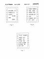
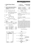
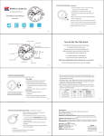
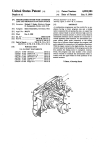
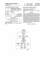
United States Patent [191
Leavell et a1.
'
[54] DEPTH FINDER WITH TUTORIAL
[75] Inventors: David R. Leavell, Columbus, Ga;
Earl W. Spencer, Jr., Montgomery,
Ala.; Bruce L. Bacon, Columbus, Ga.
[73] Assignee: Microsonics, Inc., Columbus, Ga.
[21] Appl. No.: 380,796
[22] Filed:
[11]
[45]
4,943,951
Jul. 24, 1990
Bass Pro Shops, 1988 Catalog; pp. 438-450.
The Bottom Line User Manual; 1986; pp. l-l8.
Primary Examiner—Thomas _H. Tarcza
Assistant Examiner-Tod Swann
-
Attorney, Agent, or Firm—Jennings, Carter, Thompson
& Veal
[57]
Jul. 17, 1989
Patent Number:
Date of Patent:
ABSTRACT
A liquid crystal display depth ?nder using a sonar trans
ducer is provided with a plurality of input keys inter
faced to a microprocessor with each input key being
[51]
Int. c1; ............................................ .. G01S 15/96
[52]
U.S. c1. .................................. .. 367/111; 367/107;
[58]
Field of Search ............... .. 367/99, 107, 111, 112,
dedicated to a particular function or feature usable with
[56]
367/115, 910; 434/1, 6, 10
References Cited
trol the operation of the transducer and the display of
the data generated thereby in accordance with the par
367/910; 434/6 .
U.S. PATENT DOCUMENTS
4,597,069
6/1986
Milano et a1. ................. .. 367/112 X
OTHER PUBLICATIONS
Eagle 3D-l00, Liquid Crystal Graph; Dec. 1987, pp.
142; Owners Manual.
the depth ?nder. The microprocessor is utilized to con
ticular function or set of functions chosen by the opera
tor and to manipulate programming stored within the
depth ?nder which will enable a tutorial mode compris
ing alphanumeric information and command key indica
tion such that an the user may determine how the ma
chine is to properly function.
Eagle 7-7500; Cabela’s, 1987, Christmas Catalog, 1
page.
10 Claims, 6 Drawing Sheets
US. Patent
Jul. 24, 1990
Sheet 1 of 6
4,943,951 I
Z ?vowER DISPLAY LIGHTS 1'
: ON/OFF
r '- FISH
RATE
ON/OFF ;'
RANGING
200M1 3';
'27
Zle
Aura/Mm
~4. "t%€%%
239 saws
21h +18%“
j I_ ALARM L AUTOIMAN
TIME/ALARM sew
"
US. Patent
Jul. 24, 1990
Sheet 2 of 6
4,943,951
\NITIALIZE & SHOW
LO GON
1
5E ARCH
FOR BOTTOM
II
SOUND
FOR DBPLAY
SEARCH
FOR
BOTTOM
SOUND FOR
DISPLAY
FlLTER
I TRACK
DATA
BOTTOM
V A
B L A CK
BELOW BOTTOM
‘
ADJUST
RANGE SCALE.
l
A
US. Patent
Jul. 24, 1990
Sheet 3 of 6
l
Fig. 2B
ERASE
SHALLOW CLUTTER
BOTTOM
TRACKED
> 3x ?
PREPARE SOUNDTNG
FOR
SCREEN
l
CHECK FISH ALARM
l
SCROLL D\SPLAY SCREEN
l
DTSDLAY BOTTOM SEGMENT
PUT UP
SMALL BOX MESSAGE
l
STORE SOUNDTNG DATA
1
BUZZER
OFF
D\SPLAY
TIME
l
DTSPLAY
TOP UNE SCROLUNG
l
CHECK BOTTOM ALARM
i
\F DEMO
GET DEMO BOTTOM
l
LOOK AT KEY PAD
&
D\ S P LAY
OMALL BOX MESSAGE
4,943,951
US. Patent
Jul. 24, 1990
Fig. 3
Sheet 4 of 6
START
DEMO
OPEN IN G
MODE.
MESSAGES
V
H IT
KEY
FEATURE
PROMPT
CASE!
A KEY IS HIT
I
ARROW KEY
FEATURE KEY
POWER KEY
SPECIFY FIRST PAGE
TO BE SHOWN
V
SHOW
SPECIFIED PAGE
OF TH IS FEATURE
UDISPLAY ASSIGNED ANIMATION
CASEI
WAIT ON A KEY
TO BE HIT
DIFFERENT
FEATURE KEY
SAME FECAIQ'URE KEY
DOWN ARROW
ADVANCE
TO
NEXT PAGE
A
BACK UP
TO
PREVIOUS PAGE
4,943,951
US. Patent
Jul. 24, 1990
Fig. [I-
Sheet 5 of 6
4,943,951
Power Supply
26
)
Keypad
28 A
13
Display ~f
Microprocessor
.
E P R0 M
Receiver
° Transmi’r’rer
31~ Temp. Sensor
l
Transducer
:i
\,I\/
29
US. Patent
Jul. 24, 1990
E
Sheet 6 of 6
1
4,943,951
A
.
>
W
USER GUIDEI
‘2
WELCOME TO
I
E
FOR
=
HAWKEYE'S
:1
=
PRESS ANY
=
E:
USER'S
:
:
FEATURE KEY
=
GUIDE
3
C
USE
3
DEMO
3
:
POWER
E
C
AND
.
L
'
TO
S
|NF0
g
A Fig. 5
Fig. 6
ALARMI 3
PRESS KEY
ONCE TO
':
TURN THE
2
:
FISH ALARM
:1
EITHER ON
OR OFF
Fig. 7
I,
EXIT
L
‘FISH
KEY
2”
1
4,943,951
2
may be ascertained. The depth finder may also have a
DEPTH FINDER WITH TUTORIAL
variety of sensitivity selections or functions which the
operator needs to learn. Many of these functions have
FIELD OF THE INVENTION
been enabled by the utilization of chip technology with
small computers which are actually employed in the
circuitry of the depth ?nders. Therefore, it is not un
The present invention relates to depth ?nders and
more particularly to depth ?nders which use acoustic
waves generated by a transducer mounted on a boat to
common for the ?sherman to be overmatched when
determine the depth and bottom contour of a body of
water and also to locate ?sh suspended in the body of
water. More particularly the present invention relates
‘to a depth ?nder of the type utilized by sport ?shermen
and in even greater particularity relates to a depth
?nder wherein the acoustic data retrieved by the system
dealing with his particular depth ?nder, that is to say,
is displayed on a pictorial screen such as may be gener
ated by the use of a Liquid Crystal Display (LCD). In
even greater particularity the present invention may be
the ?sherman may have more equipment than he is able
to handle while maintaining an interest in catching a
?sh. To this end, it has become apparent that the techni
cal aspects of using a depth ?nder with its various sensi
tivity and automation features has reached the level
where a need exists for a simpli?ed depth ?nder which
can perform all of the functions that a ?sherman wishes
to have performed.
described as a depth ?nder of the aforementioned type
wherein a tutorial mode is employed to provide an
on-screen alpha-numeric description and feature illus
tration presentation which allows the user to obtain
assistance in the proper utilization of the depth ?nder.
BACKGROUND OF THE INVENTION
Over the past several years the utilization of depth
?nders in locating schools of ?sh and bottom structure
has become an increasingly popular adjunct to sport
?shing. The early depth ?nders were based on the
World War II era sonar which allowed an acoustic
signal to be generated and transmitted through the wa
ter, re?ected by the bottom and returned to a sensing
device which, in combination with electronic circuitry,
was able to time the transit of the wave through the
water and judge the distance of the bottom from the
boat. Oftentimes these devices merely presented an
indication on a circular scale that stated that the bottom
was at thus and such depth and therefore it was neces
sary to pay close attention to the scale to determine
contour of the bottom of the body of water. As these
devices have progressed over the years, the state of the
art has developed to the point that it is common to
employ a recorded graph which automatically traces a
pictorial representation of the bottom of the body of
water on a strip of paper using pins or other imaging
techniques with the strip of paper being retained by the
SUMMARY OF THE INVENTION
It is an object of the present invention to provide a
depth ?nder which will enable the sport ?sherman to
easily locate bottom features and suspended ?sh while
?shing.
Yet another object of the invention is to provide a
depth
?nder of the above type which is user friendly in
25
that it will be able to assist the ?sherman in the opera
tion of the depth ?nder.
Yet another object of the invention is to provide a
depth ?nder which can be used as a training device so
that the ?sherman may become acquainted with its
various features prior to having to actually use the
depth ?nder on a body of water as well as on the water.
Yet another object of the invention is to provide a
depth ?nder which contains a built-in tutorial mode
such that the depth ?nder may teach the ?sherman how
to use the depth ?nder providing written instruction for
display on the depth ?nder along with indication illus
trations for each command key.
Accordingly, these and other objects and features of
my invention are provided in a novel combination of
technology and ingenuity wherein a liquid crystal dis
play depth ?nder using a sonar transducer is provided
with a plurality of input keys interfaced to a micro
processor with each input key being dedicated to a
operator. In these instances, of course, a permanent 45 particular function or feature usable with the depth
?nder. The microprocessor is utilized to control the
record of the bottom contour along a particular transit
operation of the transducer and the display of the data
line across the water may be recorded and preserved. It
generated thereby in accordance with the particular
will be appreciated that most ?shermen do not have a
function or set of functions chosen by the operator and
need to record each transit of the body of water but
to manipulate programming stored within the depth
rather are more particularly concerned with the sub
?nder which will enable a tutorial mode such that in
merged features of the body of water as they are mov
struction may be obtained by the user on the use of any
ing over the body of water. This is particularly true in
of the features enabled by the control keys an so that he
as much as the sensitivity of depth ?nders has been
may determine how the machine is to properly func
increased to the point where suspended objects such as
tion. The depth ?nder has a standard operational mode
?sh or schools of ?sh may be detected by the depth
wherein it is capable of providing such information as a
?nders and represented on a display screen. Therefore it
?sh alarm which provides an audible alert when ?sh are
is now popular to provide depth ?nders which have
detected, manual or automatic ranging to adjust the
display screens such as liquid crystal displays which can
depth scale, selective monitoring of a speci?ed depth of
give a pictorial representation of not only the bottom of
the body of water but also of ?sh suspended above the 60 water or of a speci?ed region of water proximal the
bottom, manual or automatic sensitivity adjustment,
bottom of the body of water.
illumination of the keypad, surface temperature, and the
The evolution of the technology has seen a corre
sponding evolution of the complexity of the data and
time and date. The display rate may also be varied, thus
information required by the ?shermen. As the technol
it may be seen that the depth ?nder is a somewhat com
ogy has grown, the ?shermen has been required to
plicated instrument. Accordingly, our invention utilizes
become increasingly adept at operating the depth
the same input function keys and the control keys which
?nder. For example, the depth ?nder may have a plural
are utilized to control each of the above described func
ity of ranges over which the depth of the body of water
tions of the depth ?nder in a tutorial or demonstration
3
4,943,951
mode, thereby allowing the ?sherman to utilize the
depth ?nder as a an instructional training device. To
accomplish this aspect of the invention, we have pro
vided a memory programmed to generate an arti?cial
display on the screen which display can be controlled
by utilization of the function keys on the depth ?nder.
Associated with each function key on the depth ?nder
and the display is information presented in graphic form
which provides a textual explanation of the utilization
of the particular function key. Thus the operator may at
4
tation covers the entire depth of water and illustrates
what that depth may be or may indicate that the picto
rial representation covers only a selected depth of water
and indicates what that depth of water may be.
Also displayed on the liquid crystal display 13 imme
- any time place the depth ?nder in the demonstration or
diately below the range numeric indicators 16 is a digi
tal bottom indicator which digitally represents the
depth of the bottom as determined by the depth ?nder
at any particular moment. The display 13 may also
indicate on its face a variable temperature display 18
which provides a Fahrenheit indication of the tempera
tutorial mode and obtain assistance in utilizing the par
ticular function key while either on the lake or other
ture of the water at the transducer and a clock display
19 which provides the current time. Of course the dis
body of water or at home or on dry land. Thus the
?sherman has no need to fumble with an instruction
manual which may become soiled, Wet or lost while he
is trying to operate his depth ?nder and catch ?sh.
Therefore the inherent frustration which accompanies
play would not be complete without a graph representa
tion 21 of the bottom 22 of the body of water and any
objects 23 which may be suspended above the bottom
22. Preferentially across the top of the display above the
graph 21 is provided a plurality of function indicators
the use of a technical device in what should be a relax
24 which inform the operator at a glance as to which
ing setting is overcome by a very simple innovation
which takes the guesswork and confusion out of operat
functions are being utilized in generating the current
display. The housing also includes a keypad indicated
ing a sophisticated depth ?nder.
generally at 26 which allows the operator to control the
functions of the depth ?nder or to select automatic
BRIEF DESCRIPTION OF THE DRAWINGS
operation of the depth ?nder. The keypad includes a
Apparatus embodying features of my invention are 25 plurality of individual keys 27, each of which is associ
depicted in the accompanying drawings which form a
ated with a particular function of the depth ?nder or a
portion of this invention and wherein:
particular control command to the depth ?nder. By
FIG. 1 is a pictorial representation of a depth ?nder
way of example, in the illustration it may be seen that
embodying my invention showing the display face and
there are three keys 27 indicated across the upper right
input keyboard of the depth ?nder;
.
30 portion of the depth ?nder. These keys correspond to a
FIGS. 20 & 2b are a simpli?ed version of a flow chart
power on/off key 27a, a display rate key 27b and a light
depicting the operation of the depth ?nder;
on/off key 270. The lower nine keys 27d-k provide
FIG. 3 is a simpli?ed version of a ?ow chart showing
input from the operator to the depth ?nder as to such
features as the ?sh alarm, the ranging, bottom tracking,
mode;
35 bottom alarm, sensitivity, the clock and controls such as
FIG. 4 is a simpli?ed block diagram of the electronic
increasing or decreasing any of the foregoing. As may
circuitry which may be used in my depth ?nder; and
be seen in FIG. 4, a microprocessor 28 operatively
FIGS. 5-7 are pictorial representations of the display
connected to the keypad 26 controls the display 13 and
while in a tutorial mode.
receives input not only from the keypad 26 but also
from a transducer 29 and a temperature sensor 31.
DESCRIPTION OF A PREFERRED
The microprocessor 28 has associated therewith vari
EMBODIMENT
ous memory or storage devices which allowed the pro
Referring to FIG. 1, it may be seen that my depth
cessor to access a set of commands to control its opera
?nder includes a housing 11 which encases the elec
tion. Thus, in FIG. 2 the microprocessor 28 will per
tronic circuitry generally depicted in FIG. 4. The hous 45 form a plurality of steps and poll each of its inputs in a
. ing 11 has attached thereto a set of mounting and adjust
speci?ed order. The preferred order, as shown in FIGS.
ment knobs which allow the depth ?nder to be mounted
2a and b is to initialize all parameters in accordance
the operation of the depth ?nder when in the tutorial
to the boat in a conventional manner and oriented as is
convenient for the ?sherman to observe the pictorial
with a predetermined set of conditions and then begin a
bottom search. As may be seen, if the bottom is not
representation of the underwater scenario as shown on 50 found, a small box message will be displayed stating that
the bottom is not found. The entire sequence below the
the display 13. The display 13 is a liquid crystal display
of the latest technology which provides the highest
degree of brightness in all light conditions and all view
ing angles. The display is bordered by a permanent
region whereon four horizontally disposed lines 14 are
search for bottom box and the top of FIG. 1a is itera
tively performed at a rate determined by the process of
selection and the circuitry associated therewith as is
55 well known in the art. Note that near the bottom of the
permanently ?xed. These lines provide a constant refer
flow chart shown in FIG. 2 the microprocessor has a
ence against which may be presented various numeric
command which says “if demo, get demo bottom” fol
indications of the depth of water being scanned by the
lowed by a command “look at keypad”. If the arrow
depth ?nder. The display itself presents numeric indica
keys are hit simultaneously, the microprocessor is
tors 16 which are positioned adjacent each of the lines
14. Thus the upper line may have the numeral 10 shown
on the display screen adjacent thereto while the second,
third and fourth lines may have the numeral 20, 30 and
placed in the demo mode and information stored in the
memory devices associated with the microprocessor
can be retrieved to generate an arti?cial display on
display 13 or textual matter associated with the function
40 respectively displayed on the display 14. Alterna
keys. If the tutorial is selected, the ?ow chart shown in
tively, other incremental depths such as 40,'60, 80 or 65 FIG. 3 represents the sequence of events which allow
110, 130, 140 may be displayed adjacent the lines 14. In
the depth ?nder to interface with the user. The ?rst
this manner, the display is able to provide an easily
page of information displayed on the display 13 when
referenced indication of whether the pictorial represen
the demonstration mode and tutorial mode is called up,
5
4,943,951
6
therein responsive to manual operation of said
is shown in FIG. 5. In the tutorial mode, the screen
presents a prompt, as in FIG. 6, to the user to press one
input means.
of the feature keys 27d-k. If the power key is hit again,
'
2. Apparatus as de?ned in claim 1 wherein said input
means is a keypad having discrete keys for each of a
number of predetermined variables and for additional
control functions.
3. Apparatus as de?ned in claim 2 including a control
key for a bottom alarm variable; a control key for a
ranging variable; and a control key for a depth bracket
the ?sh ?nder returns to its normal operating mode and
continues the iteration shown in the ?ow chart in FIG.
2. However if a feature key is hit, then a message is
retrieved from memory and displayed on the display 13
as in FIG. 7 to familiarize the user with the operation of
the feature key. Animation may also be provided such
that the function indication associated with the control
_keys may change; for example range scale may change,
the digital bottom indicator may change, the tempera
ture display may change, the bar graph 21 may change.
If the operator then hits another key 27 the micro
processor will provide the user with further information
variable.
>
4. Apparatus as de?ned in claim 2 wherein said dis
play means comprises an LCD screen having a ?xed
border thereabout, said border providing a plurality of
?xed indicia and said LCD providing selected depth
indicia adjacent said ?xed indicia in accordance with
signals provided from said processing means.
if the same is available or will return'the user to the
main menu such that another feature key may be se
5. Apparatus as de?ned in claim 1 wherein said means
lected for tutorial assistance therewith.
From the foregoing it may be seen that the depth
for providing a simulated graphic display comprises an
electronic read only memory operatively connected to
?nder allows the ?sherman to refresh himself on the
said programmable computer means and having an
capabilities of the depth ?nder while on the water. For
_ executable program stored therein which is executable
example, if the ?sherman normally uses the depth ?nder
in the bottom tracking mode, but decides he wishes to
look at a different layer of water, he may go to the user’s
guide to check on how the machine functions in that
mode prior to selecting the mode. Thus, all he has to do
to ensure proper operation is to enable the user’s guide
and push the key corresponding to the function he de
sires. The machine will then display the information
needed for him to properly use this function of the
on command input via said input means to present on
said display means a selected representation of imagery
associated with predetermined operating parameters of
said apparatus.
6. Apparatus as de?ned in claim 5 wherein said input
means is a keypad including a plurality of keys for con
trolling or modifying the operation of said apparatus.
7. A depth ?nder for locating underwater structure
and ?sh from a floating platform by directing sonic
device. He can then return to the operational mode and
energy downwater into a subjacent body of water com
prising:
utilize the information which he has reviewed.
While I have shown my invention in one form, it will
(a) electronic means for generating and receiving a
series of identi?able repetitive sonic signals;
(b) programmable computer means operatively con
be obvious to those skilled in the art that it is not so
limited but is susceptible of various changes and modi?
cations without departing from the spirit thereof.
nected to said electronic means to receive data
What I claim is:
therefrom relative to said sonic signals, said pro
grammable computer means programmed to utilize
said data to generate electronic signals representa
1. A depth ?nder for use on a boat to locate underwa
ter structure and ?sh using reflected sonic energy com
prising:
tive of underwater structure and ?sh in a live oper
(a) transmitter means for generating repetitive sig
ating mode;
nals;
(c) programmable memory means for use in an inter
(b) transducer means for converting said signals into
sonic energy and directing said energy into a body
active tutorial mode of operation wherein an oper
ator is provided with instruction on the operation
of water such that re?ected sonic energy incident
on said transducer means is converted into a re 45
?ected energy signal;
(0) receiver means for receiving said re?ected energy
signal;
therewith; and
((1) programmable cotnputer means operatively con
(e) input means operatively connected to said pro
grammable controller to allow an operator provide
nected to said transmitter means and said receiver
means to receive electronic information therefrom
control messages thereto to select the mode of
operation of said depth ?nder and to interactively
control said operation.
and to provide control signals thereto in accor
dance with a plurality of operating modes pro
grammed within said programmable computer
means;
8. Apparatus as de?ned in claim 7 wherein said input
55 means comprises a keypad operatively ‘connected to
(e) display means operatively connected to said pro
grammable computer means for displaying visual
graphic representations corresponding to said re
?ected energy signal;
(f) manually operable input means for providing com
mand signals to said programmable computer
means; and
(g) means associated with said programmable com
puter means for providing a tutorial display on said
display means to explain the proper operation of
said depth ?nder, said means being interactive with
said input means and said programmable computer
means to display instructional information stored
of said depth ?nder;
(d) display means operatively connected to said pro
grammable computer means to receive electronic
signals and provide a visual display in accordance
said programmable computer means to selectively con
trol operation of said depth ?nder, to vary the visual
display provided by said display means in each of said
modes of operation; and to selectively activate any of a
60
plurality of operating options for said programmable
computer means.
9. Apparatus as de?ned in claim 8 wherein said dis
play means comprises an LCD display wherein said
electronic signals are display graphically.
10. Apparatus as de?ned in claim 9 wherein a portion
of said LCD display is utilized to present information
indicating the selected operating options.
*
l
*
II
#