1
Kramer Electronics, Ltd.
USER MANUAL
Model:
VP-8x4AK
8x4 VGA / UXGA / Audio Matrix Switcher
Contents
Contents
1
2
2.1
3
3.1
3.2
3.3
4
4.1
5
6
6.1
6.2
6.3
6.4
Introduction
Getting Started
Quick Start
Overview
Terminology Used in this User Manual
DDC Support
Defining EDID
Your VP-8x4AK 8x4 VGA / UXGA / Audio Matrix Switcher
Using the IR Transmitter
Installing the VP-8x4AK in a Rack
Using the VP-8x4AK
Connecting the VP-8x4AK Rear Panel
Connecting the Balanced/Unbalanced Stereo Audio Output
Connecting a PC or Controller to the RS-232 Port
Connecting a PC or Controller to the RS 485 Port
1
1
1
3
4
5
5
5
9
10
11
11
13
13
14
6.4.1
Setting the VP-8x4AK
14
6.5
Configuring the Ethernet Port
15
6.5.1
6.5.2
Connecting via the Ethernet
Ethernet Port Configuration
15
17
6.6
6.7
6.8
6.9
7
7.1
7.2
Control via the Ethernet Port
Setting the Switching Delay Time
Setting the Machine Number
Cascading Machines
Operating the VP-8x4AK
Switching an Input to an Output
Understanding the 7-Segment Displays
18
19
19
19
21
21
21
7.2.1
7.2.2
The STATUS 7-Segment Display
The REL AUDIO LEVEL 7-Segment Display
21
22
7.3
Confirming Settings
22
7.3.1
7.3.2
Toggling between the At Once and Confirm Modes
Confirming a Switching Action
22
23
7.4
Storing/Recalling Input/Output Configurations
23
7.4.1
7.4.2
Storing an Input/Output Configuration
Recalling an Input/Output Configuration
23
24
7.5
7.6
Locking the Front Panel
Choosing the Audio-Follow-Video or Breakaway Option
24
24
7.6.1
7.6.2
Setting the Audio-Follow-Video Option
Setting the Breakaway Option
25
25
i
Contents
7.7
8
9
9.1
9.2
The Audio Input/Output Gain Control
Flash Memory Upgrade
Controlling via the Embedded Web Pages
Connecting to the VP-8x4AK via your Browser
The VP-8x4AK Switching Matrix Page
25
26
26
27
28
9.2.1
9.2.2
9.2.3
Switch an Input to an Output via the Embedded Web Pages
Operate in the Confirm Mode
Store and Recall Setups
29
30
31
9.3
9.4
10
11
12
13
14
14.1
Audio Gain Page
The Configurations Page
Technical Specifications
Communication Parameters
Table of ASCII Codes for Serial Communication (Protocol 3000)
Hex Codes for Serial Communication (Protocol 2000)
Kramer Protocol
Switching Protocols
33
34
35
36
37
38
40
40
14.1.1 Switching Protocols via the Front Panel Buttons
14.1.2 Switching Protocols via Protocol Commands
40
40
14.2
Kramer Protocol 3000
40
14.2.1 Protocol 3000 Syntax
14.2.2 Command Parts Details
41
42
14.3
48
Kramer Protocol 2000
Figures
Figure 1: VP-8x4AK 8x4 VGA / UXGA / Audio Matrix Switcher – Front View
Figure 2: VP-8x4AK 8x4 VGA / UXGA / Audio Matrix Switcher – Rear View
Figure 3: Connecting the VP-8x4AK 8x4 VGA / UXGA / Audio Matrix Switcher
Figure 4: Connecting a Balanced Stereo Audio Output
Figure 5: Connecting an Unbalanced Stereo Audio Output
Figure 6: The RS-485 TERM DIP-switch
Figure 7: Local Area Connection Properties Window
Figure 8: Internet Protocol (TCP/IP) Properties Window
Figure 9: Connect Screen
Figure 10: Device Properties Screen
Figure 11: Control Configuration via RS-232 and RS-485
Figure 12: 7-segment Display during Normal Operation
Figure 13: REL AUDIO LEVEL 7-segment Display
Figure 14: Storing and Recalling using the Input/Output Buttons
Figure 15: Java Test Page Success Message
Figure 16: Entering the IP Number in the Address Bar
Figure 17: Loading the Embedded Web Pages
Figure 18: First Time Security Warning
Figure 19: VP-8x4AK Embedded Web Page
ii
6
8
12
13
13
14
16
16
17
18
20
21
22
23
26
27
27
28
29
KRAMER: SIMPLE CREATIVE TECHNOLOGY
Contents
Figure 20: Switching an Input to an Output
Figure 21: Switching an Input to an Output in the Confirm Mode
Figure 22: Exiting Offline Warning
Figure 23: Selecting a preset
Figure 24: Save Preset Message
Figure 25: Load Preset Message
Figure 26: Recalling a Preset in the Confirm Mode
Figure 27: Audio Gain
Figure 28: CONFIGURATIONS Embedded Web Page
30
30
31
31
32
32
33
33
34
Tables
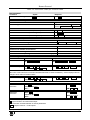
Table 1: Terminology Used in this User Manual
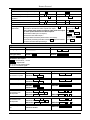
Table 2: Front Panel VP-8x4AK 8x4 VGA / UXGA / Audio Matrix Switcher Features
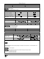
Table 3: Rear Panel VP-8x4AK 8x4 VGA / UXGA / Audio Matrix Switcher Features
Table 4: Technical Specifications of the VP-8x4AK 8x4 Video Audio Matrix Switcher
Table 5: Communication Parameters
Table 6: VP-8x4AK Video Signal Codes for Protocol 3000
Table 7: VP-8x4AK Audio Signal Codes for Protocol 3000
Table 8: VP-8x4AK Audio Input Gain Codes
Table 9: VP-8x4AK Audio Output Gain Codes
Table 10: VP-8x4AK Hex Codes for Switching via RS-232/RS-485
Table 11: VP-8x4AK Hex Codes for Switching Audio Channels via RS-232/RS-485
Table 12: VP-8x4AK Hex Codes for Increasing/Decreasing the Audio Input Gain
Table 13: VP-8x4AK Hex Codes for Setting the Audio Input Gain
Table 14: VP-8x4AK Hex Codes for Increasing/Decreasing the Output Gain
Table 15: VP-8x4AK Hex Codes for Setting the Audio Output Gain
Table 16: Instruction Codes for Protocol 3000
Table 17: Protocol Definitions
Table 18: Instruction Codes for Protocol 2000
4
7
9
35
36
37
37
37
38
38
38
39
39
39
39
43
48
49
iii
Introduction
1
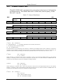
Introduction
Welcome to Kramer Electronics! Since 1981, Kramer Electronics has been
providing a world of unique, creative, and affordable solutions to the vast range
of problems that confront the video, audio, presentation, and broadcasting
professional on a daily basis. In recent years, we have redesigned and upgraded
most of our line, making the best even better! Our 1,000-plus different models
now appear in 11 groups 1 that are clearly defined by function.
Congratulations on purchasing your VP-8x4AK 8x4 VGA / UXGA / Audio
Matrix Switcher, which is ideal for the following typical applications:
• Professional display systems requiring a true 8x4 computer graphics and
audio matrix operation
• Multimedia and presentation source, and acceptor selection
The package includes the following items:
• VP-8x4AK 8x4 VGA / UXGA Matrix Switcher
• Windows®-based Kramer control software 2
• Kramer RC-IR3 Infrared Remote Control Transmitter (including the
required battery and a separate user manual4)
• Power cord 3, rack “ears” and this user manual 4
2
Getting Started
We recommend that you:
• Unpack the equipment carefully and save the original box and packaging
materials for possible future shipment
• Review the contents of this user manual
• Use Kramer high performance high-resolution cables 5
2.1
Quick Start
This quick start chart summarizes the basic setup and operation steps.
1 GROUP 1: Distribution Amplifiers; GROUP 2: Switchers and Matrix Switchers; GROUP 3: Control Systems; GROUP 4:
Format/Standards Converters; GROUP 5: Range Extenders and Repeaters; GROUP 6: Specialty AV Products; GROUP 7:
Scan Converters and Scalers; GROUP 8: Cables and Connectors; GROUP 9: Room Connectivity; GROUP 10: Accessories
and Rack Adapters; GROUP 11: Sierra Products
2 Downloadable from our Web site at http://www kramerelectronics com
3 We recommend that you use only the power cord that is supplied with this machine
4 Download up-to-date Kramer user manuals from our Web site at http://www kramerelectronics com
5 The complete list of Kramer cables is on our Web site at http://www kramerelectronics com
1
Getting Started
2
KRAMER: SIMPLE CREATIVE TECHNOLOGY
Overview
3
Overview
The VP-8x4AK is a high performance 8x4 computer graphics video matrix
switcher for high-resolution video and stereo audio signals. The VP-8x4AK
is HDTV compatible and lets you route any combination of inputs and
outputs.
In particular, the VP-8x4AK 8x4 VGA / UXGA / Audio Matrix Switcher
features:
• Kramer’s innovative integrated sync processing; Kr-isp® technology that
lets you achieve a sharp, stable image when the sync level is too low, by
restoring the sync signal waveform
• A video bandwidth of over 360MHz that ensures transparent performance
even in the most critical applications
• 16 preset memory locations for quick access to common video and audio
configurations and audio gain status for each output
• Automatic detection of the connected input signals (the respective button
illuminates)
•
•
•
•
•
•
•
•
•
•
•
1
A delayed switching mode (ranging from 0 to 3.5sec ) for clean
transitions when switching between non-genlocked sources
DC-coupled video inputs and outputs
Audio-follow-video and breakaway options
Eight stereo unbalanced stereo audio input signals on 3.5mm mini plugs
Four balanced stereo audio output signals on 5-pin terminal block
connectors
Audio level control buttons for adjusting the signal level of each input
and each output
Measurement and indication of the audio level for each input and output,
in relative dB
A TAKE button, which allows you to place multiple switches in a queue
and then activate them simultaneously with one touch of this button
A LOCK button to prevent tampering with the front panel
Support for DDC (Display Data Channel) communication between selected
input 1 and output 1 high-density 15-pin HD connectors on pins 12 and 15
Control via embedded Web pages
1 In increments of 0 5sec
3
Overview
Control the VP-8x4AK using the front panel buttons, or remotely via:
• RS-485 or RS-232 serial commands (using Kramer 2000 and 3000
protocols) transmitted by a touch screen system, PC, or other serial
controller
• The Kramer infrared remote control transmitter or infrared remote
extension cable transmitter (optional)
• The ETHERNET
The VP-8x4AK is dependable, rugged, and fits into two vertical spaces (2U)
of a standard 19” professional rack.
To achieve the best performance:
• Use only good quality connection cables 1 to avoid interference,
deterioration in signal quality due to poor matching, and elevated noise
levels (often associated with low quality cables).
• Avoid interference from neighboring electrical appliances that may
adversely influence signal quality and position your Kramer VP-8x4AK
away from moisture, excessive sunlight and dust
3.1
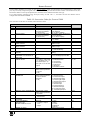
Terminology Used in this User Manual
Table 1 defines some terms that are used in this user manual:
Table 1: Terminology Used in this User Manual
Term
Definition
802.3
The standard specification for ETHERNET that is maintained by the Institute of Electrical and
Electronics Engineers (IEEE).
Dynamic Host Configuration Allows the network administrator to distribute P addresses from a central point and
Protocol (DHCP)
automatically send a new IP address when an Ethernet point is plugged into a different
network location.
Gateway
A network position serving as an entry to another network. On the Internet, a node or
stopping point can be either a gateway node or a host (end-point) node.
IP Address
A 32-binary digit number that identifies each sender or receiver (within a network via a
particular server or workstation) of data (HTML pages or e-mails) that is sent in packets
across the Internet. Every device connected to an P network must have a unique IP
address. This address is used to reference the specific unit.
Local Area Network (LAN)
Computers sharing a common communications line or wireless link, which often share a
server within a defined geographic area.
Media Access Control
A computer's unique hardware number (or address) in a LAN or other network. On an
(MAC) Address
Ethernet LAN, the (MAC) address is identical to the Ethernet address.
Transmission Control
The basic communication language or protocol of the Internet that breaks the message into
Protocol/Internet Protocol
appropriately sized packets for the network, and can be used as a communications protocol
(TCP/IP)
in an intranet or an extranet.
1 Available from Kramer Electronics on our Web site at http://www kramerelectronics com
4
KRAMER: SIMPLE CREATIVE TECHNOLOGY
Your VP-8x4AK 8x4 VGA / UXGA / Audio Matrix Switcher
3.2 DDC Support
When establishing a VGA connection between a PC or laptop and a display
device, a set of parameters known as EDID is exchanged between them,
which is carried over the DDC channel. In some PC graphic cards and
laptops, this information exchange is essential for proper VGA OUT
operation.
3.3 Defining EDID
The Extended Display Identification Data (EDID 1) is a data-structure,
provided by a display, to describe its capabilities to a graphics card (that is
connected to the display’s source). The EDID enables the PC or laptop to
“know” what kind of monitor is connected to the output. The EDID includes
the manufacturer’s name, the product type, the timing data supported by the
display, the display size, luminance data and (for digital displays only) the
pixel mapping data.
Note that EDID is supported between the input 1 and output 1 high-density
15-pin HD connectors on pins 12 and 15.
4
Your VP-8x4AK 8x4 VGA / UXGA / Audio Matrix Switcher
Figure 1, Figure 2, Table 2, and Table 3 define the VP-8x4AK 8x4 VGA /
UXGA / Audio Matrix Switcher.
1 Defined by a standard published by the Video Electronics Standards Association (VESA)
5
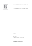
Your VP-8x4AK 8x4 VGA / UXGA / Audio Matrix Switcher
Figure 1: VP-8x4AK 8x4 VGA / UXGA / Audio Matrix Switcher – Front View
6
KRAMER: SIMPLE CREATIVE TECHNOLOGY
Your VP-8x4AK 8x4 VGA / UXGA / Audio Matrix Switcher
Table 2: Front Panel VP-8x4AK 8x4 VGA / UXGA / Audio Matrix Switcher Features
#
1
2
3
4
Feature
IR Receiver
POWER LED
SELECTOR OUT
Buttons
SELECTOR IN
Buttons
5
6
ALL Button
OFF Button
7
VIDEO Button
8
AUDIO Button
9
AFV Button
10
STO (Store) Button
11
RCL (Recall) Button
12
TAKE Button
13
14
15
16
AUDIO
LEVEL
17
- Button
+ Button
LOCK Button
STATUS 7-segment
display
REL. AUDIO LEVEL
7-segment display
Function
The yellow LED is illuminated when receiving signals from the infrared
remote control transmitter
The green LED is illuminated when the unit is turned ON
Select the output (from 1 to 4) to which the input is switched
Select the input (from 1 to 8) to switch to the output (after selecting an
output).
When a signal is detected at an input connector, the corresponding input
button is illuminated
1
Pressing ALL followed by an INPUT button, connects that input to all outputs
Press an OUT SELECTOR button and then an OFF button to disconnect that
output from the inputs.
Press the ALL button and then the OFF button to disconnect all he outputs
When pressed 2 actions relate to video. Press the VIDEO Button together with
the AUDIO button to set the Switching delay time (see Section 6.7)
3
When pressed actions relate to audio. Press the VIDEO Button toge her
with the AUDIO button to set the Switching delay time (see Section 6.7)
When pressed, the audio channels follow the video channels. The button is
illuminated when the AFV mode is selected
4
Pressing STO followed by an input/output button stores the current setting .
Press the RCL Button together with the STO button to set the machine
number (see Section 6.8)
Pressing the RCL button and the corresponding IN/OUT button recalls a setup
from the non-volatile memory.
Press the RCL button again to implement the new status.
Press the RCL Button together with the STO button to set the machine
number (see Section 6.8)
5
Pressing TAKE toggles the mode between the Confirm mode and the
At Once mode (user confirmation per action is unnecessary). When in Confirm
mode, pressing the TAKE button will implement a pending configuration
Press to decrease the input or output audio signal level
Press to increase the input or output audio signal level
Disengages the front panel switches
Displays the selected INPUT switched to the OUTPUT (marked above each
input) 6
Displays 7 the relative 8 audio level 9
1 For example, press ALL and then Input button # 2 to connect input # 2 to all the outputs
2 The VIDEO button is illuminated when in breakaway mode and actions relate to video
3 The AUDIO button is illuminated when in breakaway mode and actions relate to audio
4 For example, press STO and then the output button # 3 to store in Setup # 3, or the input button 4 to store in Setup 12
5 When in the Confirm mode, the TAKE button illuminates
6 Also displays the number of INPUT and OUTPUT ports, the firmware version number, and the MACHINE # Refer to Section 7 2 1
7 A dot following the number represents a value of 0 5 For example, 3 5 displays as "3 "
8 The audio level range is relative, since the audio input signal can be adjusted separately via trimmers on the rear panel
9 The input audio level ranges from -100dB to +20dB and the output audio level ranges from -100dB to +7 5dB
7
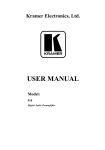
Your VP-8x4AK 8x4 VGA / UXGA / Audio Matrix Switcher
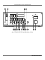
Figure 2: VP-8x4AK 8x4 VGA / UXGA / Audio Matrix Switcher – Rear View
8
KRAMER: SIMPLE CREATIVE TECHNOLOGY
Your VP-8x4AK 8x4 VGA / UXGA / Audio Matrix Switcher
Table 3: Rear Panel VP-8x4AK 8x4 VGA / UXGA / Audio Matrix Switcher Features
#
3
4
5
6
Feature
AUDIO INPUT 3.5mm Mini
Connectors
AUDIO OUTPUT Terminal Block
Connectors
Power Switch
INPUT 15-pin HD Connectors
OUTPUT 15-pin HD Connectors
PROGRAM Button
7
RS-485 TERM DIP-switch
8
9
RS-232 9-pin D-sub Port
REMOTE IR Opening 2
10
FACTORY RESET Button
11
12
ETHERNET Connector
RS-485 Terminal Block Port
13
Power Connector with Fuse
1
2
4.1
Function
Connect to the unbalanced stereo audio acceptors (from 1 to 8)
Connect to balanced stereo audio sources (from 1 to 4)
Illuminated switch for turning the unit ON or OFF
Connect to the video sources (from 1 to 8)
Connect to the output acceptors (from 1 to 4)
Push in for “Program” to upgrade to the latest Kramer firmware via
RS-232 (see Section 8), or release for “Normal” (the factory default)
1
Use for RS-485 Termination : ON for RS-485 Line Termination with
120Ω; OFF for no RS-485 Line Termination
Connects to the PC or the remote controller
Connects to an external IR receiver unit for controlling the machine via
an IR remote controller instead of using the front panel IR receiver 3
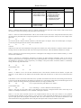
4
Press to reset to factory default definitions :
IP Address:
192.168.1.39
Mask:
255.255.255.0
Gateway:
192.168.1.1
Connects to the PC or other serial controller through computer networking
Pins B (-) and A (+) are for RS-485; Pin G (Ground) may be
connected to the shield of the cable if desired
AC connector enabling power supply to the unit
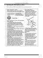
Using the IR Transmitter
You can use the RC-IR3 IR transmitter to control the machine via the built-in
IR receiver on the front panel or, instead, via an optional external IR
receiver 5. The external IR receiver can be located up to 15 meters away from
the machine. This distance can be extended to up to 60 meters when used
with three extension cables 6
Before using the external IR receiver, be sure to arrange for your Kramer
dealer to insert the internal IR connection cable 7 with the 3.5mm connector
that fits into the REMOTE IR opening on the rear panel. Connect the external
IR receiver to the REMOTE IR 3.5mm connector.
23F
1 The first and the last units on the RS-485 line should be terminated (ON). Other units should be unterminated (OFF)
2 Covered by a cap. The 3.5mm connector at the end of the internal IR connection cable fits through this opening
3 Optional. Can be used instead of the front panel (built-in) IR receiver to remotely control the machine (only if the internal
IR connection cable has been installed)
4 Turn the machine OFF using the power switch and then turn it ON while pressing the ETH Factory Reset button. The unit
will power up and load its memory with the factory default definitions
5 Model: C-A35M/IRR-50
6 Model: C-A35M/A35F-50
7 P/N: 505-70434010-S
9
Installing the VP-8x4AK in a Rack
5
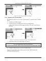
Installing the VP-8x4AK in a Rack
This section provides instructions for rack mounting the unit.
10
KRAMER: SIMPLE CREATIVE TECHNOLOGY
Using the VP-8x4AK
6
Using the VP-8x4AK
This section describes how to:
• Connect the VP-8x4AK rear panel (see Section 6.1)
• Connect a balanced stereo audio output (see Section 6.2)
• Connect the VP-8x4AK to a controlling device via RS-232 (see Section
6.3), RS-485 (see Section 6.4) and/or the ETHERNET (see Section 6.5)
• Set the switching delay time (see Section 6.7)
• Set the machine number (see Section 6.8)
• Connect several VP-8x4AK machines (see Section 6.9)
6.1
Connecting the VP-8x4AK Rear Panel
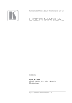
To connect 1 the VP-8x4AK, as illustrated in the example in Figure 3, do the
following 2:
1. Connect up to eight VGA/UXGA computer graphics sources to the
INPUT 15-pin HD connectors.
2. Connect up to eight unbalanced stereo audio sources (for example, the
audio source of the computer, or a stereo audio source) to the eight
INPUT 3.5mm mini connectors.
3. Connect the eight OUTPUT 15-pin HD connectors to up to eight
VGA/UXGA video acceptors (for example, displays).
4. Connect the eight OUTPUT terminal block connectors to up to eight
balanced stereo audio acceptors (for example, balanced stereo audio
amplifiers with speakers).
5. If required, you can connect a PC and/or controller to the:
RS-232 port (see Section 6.3)
RS-485 port (see Section 6.4)
ETHERNET (see Section 6.5)
6. Connect the power cord (not shown in Figure 3) 3.
1 You do not need to connect all inputs and outputs
2 Switch OFF the power on each device before connecting it to your VP-8x4AK After connecting your VP-8x4AK, switch
on its power and then switch on the power on each device DO NOT push in the rear panel Flash Program “PROGRAM”
button , it is only used for upgrading to the latest Kramer firmware
3 We recommend that you use only the power cord that is supplied with this machine
11
Using the VP-8x4AK
Figure 3: Connecting the VP-8x4AK 8x4 VGA / UXGA / Audio Matrix Switcher
12
KRAMER: SIMPLE CREATIVE TECHNOLOGY
Using the VP-8x4AK
6.2
Connecting the Balanced/Unbalanced Stereo Audio Output
This section illustrates how to wire:
• A balanced output connection, see Figure 4
• An unbalanced audio output, see Figure 5
Figure 4: Connecting a Balanced Stereo Audio Output
Figure 5: Connecting an Unbalanced Stereo Audio Output
6.3
Connecting a PC or Controller to the RS-232 Port
You can connect to the VP-8x4AK via an RS-232 connection using, for
example, a PC. Note that a null-modem adapter/connection is not required.
To connect to the VP-8x4AK via RS-232:
• Connect the RS-232 9-pin D-sub rear panel port on the product unit via a
9-wire straight cable (only pin 2 to pin 2, pin 3 to pin 3, and pin 5 to pin 5
need to be connected) to the RS-232 9-pin D-sub port on your PC
13
Using the VP-8x4AK
6.4
Connecting a PC or Controller to the RS 485 Port
You can operate the VP-8x4AK via the RS-485 port from a distance of up to
1200m (3900ft) using any device equipped with an RS-485 port (for example,
a PC). For successful communication, you must set the RS-485 machine
number and bus termination.
To connect a device with a RS-485 port to the VP-8x4AK:
• Connect the A (+) pin on the RS-485 port of the PC to the A (+) pin on
the RS-485 port on the rear panel of the VP-8x4AK
• Connect the B (–) pin on the RS-485 port of the PC to the B (–) pin on the
RS-485 port on the rear panel of the VP-8x4AK
• Connect the G pin on the RS-485 port of the PC to the G pin on the
RS-485 port on the rear panel of the VP-8x4AK
6.4.1 Setting the VP-8x4AK
1. Set the VP-8x4AK unit to a Machine # other than 1, according to Section
6.8.
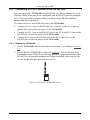
2. Set the RS-485 TERM DIP-switch (see Figure 6 ) ON (for RS-485 Line
Termination with 120Ω) if it is the only machine being controlled via this
RS-485 line (if multiple machines are being controlled, then only the last
one on the RS-485 line should be set to ON).
Figure 6: The RS-485 TERM DIP-switch
14
KRAMER: SIMPLE CREATIVE TECHNOLOGY
Using the VP-8x4AK
6.5 Configuring the Ethernet Port
To configure the Ethernet port, you have to connect your PC to the
VP-8x4AK either via the Ethernet (see Section 6.5.1) or via a serial port.
Once the machine is connected, you can configure the Ethernet port.
6.5.1
Connecting via the Ethernet
You can connect the VP-8x4AK via the ETHERNET in the following ways:
• For direct connection to the PC, use a crossover cable (see Section
6.5.1.1)
• For connection via a network hub or network router, use a
straight-through cable (see Section 6.5.1.2)
6.5.1.1 Connecting the ETHERNET Port Directly to a PC (Crossover Cable)
You can connect the Ethernet port of the machine to the Ethernet port on your
PC, via a crossover cable with RJ-45 connectors.
This type of connection is recommended for identification of the factory default
1
IP Address of the VP-8x4AK during the initial configuration
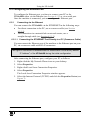
After connecting the Ethernet port, configure your PC as follows:
1. Right-click the My Network Places icon on your desktop.
2. Select Properties.
3. Right-click Local Area Connection Properties.
4. Select Properties.
The Local Area Connection Properties window appears.
5. Select the Internet Protocol (TCP/IP) and click the Properties Button (see
Figure 7).
1 The default IP address is 192 168 1 39
15
Using the VP-8x4AK
Figure 7: Local Area Connection Properties Window
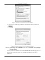
6. Select Use the following IP Address, and fill in the details as shown in
Figure 8.
7. Click OK.
Figure 8: Internet Protocol (TCP/IP) Properties Window
6.5.1.2 Connecting the ETHERNET Port via a Network Hub (StraightThrough Cable)
You can connect the Ethernet port of the VP-8x4AK to the Ethernet port on a
network hub or network router, via a straight-through cable with RJ-45
connectors.
16
KRAMER: SIMPLE CREATIVE TECHNOLOGY
Using the VP-8x4AK
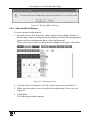
6.5.2
Ethernet Port Configuration
To configure the Ethernet port, download the P3K Wizard Ethernet
configuration software. Extract the file to a folder and create a shortcut on
your desktop to the file.
Follow these steps to configure the port:
1. Double click the desktop icon.
The Connect screen appears as follows:
Figure 9: Connect Screen
2. Select the method to connect to the Ethernet port of the VP-8x4AK.
Select:
Ethernet, if you know the IP address number 1 or the machine name.
The default name for the machine is KRAMER_XXXX 2
Serial, if you are connected via a serial port
3. Click OK.
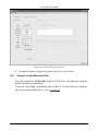
The Device Properties window appears:
1 The default IP address is 192 168 1 39
2 The four digits are the last four digits of the machine’s serial number
17
Using the VP-8x4AK
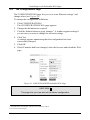
Figure 10: Device Properties Screen
4. If required, make changes and press Set. If not, click Close.
6.6
Control via the Ethernet Port
You can control the VP-8x4AK via RS-232/RS-485 or the Ethernet using the
Kramer K-Router application.
If you are controlling a standalone unit via RS-232 or the Ethernet, configure
the unit as master (Mach No. 1), see Section 6.8.
18
KRAMER: SIMPLE CREATIVE TECHNOLOGY
Using the VP-8x4AK
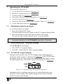
6.7 Setting the Switching Delay Time
You can achieve clean transitions when switching between non-genlocked
sources by setting the delay time—ranging from 0sec to 3.5sec 1. The factory
default delay is to 0sec.
To set the delay time, do the following:
1. Press the VIDEO and AUDIO front panel buttons simultaneously.
The 7-segment display shows the current switching delay time.
2. Use the + and – front panel buttons to set the delay time as required.
To exit the Delay mode, press the TAKE front panel button.
6.8 Setting the Machine Number
The MACH. # (machine number) determines the position of a VP-8x4AK
unit when cascading units.
To set the MACH. #, do the following:
1. Press the STO and RCL front panel buttons simultaneously.
The 7-segment display shows the current machine number.
2. Use the + and – front panel buttons to set the machine number as
required.
To exit the MACH. # mode, press the TAKE front panel button.
6.9
Cascading Machines
You can cascade up to 16 VP-8x4AK units with control from a PC or serial
controller.
To cascade up to 16 individual VP-8x4AK units via RS-485 (as illustrated in
Figure 11), do the following:
1. Connect the sources and acceptors, as Section 6.1 describes.
2. Connect the RS-232 port 2 of the first VP-8x4AK unit to a PC.
3. Connect the RS-485 terminal block port on the first unit to the RS-485
port on the second VP-8x4AK unit and so on, connecting all the RS-485
ports.
1 In increments of 0 5sec
2 Alternatively, the ETHERNET port could be used for PC control (instead of RS-232)
19
Using the VP-8x4AK
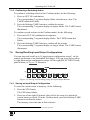
4. Set the machine numbers of the connected machines, as described in
Section 6.8, by set the first VP-8x4AK unit as Machine # 1 and the
following 15 VP-8x4AK units as Machine # 2 to Machine # 16.
5. Set the RS-485 TERM DIP-switch ON on the first and last VP-8x4AK
units (terminating the RS-485 line at 120Ω). Set the RS-485 TERM
DIP-switch OFF on the other VP-8x4AK units.
Machine # 1 (Master)
Machine # 2
Up to 16
Units
Machine # 16
Figure 11: Control Configuration via RS-232 and RS-485
20
KRAMER: SIMPLE CREATIVE TECHNOLOGY
Operating the VP-8x4AK
7
Operating the VP-8x4AK
This section describes how to:
• Use the IN and OUT buttons (see Section 7.1)
• Read the 7-segment displays (see Section 7.2)
• Confirm settings (see Section 7.3)
• Store and recall input/output configurations (see Section 7.4)
• Lock the front panel (see Section 7.5)
• Choose the audio-follow-video or the breakaway feature (see Section 7.6)
• Use the audio gain control (see Section 7.7)
7.1
Switching an Input to an Output
To switch an input to an output:
1. Press the required OUT button.
The input under the selected output on the IN 7-segment display blinks.
2. Press an IN button to select the input to switch to the output.
The selected input number appears on the 7-segment display.
Incomplete operations on the VP-8x4AK timeout after 15 seconds
7.2
Understanding the 7-Segment Displays
The VP-8x4AK has two displays:
• The STATUS 7-segment display
• The REL. AUDIO LEVEL (dB) 7-segment display
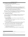
7.2.1 The STATUS 7-Segment Display
During normal operation, the STATUS display shows which inputs are
switched to which outputs, as illustrated in Figure 12. In the VIDEO mode,
the display shows the video signal setup and in the AUDIO mode, it shows
the audio signal setup. In the AFV it shows both signals (see Section 7.6).
Figure 12: 7-segment Display during Normal Operation
Immediately after switching on the power, the status display shows the
firmware version number. This display disappears after a few seconds,
replaced by the normal display.
21
Operating the VP-8x4AK
7.2.2 The REL AUDIO LEVEL 7-Segment Display
The REL AUDIO LEVEL display, as illustrated in Figure 13 (see Section
7.7).
Figure 13: REL AUDIO LEVEL 7-segment Display
7.3
Confirming Settings
You can choose to work in the At Once or the Confirm mode.
In the At Once mode (TAKE button does not illuminate):
• Pressing an OUT-IN combination implements the switch immediately
• You save time as execution is immediate and actions require no user
confirmation
• No protection is offered to allow the correction of an erroneous action before
it is implemented
In the Confirm mode (TAKE button illuminates):
• You can key-in several actions and then confirm them by pressing the TAKE
button, to simultaneously activate the multiple switches
• Every action requires user confirmation, protecting against erroneous
switching
• Execution is delayed 1 until the user confirms the action
7.3.1 Toggling between the At Once and Confirm Modes
To toggle between the At Once and Confirm modes, do the following:
1. Press the TAKE button to toggle from the At Once mode (in which the
TAKE button does not illuminate) to the Confirm mode (in which the
TAKE button illuminates).
Actions now require user confirmation and the TAKE button illuminates.
2. Press the illuminated TAKE button to toggle from the Confirm mode
back to the At Once mode.
Actions no longer require user confirmation and the TAKE button no
longer illuminates.
1 Failure to press the TAKE button within 40 seconds (the Timeout) will abort the action
22
KRAMER: SIMPLE CREATIVE TECHNOLOGY
Operating the VP-8x4AK
7.3.2 Confirming a Switching Action
To confirm a switching action (in the Confirm mode), do the following:
1. Press an OUT-IN combination.
The corresponding 7-segment display blinks with the new value. The
TAKE button also blinks.
2. Press the blinking TAKE button to confirm the action.
The corresponding 7-segment display no longer blinks. The TAKE button
illuminates.
To confirm several actions (in the Confirm mode), do the following:
1. Press each OUT-IN combination in sequence.
The corresponding 7-segment display blinks. The TAKE button also
blinks.
2. Press the blinking TAKE button to confirm all the actions.
The corresponding 7-segment display no longer blinks. The TAKE button
illuminates.
7.4
Storing/Recalling Input/Output Configurations
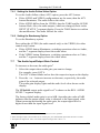
You can store and recall up to 16 input/output configuration setups 1 via the
control application or the embedded Web pages. You can store and recall up
to eight input/output configuration setups via the eight SELECTOR IN front
panel buttons, as Figure 14 illustrates:
Figure 14: Storing and Recalling using the Input/Output Buttons
7.4.1 Storing an Input/Output Configuration
To store the current status in memory, do the following:
1. Press the STO button.
The STO button blinks.
2. Press one of the eight IN buttons (this will be the setup # in which the
current status is stored). If in the Confirm mode, press the blinking TAKE
button to confirm the action.
The memory stores the data at that reference.
1 You can store and recall audio and video configurations and audio gain data
23
Operating the VP-8x4AK
7.4.2 Recalling an Input/Output Configuration
To recall an input/output configuration, do the following:
1. Press the RCL button.
The RCL button blinks.
2. Press the appropriate IN button (the button # corresponding to the setup
#). If in the Confirm mode, that setup configuration will blink in the 7segment display, together with the RCL button and the TAKE button, and
will only be implemented after pressing the TAKE button.
The memory recalls the stored data from that reference.
Tip: If you cannot remember which one of the eight setup configurations is
the one that you want, set the VP-8x4AK to the Confirm mode and manually
scan 1 all the input/output configurations until you locate it.
7.5
Locking the Front Panel
To prevent changing the settings accidentally or tampering with the unit via
the front panel buttons, lock 2 your VP-8x4AK. Unlocking releases the
protection mechanism.
To lock the VP-8x4AK:
• Press the LOCK button for more than two seconds, until the LOCK
button is illuminated.
The front panel is locked. Pressing a button will have no effect other than
causing the LOCK button to blink 3
To unlock the VP-8x4AK:
• Press the illuminated LOCK button, for more than two seconds, until the
LOCK button is no longer illuminated and the front panel unlocks
7.6
Choosing the Audio-Follow-Video or Breakaway Option
You can switch stereo audio signals in one of two ways, either:
• Audio-follow-video (AFV), in which all operations relate to both the
video and the audio channels; or
• Breakaway, in which video and audio channels switch independently
1 By pressing the RCL button followed by the INPUT/OUTPUT buttons
2 Even when the front panel is locked you can still operate via RS-232 or RS-485, as well as via the infrared remote control
transmitter
3 Warning that you need to unlock to regain control via the front panel
24
KRAMER: SIMPLE CREATIVE TECHNOLOGY
Operating the VP-8x4AK
7.6.1 Setting the Audio-Follow-Video Option
To set the Audio-follow-video (AFV) option, press the AFV button:
• If the AUDIO and VIDEO configurations are the same, then the AFV
button illuminates. The audio follows the video.
• If the AUDIO differs from the VIDEO, then the TAKE and the AUDIO
buttons flash. Also, the audio outputs, which are changed, flash 1 in the
INPUT STATUS 7-segment display. Press the TAKE button to confirm
the modification. The audio follows the video.
7.6.2 Setting the Breakaway Option
To set the Breakaway option:
Press either the AUDIO (for audio control only) or the VIDEO (for video
control only) button:
• If the AUDIO button illuminates, switching operations relate to Audio,
and the 7-segment display shows the audio status
• If the VIDEO button illuminates, switching operations relate to Video,
and the 7-segment display shows the video status
7.7
The Audio Input/Output Gain Control
To increase or decrease the audio gain 2:
1. Select the output whose audio gain you want to change.
For example, press OUT 4.
The OUT 4 button blinks and so does the respective input on the display.
2. Press the + or – button to increase or decrease, respectively, the audio
gain of the selected output.
The audio gain display lights and the audio level value shows on the
display.
The VP8x4AK output audio signal level 3 is shown on the REL. AUDIO
LEVEL 7-segment display.
The factory default audio gain is set to 0dB. An audio gain value of 0dB
indicates that the output signal value is identical to the input signal value.
When increasing/decreasing the audio gain, the output signal level is
higher/lower than the input signal level.
1 Warning that you are about to modify the audio configuration for AFV operation
2 When selecting an input to increase/decrease its volume gain, press and hold that input button for about 3 seconds
3 The input level ranges from -100 to +20 and the output level ranges from -100 to +7 5
25
Flash Memory Upgrade
Gain level values are relative since the audio input signal can be also
adjusted, while the range of the output gain remains constant3, independent of
the input level adjustment. When decreasing the audio level below the
minimum display value, the 7-segment display shows L, indicating low audio
value.
8
Flash Memory Upgrade
The VP8x4AK uses a microcontroller that runs firmware located in FLASH
memory.
The latest version of firmware and installation instructions can be
downloaded from the Kramer Web site at www kramerelectronics.com.
9
Controlling via the Embedded Web Pages
You can remotely operate the VP-8x4AK using a Web browser via the
Ethernet connection (see Section 9.1). To be able to do so, you must use a
supported Web browser; Microsoft (V6.0 and higher), Chrome or Firefox
(V3.0 and higher).
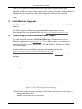
To check that Java is installed correctly and running, browse to:
http://www.java.com/en/download/help/testvm.xml
This page runs a test and displays a Java success (see Figure 15) or failure
message.
Figure 15: Java Test Page Success Message
If you do not see the success message, follow the instructions on the page to:
• Load and enable Java
• Enable Javascript in your browser
26
KRAMER: SIMPLE CREATIVE TECHNOLOGY
Controlling via the Embedded Web Pages
9.1
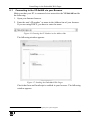
Connecting to the VP-8x4AK via your Browser
Make sure that your PC is connected via a network to the VP-8x4AK and do
the following:
1. Open your Internet browser.
2. Enter the unit’s IP number 1 or name in the Address bar of your browser.
If you are using DHCP, you have to enter the name.
Figure 16: Entering the IP Number in the Address Bar
The following window appears:
Figure 17: Loading the Embedded Web Pages
Check that Java and JavaScript is enabled in your browser. The following
window appears:
1 The default IP number is 192 168 1 39, and may be changed by the system integrator
27
Controlling via the Embedded Web Pages
Figure 18: First Time Security Warning
3. Click Run.
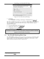
The VP-8x4AK switching control page is displayed (see Figure 19).
The Web embedded screens let you control the VP-8x4AK via the Ethernet.
The menu appears on the left side of the screen. There are three remote
operation Web pages:
• The switching matrix (see Section 9.2)
• Audio gain control (see Section 9.3)
• Configuration (see Section 9.4)
A help box is available for each screen when clicking the question mark that
appears on the left side of the screen.
9.2
The VP-8x4AK Switching Matrix Page
The VP-8x4AK switching matrix page lets you route any or all of the eight 1
inputs to any or all of the four outputs, by clicking the audio and/or video
signal indicators (purple and blue, respectively):
1 7 of the 8 inputs are shown in Figure 19
28
KRAMER: SIMPLE CREATIVE TECHNOLOGY
Controlling via the Embedded Web Pages
Figure 19: VP-8x4AK Embedded Web Page
You can perform the following operations via this Web page:
• Operate in the AFV mode or switch the audio and video separately, by
clicking the Audio, Video or AFV buttons (see Section 9.2.1)
• Deselect an audio and/or video signal 1 by clicking that signal indicator
• Operate in the At Once or Confirm mode (see Section 9.2.2)
• Lock or unlock the front panel, by clicking the lock icon
• Store and recall switching configurations (see Section 9.2.3)
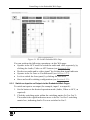
9.2.1 Switch an Input to an Output via the Embedded Web Pages
To switch an input to an output (for example, input 1 to output 4):
1. Set the button to the desired operation mode (Audio, Video or AFV, as
required).
2. Click the switching-point within the switching matrix (In 2 to Out 3).
The audio/video signal indicators move to the In 2 to Out 3 switching
matrix box, indicating that In 2 is now switched to Out 3.
1 Depending on the operation mode (Audio, Video or AFV)
29
Controlling via the Embedded Web Pages
Figure 20: Switching an Input to an Output
9.2.2 Operate in the Confirm Mode
By default, the device is set to the At-Once mode. To operate in the Confirm
mode:
1. Click the red Offline button.
2. Click the desired switching-point in the switching matrix.
Audio/video indicator outlines appear and the Take and Cancel buttons
turn blue.
Figure 21: Switching an Input to an Output in the Confirm Mode
3. Click either Take (to accept change) or Cancel.
You can repeat steps 2 and 3 several times.
To confirm several actions, select several switching points and then press TAKE
4. Click the Online button to exit the Confirm mode.
If you click the Online button before you click the TAKE button, the
following warning appears:
30
KRAMER: SIMPLE CREATIVE TECHNOLOGY
Controlling via the Embedded Web Pages
Figure 22: Exiting Offline Warning
9.2.3 Store and Recall Setups
To store a matrix configuration:
1. From the Preset drop-down list, select a preset (for example, Preset 03).
Presets that contain a configuration are displayed with a blue background;
presets with no configuration have a white background.
When selecting a preset, the Store button changes from gray to dark blue.
Figure 23: Selecting a preset
2. Click the Preview button to view the current setup stored in Preset 3.
3. Make sure the matrix is set to the desired configuration. If not, set it as
required.
4. Click Store.
The following window appears:
31
Controlling via the Embedded Web Pages
Figure 24: Save Preset Message
5. Click OK.
The new In/Out configuration is stored in Preset 03.
To recall a preset configuration:
1. Select the desired preset number from the Preset drop-down list 1 (for
example, Preset 08):
2. Click and hold the Preview button to view the selected Preset and then
release.
3. Click Recall.
The following window appears:
Figure 25: Load Preset Message
4. Click OK.
The new In/Out configuration takes effect.
You can recall a preset configuration in the Confirm mode by repeating the
above procedure in the Offline state. The recalled configuration will become
active when you press the Take button.
1 When selecting a preset that contains a configuration, the Recall button changes from gray to dark blue
32
KRAMER: SIMPLE CREATIVE TECHNOLOGY
Controlling via the Embedded Web Pages
Figure 26: Recalling a Preset in the Confirm Mode
The Help Box ?
This is the main panel window. In this window you can control the channels.
9.3
Audio Gain Page
The AUDIO GAIN screen lets you set the gain for each of the input and
output channels:
Figure 27: Audio Gain
To change an input or output gain, select the channel number, then click and
hold the + or – buttons to increase or decrease the gain, respectively.
A single click will increase/decrease the audio gain by 0.5 units; double click
to increase/decrease the gain by 1 unit.
The Help Box ?
In this page you can control the audio gain of the channels.
33
Controlling via the Embedded Web Pages
9.4
The Configurations Page
The CONFIGURATIONS page lets you view some Ethernet settings 1 and
change others (see Figure 28).
To change the configuration definitions:
1. Click CONFIGURATIONS.
The CONFIGURATIONS Web page appears.
2. Change the definitions as required.
3. Click the Submit button to apply changes 2. A window appears asking if
you are sure you want to change the network settings.
4. Click Yes.
A window appears announcing that the configuration has been
successfully changed.
5. Click OK
6. If the IP number had been changed, close the browser and reload the Web
page.
Figure 28: CONFIGURATIONS Embedded Web Page
HELP BOX ?
This page lets you view and set the device configuration.
1 The model name, serial number, firmware version and MAC address
2 Or Cancel to cancel changes
34
KRAMER: SIMPLE CREATIVE TECHNOLOGY
Technical Specifications
10 Technical Specifications
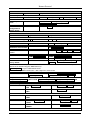
Table 4 lists the technical specifications:
1
Table 4: Technical Specifications of the VP-8x4AK 8x4 Video Audio Matrix Switcher
INPUTS:
OUTPUTS:
MAX. OUTPUT LEVEL:
BANDWIDTH (-3dB):
DIFF. GAIN:
DIFF. PHASE:
K-FACTOR:
S/N RATIO:
CROSSTALK (all hostile):
CONTROLS:
COUPLING:
AUDIO THD + NOISE:
AUDIO 2nd HARMONIC:
POWER SOURCE:
D MENSIONS:
WEIGHT:
ACCESSORIES:
OPTIONS:
8 XGA on 15-pin HD connectors (VGA through UXGA);
8 unbalanced stereo audio 3.5mm mini connectors
4 VGA on 15-pin HD connectors (VGA through UXGA);
4 balanced stereo audio terminal block connectors
VIDEO: 2.3Vpp
AUDIO: 3.2dBu
VIDEO: 360MHz
AUDIO: 22kHz
0.05%
0.05%
<0.05%
VIDEO: 66dB @5MHz
AUDIO: 82dB
VIDEO: -52dB, 5MHz
AUDIO: Bal: <-70dB @20kHz
Input/output selector buttons, all, off, video, audio, AFV, store, recall, take
audio level, and lock buttons. RS-232, RS-485, and Ethernet control. Input
and output level control, infrared
VIDEO: DC
AUDIO: AC
0.24%
0.002%
100-240V AC, 19VA
19" x 7" x 2U W, D, H
3.8kg (8.4lbs) approx
Power cord, rack “ears”, Windows®-based control software
2
External remote IR receiver cable
1 Specifications are subject to change without notice
2 P/N: C-A35M/IRR-50
35
Communication Parameters
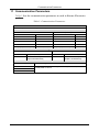
11 Communication Parameters
Table 5 lists the communication parameters as used in Kramer Electronics
products.
Table 5: Communication Parameters
EDID
EDID data is passed between Output 1 and Input 1
RS-232
Protocol 2000
Baud Rate:
Data Bits:
Stop Bits:
Parity:
Command Format:
Example (Output 1 to Input 1):
Protocol 3000 (Default)
Baud Rate:
Data Bits:
Stop Bits:
Parity:
Command Format:
Example (Output 1 to Input 1):
115,200
8
1
None
ASCII
#AV 1>1<CR>
Switching Protocol
P3000 -> P2000
P2000 -> P3000
Command:
0x38, 0x80, 0x83, 0x81
Command:
#P2000<CR>
Front Panel:
Press and hold Output 1 and
Output 3 simultaneously
Front Panel:
Press and hold Output 1 and
Output 2 simultaneously
Default Settings
IP Address: 192.168.1 39
TCP Port #: 5000
UDP Port #: 50000
36
9600
8
1
None
HEX
0x01, 0x81, 0x81, 0x81
Ethernet
Reset Settings
Power cycle the unit while holding in the Factory Reset button, located on
the rear panel of he unit.
KRAMER: SIMPLE CREATIVE TECHNOLOGY
Table of ASCII Codes for Serial Communication (Protocol 3000)
12 Table of ASCII Codes for Serial Communication (Protocol
3000)
Table 6 and Table 7 list the ASCII codes that switch an input to an output for a
single VP-8x4AK machine. For more detailed information, see Section 14.2.
Table 6: VP-8x4AK Video Signal Codes for Protocol 3000
OUT 1
OUT 2
OUT 3
OUT 4
IN 1 #V 1>1 CR #V 1>2 CR #V 1>3 CR #V 1>4 CR
IN 2 #V 2>1 CR #V 2>2 CR #V 2>3 CR #V 2>4 CR
IN 3 #V 3>1 CR #V 3>2 CR #V 3>3 CR #V 3>4 CR
IN 4 #V 4>1 CR #V 4>2 CR #V 4>3 CR #V 4>4 CR
IN 5 #V 5>1 CR #V 5>2 CR #V 5>3 CR #V 5>4 CR
IN 6 #V 6>1 CR #V 6>2 CR #V 6>3 CR #V 6>4 CR
IN 7 #V 7>1 CR #V 7>2 CR #V 7>3 CR #V 7>4 CR
IN 8 #V 8>1 CR #V 8>2 CR #V 8>3 CR #V 8>4 CR
Table 7: VP-8x4AK Audio Signal Codes for Protocol 3000
OUT 1
OUT 2
OUT 3
OUT 4
IN 1 #A 1>1 CR #A 1>2 CR #A 1>3 CR #A 1>4 CR
IN 2 #A 2>1 CR #A 2>2 CR #A 2>3 CR #A 2>4 CR
IN 3 #A 3>1 CR #A 3>2 CR #A 3>3 CR #A 3>4 CR
IN 4 #A 4>1 CR #A 4>2 CR #A 4>3 CR #A 4>4 CR
IN 5 #A 5>1 CR #A 5>2 CR #A 5>3 CR #A 5>4 CR
IN 6 #A 6>1 CR #A 6>2 CR #A 6>3 CR #A 6>4 CR
IN 7 #A 7>1 CR #A 7>2 CR #A 7>3 CR #A 7>4 CR
IN 8 #A 8>1 CR #A 8>2 CR #A 8>3 CR #A 8>4 CR
Table 8 lists the codes that set the audio input gain. For more detailed
information, see Section 14.2.
Table 8: VP-8x4AK Audio Input Gain Codes
INPUT 1
INPUT 5
INPUT X*
Level
[Rel]
#AUD-LVL 1,1, -100CR
#AUD-LVL 1,5, -100CR
#AUD-LVL 1,X, -100CR
-100dB Mute
#AUD-LVL 1,1, -50CR
#AUD-LVL 1,5, -50CR
#AUD-LVL 1,X, -50CR
-50dB
#AUD-LVL 1,1, 0CR
#AUD-LVL 1,5, 0CR
#AUD-LVL 1,X, 0CR
0dB
#AUD-LVL 1,1, 20CR
#AUD-LVL 1,5, 20CR
#AUD-LVL 1,X, 20CR
+20dB (Max)
* Where X is the input number from 1 - 8 For example, for channel 7 and relative level -50dB, #AUD-LVL 1,7, -50CR
Table 9 lists the codes that set the audio output gain. For more detailed
information, see Section 14.2.
37
Hex Codes for Serial Communication (Protocol 2000)
Table 9: VP-8x4AK Audio Output Gain Codes
Level
[Rel]
OUTPUT 1
OUTPUT 4
OUTPUT X*
#AUD-LVL 2,1, -100CR
#AUD-LVL 2,4, -100CR
#AUD-LVL 2,X, -100CR
-100dB Mute
#AUD-LVL 2,1, -50CR
#AUD-LVL 2,4, -50CR
#AUD-LVL 2,X, -50CR
-50dB
#AUD-LVL 2,1, 0CR
#AUD-LVL 2,4, 0CR
#AUD-LVL 2,X, 0CR
0dB
#AUD-LVL 2,1, 13CR
#AUD-LVL 2,4, 13CR
#AUD-LVL 2,X, 7CR
+7dB (Max)
* Where X is the output number from 1 - 8 For example, for channel 7 and relative level -50dB, #AUD-LVL 2,7, -50CR
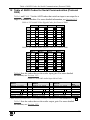
13 Hex Codes for Serial Communication (Protocol 2000)
The Hex codes listed in this section are used to set video channels for a single
machine (set as Machine 1) connected via either RS-232 or Ethernet. Similar
hex codes are used when the VP-8x4AK is connected via RS-485 and the
machine is set to number 2.
Table 10 lists the Hex codes that switch video channels:
Table 10: VP-8x4AK Hex Codes for Switching via RS-232/RS-485
Switching Video Channels
OUT 1
OUT 2
OUT 3
IN 1
IN 2
IN 3
IN 4
IN 5
IN 6
IN 7
IN 8
OUT 4
01 81 81 81 01 81 82 81 01 81 83 81 01 81 84 81
01 82 81 81 01 82 82 81 01 82 83 81 01 82 84 81
01 83 81 81 01 83 82 81 01 83 83 81 01 83 84 81
01 84 81 81 01 84 82 81 01 84 83 81 01 84 84 81
01 85 81 81 01 85 82 81 01 85 83 81 01 85 84 81
01 86 81 81 01 86 82 81 01 86 83 81 01 86 84 81
01 87 81 81 01 87 82 81 01 87 83 81 01 87 84 81
01 88 81 81 01 88 82 81 01 88 83 81 01 88 84 81
Table 11 lists the Hex codes that switch video channels:
Table 11: VP-8x4AK Hex Codes for Switching Audio Channels via RS-232/RS-485
Switching Audio Channels
OUT 1
OUT 2
OUT 3
IN 1
IN 2
IN 3
IN 4
IN 5
IN 6
IN 7
IN 8
38
OUT 4
02 81 81 81 02 81 82 81 02 81 83 81 02 81 84 81
02 82 81 81 02 82 82 81 02 82 83 81 02 82 84 81
02 83 81 81 02 83 82 81 02 83 83 81 02 83 84 81
02 84 81 81 02 84 82 81 02 84 83 81 02 84 84 81
02 85 81 81 02 85 82 81 02 85 83 81 02 85 84 81
02 86 81 81 02 86 82 81 02 86 83 81 02 86 84 81
02 87 81 81 02 87 82 81 02 87 83 81 02 87 84 81
02 88 81 81 02 88 82 81 02 88 83 81 02 88 84 81
KRAMER: SIMPLE CREATIVE TECHNOLOGY
Hex Codes for Serial Communication (Protocol 2000)
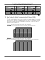
Table 12 lists the Hex codes that increase or decrease the audio input gain:
Table 12: VP-8x4AK Hex Codes for Increasing/Decreasing the Audio Input Gain
IN 1
IN 2
IN 3
IN 4
IN 5
IN 6
IN 7
IN 8
Increase
18 81 86 81
18 82 86 81
18 83 86 81
18 84 86 81
18 85 86 81
18 86 86 81
18 87 86 81
18 88 86 81
Decrease
18 81 87 81
18 82 87 81
18 83 87 81
18 84 87 81
18 85 87 81
18 86 87 81
18 87 87 81
18 88 87 81
Table 13 lists the Hex values that set the audio input gain:
Table 13: VP-8x4AK Hex Codes for Setting the Audio Input Gain
IN 1
IN 2
*
IN 3
*
IN 4
*
IN 5
*
IN 6
*
IN 7
*
Level
[Rel]
IN 8
*
*
16 81 80 81 16 82 80 81 16 83 80 81 16 84 80 81 16 85 80 81 16 86 80 81 16 87 80 81 16 88 80 81
Mute
16 81 87* 81 16 82 87* 81 16 83 87* 81 16 84 87* 81 16 85 87* 81 16 86 87* 81 16 87 87* 81 16 88 87* 81 -100dB Mute
*
*
*
*
*
*
*
*
-50dB
*
*
*
*
*
*
*
*
0dB
*
*
*
*
*
*
*
*
16 81 B9 81 16 82 B9 81 16 83 B9 81 16 84 B9 81 16 85 B9 81 16 86 B9 81 16 87 B9 81 16 88 B9 81
16 81 EB 81 16 82 EB 81 16 83 EB 81 16 84 EB 81 16 85 EB 81 16 86 EB 81 16 87 EB 81 16 88 EB 81
16 81 FF 81 16 82 FF 81 16 83 FF 81 16 84 FF 81 16 85 FF 81 16 86 FF 81 16 87 FF 81 16 88 FF 81 +20dB (Max)
* BYTE 3 = 0x80 + Gain Value (0x00-0x7F)
Table 14 lists the Hex codes that increase or decrease the audio output gain:
Table 14: VP-8x4AK Hex Codes for Increasing/Decreasing the Output Gain
OUT 1
OUT 2
OUT 3
OUT 4
Increase
18 81 80 81
18 82 80 81
18 83 80 81
18 84 80 81
Decrease
18 81 81 81
18 82 81 81
18 83 81 81
18 84 81 81
Table 15 lists the Hex codes that set the audio output gain.
Before sending the any of the codes in Table 15, the command 2A 87 80 81
must be sent.
Table 15: VP-8x4AK Hex Codes for Setting the Audio Output Gain
OUT 1
OUT 2
*
OUT 3
*
Level
[Rel]
OUT 4
*
*
16 81 80 81 16 82 80 81 16 83 80 81 16 84 80 81
Mute
16 81 94* 81 16 82 94* 81 16 83 8D* 81 16 84 94* 81 -100dB Mute
*
*
*
*
-50dB
*
*
*
*
0dB
*
*
*
*
16 81 C6 81 16 82 C6 81 16 83 C6 81 16 84 C6 81
16 81 F8 81 16 82 F8 81 16 83 F8 81 16 84 F8 81
16 81 FF 81 16 82 FF 81 16 83 FF 81 16 84 FF 81 +7dB (Max)
*BYTE 3 = 0x80 + Gain Value (0x00-0x7F)
39
Kramer Protocol
14 Kramer Protocol
By default, the VP-8x4AK is set to protocol 3000 (see Section 14.2) but is
also compatible with Kramer’s Protocol 2000 1 (see Section 14.3). Section
14.1 describes how to switch between protocol 3000 and protocol 2000.
14.1
Switching Protocols
You can switch protocols either via the front panel buttons (see Section
14.1.1) or the protocol commands (see Section 14.1.2).
14.1.1
Switching Protocols via the Front Panel Buttons
To switch from protocol 3000 to protocol 2000, press and hold 2 the OUT 1
and OUT 2 buttons for a few seconds.
The display shows 2000
To switch from protocol 2000 to protocol 3000, press and hold the OUT 1
and OUT 3 buttons for a few seconds.
The display shows 3000
14.1.2
Switching Protocols via Protocol Commands
To switch from protocol 3000 to protocol 2000, send the following command:
#P2000<CR>
To switch from protocol 2000 to protocol 3000, send the following command:
0x38, 0x80, 0x83, 0x81
3
The Windows®-based Kramer control software operates with protocol 2000. If
the VP-8x4AK is set to protocol 3000, it is automatically switched to protocol
2000.
14.2
Kramer Protocol 3000
This RS-232/RS-485 communication protocol lets you control the machine
from any standard terminal software (for example, Windows®
HyperTerminal Application) and uses a data rate of 115200 baud, with no
parity, 8 data bits, and 1 stop bit.
1 You can download our user-friendly “Software for Calculating Hex Codes for Protocol 2000” from the technical support
section on our Web site at: http://www kramerelectronics com
2 Not as part of a switching operation
3 Download the latest software from our Web site at http://www kramerelectronics com
40
KRAMER: SIMPLE CREATIVE TECHNOLOGY
Kramer Protocol
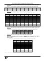
14.2.1
Protocol 3000 Syntax
Host message format:
Start Address (optional)
#
Destination_id@
Body
message
Delimiter
CR
Simple command (commands string with only one command without
addressing):
start
#
body
Command SP Parameter_1,Parameter_2,…
delimiter
CR
Commands string (formal syntax with commands concatenation and
addressing):
# Address@ Command_1 Parameter1_1,Parameter1_2,… |Command_2
Parameter2_1,Parameter2_2,… |Command_3
Parameter3_1,Parameter3_2,… |…CR
Device message format:
Start
Address (optional)
Body
~
Sender_id@
message
Delimiter
CR LF
Device long response (Echoing command):
Start
Address (optional)
Body
~
Sender_id@
command SP [param1 ,param2
Delimiter
…] result
CR LF
CR = Carriage return (ASCII 13 = 0x0D)
LF = Line feed (ASCII 10 = 0x0A)
SP = Space (ASCII 32 = 0x20)
41
Kramer Protocol
14.2.2
Command Parts Details
Command:
Sequence of ASCII letters ('A'-'Z', 'a'-'z' and '-')
Command will separate from parameters with at least single space
Parameters:
Sequence of Alfa-Numeric ASCII chars ('0'-'9','A'-'Z','a'-'z' and some special chars for specific commands), parameters will be
separated by commas
Message string:
Every command must to be entered as part of message string that begin with message starting char and end with message
closing char, note that string can contain more then one command separated by pipe ("|") char
Message starting char:
'#' for host command\query
'~' for machine response
Device address (Optional, for Knet):
Knet Device ID follow by '@' char
Query sign = '?', will follow after some commands to define query request
Message closing char =
Host messages - Carriage Return (ASCII 13), will be referred to by CR in this document
Machine messages - Carriage Return (ASCII 13) + Line-Feed (ASCII 10), will be referred to by CRLF
Spaces between parameters or command parts will be ignored
Commands chain separator char:
When message string contains more than one command, commands will be separated by pipe ("|")
Commands entering:
If terminal software used to connect over serial \ ethernet \ USB port, that possible to directly enter all commands characters
(CR will be entered by Enter key, that key send also LF, but this char will be ignored by commands parser)
Sending commands from some controllers (like Crestron) require coding some characters in special form (like \X##)
Anyway, there is a way to enter all ASCII characters, so it is possible to send all commands also from controller
(Similar way can use for URL \ Telnet support that maybe will be added in future)
Commands forms:
Some commands have short name syntax beside the full name to allow faster typing, response is always in long syntax
Commands chaining:
It is possible to enter multiple commands in same string by '|' char (pipe)
In this case the message starting char and the message closing char will be entered just one time, in the string beginning
and at the end
All the commands in string will not execute until the closing char will be entered
Separate response will be sent for every command in the chain
Input string max length:
64 characters
Backward support:
Design note: transparent supporting for protocol 2000 will be implemented by switch protocol command from protocol 3000
to protocol 2000, in protocol 2000 there is already such a command to switch protocol to ASCII protocol (#56 : H38 H80 H83
H81)
42
KRAMER: SIMPLE CREATIVE TECHNOLOGY
Kramer Protocol
Table 16: Instruction Codes for Protocol 3000
Help commands
Command
Protocol Handshaking
Syntax
#CR
Response
~OKCRLF
Device initiated messages
Command
Start message
Syntax
Kramer Electronics LTD. , Device Model
Version Software Version
Switcher actions
Audio-video channel has switched (AFV mode)
AV IN>OUT
Video channel has switched (Breakaway mode)
VID IN>OUT
Audio channel has switched (Breakaway mode)
AUD IN>OUT
Result codes (errors)
Syntax
COMMAND PARAMETERS OK
No error. Command running succeeded
Protocol Errors
Syntax Error
ERR001
Command not available for this device
ERR002
Parameter is out of range
ERR003
Unauthorized access (running command without the match login).
ERR004
Basic routing commands
Command
Syntax
Switch audio & video AV IN>OUT, IN>OUT, …
Response
AV IN>OUT, IN>OUT,…RESULT
Switch video only
VID IN>OUT, IN>OUT, …RESULT
VID IN>OUT, IN>OUT, …
Short form: V IN>OUT, IN>OUT, …
Note:
When AFV mode is active, this command will switch also audio. If audio is breakaway – device display mode will
change to show audio connections status.
Switch audio only
AUD IN>OUT, IN>OUT, …
Short form: A IN>OUT, IN>OUT, …
AUD IN>OUT, IN>OUT, …RESULT
Note: When AFV mode is ac ive, this command will switch also video.
Read video
connection
Read audio
connection
VID? OUT
Short form: V? OUT
VID? *
VID IN>OUT
AUD? OUT
Short form: A? OUT
AUD? *
AUD IN>OUT
VID IN>1, IN>2, …
AUD IN>1, IN>2, …
Parameters Descrip ion:
IN = Input number or '0' to disconnect output.
'>' = Connection character between in and out parameters.
OUT = Output number or '*' for all outputs.
43
Kramer Protocol
Examples:
Switch Video and Audio input 3 to output 7
#AV 3>7CR
~AV 3>7 OKCRLF
Switch Video input 2 to output 4
#V 2>4CR
~VID 2>4 OKCRLF
Switch Video input 4 to output 2 in machine #6@VID 4>2CR
number 6
~6@VID 4>2 OKCRLF
Disconnect Video and Audio Output 4
#AV 0>4CR
~AV 0>4 OKCRLF
Switch Video Input 3 to All Outputs
#V 3>*CR
~VID 3>* OKCRLF
Chaining Multiple
commands*
#AV 1>* | V 3>4, 2>2, 82>1, 0>2 |V 82>3| A 0>1 | V? * CR
First switch all Audio and video outputs from input 1,
Then switch video input 3 to output 4, video input 2 to output
2, video input and disconnect video output 2.
Then switch audio input 3 to output 2,
Then disconnect audio output 1.
Then get status of all links (assume this is 4x4 matrix).
Commands processing start after entering CR, response will sent
for each command after processing it.
~AV 1>* OKCRLF
~VID 1>2, 3>4
OKCRLF
~VID 82>3 ERR###
CRLF
~AUD 0>1 OKCRLF
~V 1>1, 0>2, 1>3,
3>4 CRLF
Signal Status commands
Command
Syntax
Change signal status
Response
SIGNAL INPUT, STATUS
Get signal status
SIGNAL INPUT, STATUS
-------------------
SIGNAL? INPUT
Parameters Description:
NPUT = Input number, ‘*’ for all.
STATUS = Signal state:
"0" or "off" for not existent signal.
"1" or "on" for existent signal.
Preset commands
Command
Store current
connections to preset
Syntax
PRST-STO PRESET
Short form: PSTO PRESET
Response
PRST-STO PRESET RESULT
Recall saved preset
PRST-RCL PRESET
Short form: PRCL PRESET
PRST-RCL PRESET RESULT
Delete saved preset
PRST-DEL PRESET
Short form: PDEL PRESET
PRST-DEL PRESET RESULT
Read video
connections from
saved preset
PRST-VID? PRESET OUT
Short form: PVID? PRESET OUT
PRST-VID? PRESET, *
PRST-VID PRESET, IN>OUT
Read audio
connections from
saved preset
PRST-AUD? PRESET OUT
Short form: PAUD? PRESET OUT
PRST-AUD? PRESET, *
PRST-AUD PRESET: IN>OUT
Read saved presets
list
PRST-LST?
Short form: PLST?
PRST-LST PRESET, PRESET, …
44
PRST-VID PRESET, IN>1, IN>2,…
PRST-AUD PRESET: IN>1, IN>2,…
KRAMER: SIMPLE CREATIVE TECHNOLOGY
Kramer Protocol
Preset commands
Command
Syntax
Response
Parameters Description:
PRESET = Preset number.
OUT = Output in preset to show for, '*' for all.
Examples:
Store current Audio & Video
connections to preset 5
#PRST-STR 5CR
~PRST-STR 5 OKCRLF
Recall Audio & Video
connections from preset 3
#PRCL 3CR
~PRST-RCL 3 OKCRLF
Show source of video output 2
from preset 3
#PRST-VID? 3,2CR
~PRST-VID 3: 4>2 CRLF
Syntax
LOCK-FP LOCK-MODE
Short form: LCK LOCK-MODE
Response
LOCK-FP LOCK-MODE RESULT
LOCK-FP?
LOCK-FP LOCK-MODE
Operation commands
Command
Lock front panel
Get front panel locking state
Parameters Description:
LOCK-MODE = Front panel locking state:
"0" or "off" to unlock front panel buttons.
"1" or "on" to lock front panel buttons.
Restart device
RESET
RESET OK
Switch to protocol 2000*
P2000 OK
P2000
* Protocol 2000 has command to switch back to ASCII protocol (like protocol 3000)
Audio parameters commands
Command
Syntax
Set audio level in specific AUD-LVL STAGE, CHANNEL, VOLUME
amplifier stage.
Short form: ADL STAGE, CHANNEL, VOLUME
Read audio volume level
AUD-LVL? STAGE, CHANNEL
Short form: ADL? STAGE
Response
AUD-LVL STAGE,
CHANNEL, VOLUME
RESULT
AUD-LVL STAGE,
CHANNEL, VOLUME
Parameters Description:
STAGE =
"In","Out"
or
Numeric value (present audio processing stage). For example: "0" for Input level, "1" for Pre-Amplifier, "2" for
Amplifier (Out) etc.
CHANNEL = Input or Output #
VOLUME = Audio parameter in Kramer units, precede minus sign for nega ive values.
++ increase current value,
-- decrease current value.
45
Kramer Protocol
Machine info commands
Command
Syntax
Response
* Time settings commands require admin authorization
Read in\outs count INFO-IO?
INFO-IO: IN INPUTS_COUNT, OUT OUTPUTS_COUNT
Read max presets
count
INFO-PRST?
INFO-PRST: VID PRESET_VIDEO_COUNT, AUD
PRESET_AUDIO_COUNT
Reset
configuration to
factory default
FACTORY
FACTORY RESULT
Identification commands
Command
Syntax
Response
Protocol Handshaking
#CR
~OK CRLF
Read device model
MODEL?
MODEL MACHINE_MODEL
Read device serial number SN?
SN SERIAL_NUMBER
VERSION?
VERSION MAJOR .MINOR .BUILD .REVISION
Set machine name
NAME MACHINE_NAME
NAME MACHINE_NAME RESULT
Read machine name
NAME?
NAME MACHINE_NAME
Reset machine name to
factory default*
NAME-RST
NAME-RST MACHINE_FACTORY_NAME
RESULT
Read device firmware
version
*Note: machine name not equal to model name. This name relevance for site viewer identifica ion of specific
machine or for network using (wi h DNS feature on).
MACHINE_NAME = Up to 14 Alfa-Numeric chars.
* Machine factory name = Model name + last 4 digits from serial number.
Set machine id number
MACH-NUM
MACHINE_NUMBER
MACH-NUM OLD_MACHINE_NUMBER
,NEW_MACHINE_NUMBER RESULT
* Response will send after machine number has been changed. So the replay with header will be:
NEW_MACHINE_NUMBER @MACH-NUM OLD_MACHINE_NUMBER NEW_MACHINE_NUMBER OK
Network settings commands
Set IP Address
NET-IP IP_ADDRESS
NTIP
NET-IP IP_ADDRESS RESULT
Read IP Address
NET-IP?
NTIP?
NET-IP IP_ADDRESS
Read MAC Address
NET-MAC?
NTMC
NET-MAC MAC_ADDRESS
Set subnet mask
NET-MASK SUBNET_MASK
NTMSK
NET-MASK SUBNET_MASK RESULT
Read subnet mask
NET-MASK?
NTMSK?
NET-MASK SUBNET_MASK
46
KRAMER: SIMPLE CREATIVE TECHNOLOGY
Kramer Protocol
Network settings commands
Set gateway address
NET-GATE GATEWAY_ADDRESS
NTGT
NET-GATE?
Read subnet mask
NTGT?
Set DHCP mode
Read subnet mask
NET-DHCP DHCP_MODE
NTDH
NET-DHCP?
NTDH?
NET-GATE GATEWAY_ADDRESS RESULT
NET-GATE GATEWAY_ADDRESS
NET-DHCP DHCP_MODE RESULT
NET-DHCP DHCP_MODE
DHCP_MODE =
0 – Don't use DHCP (Use IP set by factory or IP set command).
1 – Try to use DHCP, if unavailable use IP as above.
Change protocol
ethernet port
ETH-PORT PROTOCOL , PORT
ETHP
ETH-PORT PROTOCOL ,PORT RESULT
Read protocol
ethernet port
ETH-PORT? PROTOCOL
ETHP?
ETH-PORT PROTOCOL , PORT
PROTOCOL = TCP / UDP (transport layer protocol)
PORT = ethernet port to enter protocol 3000 commands.
1-65535 = User defined port
0 - reset port to factory default (50000 for UDP, 5000 for TCP)
Advanced switching commands
Command
Syntax
Set audio follow
AFV AFV-MODE
video mode
Note:
This command effect device front-panel mode and AUD\VID command.
Read audio follow AFV?
video mode
Response
AFV AFV-MODE RESULT
AFV AFV-MODE
AFV-MODE = Front panel AFV mode
"0" or "afv" to set front panel switching buttons in audio-follow-video state.
"1" or "brk" to set front panel switching buttons in their previous state when audio.
47
Kramer Protocol
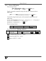
14.3
Kramer Protocol 2000
This RS-232/RS-485 communication protocol uses four bytes of information
as defined below. The default data rate is 9600 baud, with no parity, 8 data
bits and 1 stop bit.
Table 17: Protocol Definitions
MSB
0
7
LSB
DESTINATION
INSTRUCTION
D
6
N5
5
N4
4
N3
3
N2
2
N1
1
N0
0
I5
5
I4
4
I3
3
I2
2
I1
1
I0
0
O6
6
O5
5
O4
4
O3
3
O2
2
O1
1
O0
0
OVR
6
X
5
M4
4
M2
2
M1
1
M0
0
1st byte
INPUT
1
7
6
6
2nd byte
OUTPUT
1
7
3rd byte
MACHINE NUMBER
1
7
M3
3
4th byte
1st BYTE:
Bit 7 – Defined as 0
D – “DESTINATION”:
0 - for sending information to the switchers (from the PC);
1 - for sending to the PC (from the switcher)
N5
N0 – “INSTRUCTION”
The function that is to be performed by the switcher(s) is defined by the INSTRUCTION (6 bits) Similarly, if a function is
performed via the machine’s keyboard, then these bits are set with the INSTRUCTION NO , which was performed The
instruction codes are defined according to the table below (INSTRUCTION NO is the value to be set for N5 N0)
2nd BYTE:
Bit 7 – Defined as 1
I6
I0 – “INPUT”
When switching (ie instruction codes 1 and 2), the INPUT (7 bits) is set as the input number which is to be switched
Similarly, if switching is done via the machine’s front-panel, then these bits are set with the INPUT NUMBER which was
switched For other operations, these bits are defined according to the table
3rd BYTE:
Bit 7 – Defined as 1
O6
O0 – “OUTPUT”
When switching (ie instruction codes 1 and 2), the OUTPUT (7 bits) is set as the output number which is to be switched
Similarly, if switching is done via the machine’s front-panel, then these bits are set with the OUTPUT NUMBER which was
switched For other operations, these bits are defined according to the table
4th BYTE:
Bit 7 – Defined as 1
Bit 5 – Don’t care
OVR – Machine number override
M4
48
M0 – MACHINE NUMBER
KRAMER: SIMPLE CREATIVE TECHNOLOGY
Kramer Protocol
Used to address machines in a system via their machine numbers When several machines are controlled from a single serial
port, they are usually configured together with each machine having an individual machine number If the OVR bit is set, then
all machine numbers will accept (implement) the command, and the addressed machine will reply
For a single machine controlled via the serial port, always set M4
configured as MACHINE NUMBER = 1
M0 = 1, and make sure that the machine itself is
Table 18: Instruction Codes for Protocol 2000
Note: All values in the table are decimal, unless otherwise stated
INSTRUCTION
#
DESCRIPTION
DEFINITION FOR SPECIFIC INSTRUCTION
INPUT
OUTPUT
NOTE
0
1
RESET VIDEO
SWITCH V DEO
1
2
2
SWITCH AUDIO
3
STORE V DEO STATUS
0
Set equal to video input
which is to be switched
(0 = disconnect)
Set equal to audio input
which is to be switched
(0 = disconnect)
Set as SETUP #
4
5
RECALL VIDEO STATUS
REQUEST STATUS OF A
V DEO OUTPUT
REQUEST STATUS OF AN
AUDIO OUTPUT
BREAKAWAY SETTING
6
8
11
15
16
REQUEST BREAKAWAY
SETTING
REQUEST WHETHER SETUP
IS DEFINED / VAL D INPUT IS
DETECTED
ERROR / BUSY
Set as SETUP #
Set as SETUP #
Set as SETUP #
0
Set as SETUP #
SETUP #
or
Input #
For invalid / valid input
(i.e. OUTPUT byte = 4
or OUTPUT byte = 5),
this byte is set as the
input #
22
24
25
30
31
42
56
SET AUDIO PARAMETER
Equal to input / output
number whose parameter
is to be set
(0 = all)
INCREASE / DECREASE AUDIO Equal to input / output
PARAMETER
number whose parameter
is to be increased /
decreased
(0 = all)
REQUEST AUDIO PARAMETER Equal to input / output
number whose parameter
is requested
LOCK FRONT PANEL
0 - Panel unlocked
1 - Panel locked
REQUEST WHETHER PANEL
0
IS LOCKED
AUDIO PARAMETER
INPUT Bit:
SETTINGS FOR
I0 - 0=input; 1=output
NSTRUCTIONS 22, 24, 25
I1 - Left
I2 - Right
CHANGE TO ASCII
0
0
Set equal to video output which is
to be switched
(0 = to all the outputs)
Set equal to audio output which
is to be switched
(0 = to all the outputs)
0 - to store
1 - to delete
0
Equal to output number whose
status is reqd
Equal to output number whose
status is reqd
0 - audio-follow-video
1 - audio breakaway
0 - Request audio breakaway
setting
0 - for checking if setup is defined
1 - for checking if input is valid
0 - error
1 - invalid instruction
2 - out of range
3 - machine busy
4 - invalid input
5 - valid input
6 - RX buffer overflow
Set as parameter value
2
2, 3
2, 3
4, 3
4, 3
2
3, 4, 6
8
9, 25
2, 24
0 - increase output
1 - decrease output
2 - increase left output
3 - decrease left output
4 - increase right output
5 - decrease right output
6 - increase input
7 - decrease input
8 - increase left input
9 - decrease left input
10 -increase right input
11 - decrease right input
0
2
0
2
0
16
0 - Gain
1 - Bass
2 - Treble
3 - Midrange
4 - Mix On
Kramer protocol 3000
24
6, 24
19
49
Kramer Protocol
INSTRUCTION
#
DESCRIPTION
DEFINITION FOR SPECIFIC INSTRUCTION
INPUT
OUTPUT
NOTE
61
1 - video machine name
2 - audio machine name
3 - video software version
4 - audio software version
0 - Request first 4 digits
1 - Request first suffix
2 - Request second suffix
3 - Request third suffix
10 - Request first prefix
11 - Request second prefix
12 - Request third prefix
13
1 - number of inputs
2 - number of outputs
3 - number of setups
1 - for video
2 - for audio
14
62
IDENTIFY MACH NE
DEFINE MACHINE
NOTES on the above table:
NOTE 1 - When the master switcher is reset, (e g when it is turned on), the reset code is sent to the PC If this code is sent to
the switchers, it will reset according to the present power-down settings
NOTE 2 - These are bi-directional definitions That is, if the switcher receives the code, it will perform the instruction; and if
the instruction is performed (due to a keystroke operation on the front panel), then these codes are sent For example, if the
HEX code
01
85
88
83
was sent from the PC, then the switcher (machine 3) will switch input 5 to output 8 If the user switched input 1 to output 7
via the front panel keypad, then the switcher will send HEX codes:
41
81
87
83
to the PC
When the PC sends one of the commands in this group to the switcher, then, if the instruction is valid, the switcher replies by
sending to the PC the same four bytes that it was sent (except for the first byte, where the DESTINATION bit is set high)
NOTE 3 - SETUP # 0 is the present setting SETUP # 1 and higher are the settings saved in the switcher's memory, (i e those
used for Store and Recall)
NOTE 4 - The reply to a "REQUEST" instruction is as follows: the same instruction and INPUT codes as were sent are
returned, and the OUTPUT is assigned the value of the requested parameter The replies to instructions 10 and 11 are as per
the definitions in instructions 7 and 8 respectively For example, if the present status of machine number 5 is breakaway
setting, then the reply to the HEX code
0B
80
80
85
81
85
would be HEX codes
4B
80
NOTE 6 – If INPUT is set to 127 for these instructions, then, if the function is defined on this machine, it replies with
OUTPUT=1 If the function is not defined, then the machine replies with OUTPUT=0, or with an error (invalid instruction
code)
If the INPUT is set to 126 for these instructions, then, if possible, the machine will return the current setting of this function,
even for the case that the function is not defined For example, for a video switcher which always switches during the VIS of
input #1, (and its VIS setting cannot be programmed otherwise), the reply to the HEX code
0A
FE
80
81 (ie request VIS setting, with INPUT set as 126dec)
81
81 (ie VIS setting = 1, which is defined as VIS from input #1)
would be HEX codes
4A
FE
NOTE 8 - The reply is as in TYPE 3 above, except that here the OUTPUT is assigned with the value 0 if the setup is not
defined / no valid input is detected; or 1 if it is defined / valid input is detected
NOTE 9 - An error code is returned to the PC if an invalid instruction code was sent to the switcher, or if a parameter
associated with the instruction is out of range (e g trying to save to a setup greater than the highest one, or trying to switch an
input or output greater than the highest one defined) This code is also returned to the PC if an RS-232 instruction is sent
while the machine is being programmed via the front panel Reception of this code by the switcher is not valid
50
KRAMER: SIMPLE CREATIVE TECHNOLOGY
Kramer Protocol
NOTE 10 – This code is reserved for internal use
NOTE 13 - This is a request to identify the switcher/s in the system If the OUTPUT is set as 0, and the INPUT is set as 1, 2,
5 or 7, the machine will send its name The reply is the decimal value of the INPUT and OUTPUT For example, for a 2216,
the reply to the request to send the audio machine name would be (HEX codes):
7D
96
90
81 (i e 128dec+ 22dec for 2nd byte, and 128dec+ 16dec for 3rd byte)
If the request for identification is sent with the INPUT set as 3 or 4, the appropriate machine will send its software version
number Again, the reply would be the decimal value of the INPUT and OUTPUT - the INPUT representing the number in
front of the decimal point, and the OUTPUT representing the number after it For example, for version 3 5, the reply to the
request to send the version number would be (HEX codes):
7D
83
85
81 (i e 128dec+ 3dec for 2nd byte, 128dec+ 5dec for 3rd byte)
If the OUTPUT is set as 1, then the ASCII coding of the lettering following the machine’s name is sent For example, for the
VS-7588YC, the reply to the request to send the first suffix would be (HEX codes):
7D
D9
C3
81 (i e 128dec+ ASCII for “Y”; 128dec+ ASCII for “C”)
NOTE 14 - The number of inputs and outputs refers to the specific machine which is being addressed, not to the system For
example, if six 16X16 matrices are configured to make a 48X32 system (48 inputs, 32 outputs), the reply to the HEX code
3E
82
81
82 (ie request the number of outputs)
90
82
would be HEX codes
7E
82
ie 16 outputs
NOTE 16 - The reply to the “REQUEST WHETHER PANEL IS LOCKED” is as in NOTE 4 above, except that here the
OUTPUT is assigned with the value 0 if the panel is unlocked, or 1 if it is locked
NOTE 19 – After this instruction is sent, the unit will respond to the ASCII command set defined by the OUTPUT byte The
ASCII command to operate with the HEX command set must be sent in order to return to working with HEX codes
NOTE 24 – Further information needed in instructions 21, 22, 25 and 26, is sent using instruction 42 – which is sent prior to
the instruction For example, to request the audio gain value of right input # 9, send hex codes
2A
84
80
81
89
81
81
and then send HEX codes
19
To set MIX mode, send hex codes
2A
81
84
81
and then send HEX codes
16
NOTE 25 – For units which detect the validity of the video inputs, Instruction 16 will be sent whenever the unit detects a
change in the state of an input (in real-time)
For example, if input 3 is detected as invalid, the unit will send the HEX codes
10
83
84
81
If input 7 is detected as valid, then the unit will send HEX codes
10
87
85
81
51
LIMITED WARRANTY
Kramer Electronics (hereafter Kramer) warrants this product free from defects in material and workmanship under the
following terms
HOW LONG IS THE WARRANTY
Labor and parts are warranted for seven years from the date of the first customer purchase
WHO IS PROTECTED?
Only the first purchase customer may enforce this warranty
WHAT IS COVERED AND WHAT IS NOT COVERED
Except as below, this warranty covers all defects in material or workmanship in this product The following are not covered
by the warranty:
1 Any product which is not distributed by Kramer, or which is not purchased from an authorized Kramer dealer If you are
uncertain as to whether a dealer is authorized, please contact Kramer at one of the agents listed in the Web site
www kramerelectronics com
2 Any product, on which the serial number has been defaced, modified or removed, or on which the WARRANTY VOID
IF TAMPERED sticker has been torn, reattached, removed or otherwise interfered with
3 Damage, deterioration or malfunction resulting from:
i) Accident, misuse, abuse, neglect, fire, water, lightning or other acts of nature
ii) Product modification, or failure to follow instructions supplied with the product
iii) Repair or attempted repair by anyone not authorized by Kramer
iv) Any shipment of the product (claims must be presented to the carrier)
v) Removal or installation of the product
vi) Any other cause, which does not relate to a product defect
vii) Cartons, equipment enclosures, cables or accessories used in conjunction with the product
WHAT WE WILL PAY FOR AND WHAT WE WILL NOT PAY FOR
We will pay labor and material expenses for covered items We will not pay for the following:
1 Removal or installations charges
2 Costs of initial technical adjustments (set-up), including adjustment of user controls or programming These costs are the
responsibility of the Kramer dealer from whom the product was purchased
3 Shipping charges
HOW YOU CAN GET WARRANTY SERVICE
1
2
3
To obtain service on you product, you must take or ship it prepaid to any authorized Kramer service center
Whenever warranty service is required, the original dated invoice (or a copy) must be presented as proof of warranty
coverage, and should be included in any shipment of the product Please also include in any mailing a contact name,
company, address, and a description of the problem(s)
For the name of the nearest Kramer authorized service center, consult your authorized dealer
LIMITATION OF IMPLIED WARRANTIES
All implied warranties, including warranties of merchantability and fitness for a particular purpose, are limited in duration to
the length of this warranty
EXCLUSION OF DAMAGES
The liability of Kramer for any effective products is limited to the repair or replacement of the product at our option Kramer shall
not be liable for:
1 Damage to other property caused by defects in this product, damages based upon inconvenience, loss of use of the product, loss
of time, commercial loss; or:
2 Any other damages, whether incidental, consequential or otherwise Some countries may not allow limitations on how long an
implied warranty lasts and/or do not allow the exclusion or limitation of incidental or consequential damages, so the above
limitations and exclusions may not apply to you
This warranty gives you specific legal rights, and you may also have other rights, which vary from place to place
NOTE: All products returned to Kramer for service must have prior approval This may be obtained from your dealer
This equipment has been tested to determine compliance with the requirements of:
EN-50081:
EN-50082:
CFR-47:
"Electromagnetic compatibility (EMC);
generic emission standard
Part 1: Residential, commercial and light industry"
"Electromagnetic compatibility (EMC) generic immunity standard
Part 1: Residential, commercial and light industry environment"
FCC* Rules and Regulations:
Part 15: “Radio frequency devices
Subpart B Unintentional radiators”
CAUTION!
Servicing the machines can only be done by an authorized Kramer technician Any user who makes changes or
modifications to the unit without the expressed approval of the manufacturer will void user authority to operate the
equipment
Use the supplied DC power supply to feed power to the machine
Please use recommended interconnection cables to connect the machine to other components
* FCC and CE approved using STP cable (for twisted pair products)
52
KRAMER: SIMPLE CREATIVE TECHNOLOGY
For the latest information on our products and a list of Kramer
distributors, visit our Web site: www.kramerelectronics.com,
where updates to this user manual may be found.
We welcome your questions, comments and feedback.
Safety Warning:
Disconnect the unit from the power supply before
opening/servicing.
Caution
Kramer Electronics, Ltd.
Web site: www kramerelectronics.com
E-mail: [email protected]
P/N: 2900-000650 REV 2