Transcript
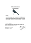
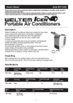
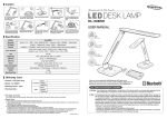
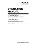
▣ Communication mode
▣ Specifications
A
N
Current consumption
U
A
SW input
(SW1, SW2)
L
NPN Solid-state input
PNP Solid-state input
BFC-N
BFC-P
Model
Power supply
BFC SERIES
M
Type
(※1)
Indication
●
●
Environment
Parameter: Red 4digit 7segment
Setting value: Green 4 digit 7 segment
Indicator: TX indicator(Red), RX indicator(Green)
Real-time monitoring (incident light level, on/off state)
Executes every BF5 feature and sets parameter by external device (Master)
●
●
Ambient
temperature
Ambient
humidity
Warning Serious injury may result if instructions are not followed.
Caution Product may be damaged, or injury may result if instructions are not followed.
※The following is an explanation of the symbols used in the operation manual.
Caution: Injury or danger may occur under special conditions.
PBT, PC
Connector cable(ø4, 4P, 2m, AWG 22, Insulator diameter: ø1.25), side connector
Unit weight
Approx. 15g
1) Serial communication
①Connect the USB to Serial converter(SCM-US, sold separately) to the PC loader port for communicating with PC.
②It is very easy to manage parameters and monitor data of connected amplifier units(BF5 Series) using
the integrated management program DAQMaster(free).(Refer to DAQMaster and amplifier unit manuals)
2) RS485 communication
● PLC connection
①Connect directly to a PLC using RS485 communication cable of the communication converter unit.
②Amplifier units(BF5 Series) can be controlled through PLC. (Refer to communication converter unit(BFC)
communication manual)
※ 1: Powered by supply voltage of the amplifier unit connected by a side connector.
※ Environment resistance is rated at no freezing or condensation.
PC connection
①Connect PC using Communication converter(SCM-38I or SCM-US48I, sold separately). (Refer to
Communication converter SCM series manual)
②Same as "1)Serial Communication information line ②".
1. In case of using this unit with machinery(Nuclear power control, medical equipment,
vehicle, train, airplane, combustion apparatus, entertainment or safety device etc.), it is
required to install fail-safe device, or contact us for information required.
It may cause a fire, human injury or property loss.
2. Do not disassemble or modify this unit. Please contact us when required.
It may give an electric shock and cause a fire.
▣ Proper usage
Before using this communication converter unit,depending on the usage environment,keep
following items handy.
Visit our web site(www.autonics.com) to download.
1) DAQMaster program(Integrated device management program), User Manual
2) SCM-US Driver(USB driver, Serial port driver), Manual
3) SCM-US48I Driver(USB driver, Serial port driver), Manual
4) SCM-38I Manual
4) Communication converter unit BFC User Manual For Communication
(Unit: mm)
Accessories
<Connector cable>
●
ø4.1
13.5
3
<Side connector>
4.7
17.5
Standard
EIA RS485
Maximum connections
31(Address setting: 01~99)
Communication method
2-wire half duplex
Synchronization method
Asynchronous
Effective communication distance
Max. 800m
1200, 2400, 4800, 9600,
Communication speed
19200, 38400bps
Standard
EIA RS485
Response wating time
20 ~ 99ms
Start bit
1bit(Fixed)
Stop bit
1bit, 2bit
Parity bit
None, Even, Odd
Data bit
8bit(Fixed)
Protocol
Modbus RTU
※ It is not allowed to set overlapping communication address at the same communication line.
※ Please use a proper twist pair for RS485 communication.
▣ Parameter setting
Communication standby mode
key 3 sec.
key 3 sec.
COM PARA
※After flashes twice, moves to communication mode setting.
①Config
Indicates the number of amplifier units connected to the communication
converter unit(BFC).
1TX(Send)-Red LED, RX(Receive)-Green LED: Turns on when communicates and inputs SW.
2Parameter indication(4digit Red 7segment): Indicates parameter and processes of communication
instruction/execution.
3Setting value indication(4digit Green 7segment): Indicates setting value and process of
communication instruction/execution.
4UP, DOWN key: To modify setting value.
5MODE key: To shift or select parameter when entering parameter setting mode.
6PC loader port: In case of PC communication, use USB to Serial converter(SCM-US, sold separately).
7Side cover: To connect an amplifier unit, use a side connector(accessory). Remove the side cover to
connect the amplifier unit.
8Connector cable port: The terminal for attaching a connector cable(accessory) is used for RS485
communication or SW input.
①
②
③
④
⑤
Communication mode
COM
②Status
Indicates the information of the selected amplifier unit(Dual, Single) by
channel, connected to communication converter unit(BFC).
<RS485>
(Orange)
▣ Installations
1. DIN rail installations
1)Attachment<Picture 1>
1Hang up the backside holder of the communication converter unit on DIN rail.
2Press the front part of the communication converter unit toward DIN rail.
ADR
③Program group
Setting values of the amplifier unit can be changed. When setting
values of the amplifier unit changed, TX(Red) and RX(Green) LEDs
on communication converter unit will flash indicating application of
setting values to the amplifier unit.
Serial
Com
B(Pink)
<SW input>
(Black)
I2C
Amplifier unit executing
instructions
(※2)Response waiting time
RWT
1Remove the side cover at the side of communication
converter unit where amplifier unit will be connected.
2Attach the side connector to the socket on the side of the
communication converter.
3After attaching the communication converter unit and
the amplifier unit to the DIN rail, push gently to have
both units fastened into each other.
※Improper connection may cause malfunction.
※Do not supply the power while connecting or disconnecting.
Stop bit
STOP 2BIT
ADR
key
※ 1:
2
BPS 192K
key
RWT
key
key
ADR
99
key
BPS 4800
21
key
RWT
99
PRTY EVEN
key
PRTY
ODD
key
key
※
: Factory default
STOP 1BIT
Communication
speed display
Speed
1200
Display
1200
2400
2400
4800
4800
9600
9600
19200
192K
38400
384K
※ 2: Communication response
waiting time range is 20
to 99ms.(Depending on
the number of amplifier
units connected, response
time may increase up to
350ms.)
key
▣ Troubleshooting
Error Code
ERA
ERB
Description
Solution
·Reading/Writing errors occur while processing data in ·Check the circuitry around EEPROM inside the
EEPROM of amplifier unit.
product.
·Slave fails to execute Master's group instructions such as ·Check the connection status between
Copy/Load/Save/Teaching sent through communication communication unit and amplifier units.
line due to unstable communication line.
·Check the circuitry around the side
·Other communication problems.
connector and hardware condition.
Solution methods for communication problems
Amplifier unit
(BF5 Series)
Bank Copy
Communication
converter unit
(BFC Series)
Picture 3
Bank Load All
0.5 sec. twice flash
Picture 4
Bank Save All
0.5 sec. twice flash
Teaching All
1) Communication errors during Serial or RS485 connections.
ⓐCheck if the communication mode selected in communication converter unit suits installation environment.
ⓑCheck and equalize the address of communication converter unit and address set in DAQMaster.
ⓒCheck and equalize the communication port of communication converter unit and the communication port
number set in DAQMaster.
2) Communication errors during SW signal input
ⓐCheck if the communication mode set in communication converter unit is SW input mode(SW Bank).
ⓑCheck if the connections are made thoroughly depending on NPN or PNP input type.
▣ Caution for using
1. In case power in supplied from a switching power supply, ensure that the frame ground(F.G.) terminal of the
power supply is connected to an actual ground and connect a condenser between 0V and F.G. terminal for
noise removal.
2. Avoid using the unit where dust exists or corrosion causing environments. It may cause product malfunction.
3. Do not start operating during initial power supplying time(3 sec.).
4. In case moving the unit from cold outside to a indoor room, start operating after removing moisture.
5. Do not wire high voltage / power source line and unit together. It may cause product damage or malfunction due to noise.
6. Do not use the unit outdoor or anywhere exposed to direct extraneous light. In case of max. sensitivity setting, there
might exist slight sensing distance difference due to each feature deviation.
7. Please note that this unit is non-isolated.
8. Installation environment
1)It shall be used indoor.
2)Altitude Max. 2,000m
3)Pollution Degree 3
4)Installation Category II
※ It may cause malfunction if above instructions are not followed.
▣ Major products
Vcc
(External)
(Black)
<SW Input>
※ The above specifications are subject to change without notice.
USB
key
Communication converter unit after
amplifier unit executes instructions
(White)
GND
(External)
20
PRTY NONE
Picture 2
COM
Serial communication mode
key
Parity bit
Initialize
(White)
key
key
2. Communication converter unit(BFC Series) and Amplifier unit(BF5 Series) Connection
4. USB to Serial converter(SCM-US) attachment and detachment
Connect the USB to Serial converter, SCM-US(sold separately), to PC loader port.
(Pink)
1
BPS 9600
Picture 1
Communication converter
unit recived an instruction
from DAQMaster
key
key
(※1)Communication speed
Communication waiting state
(Orange)
B-
SW BANK
SW input mode
key
④Data Bank Group
Data bank and group teaching features of amplifier unit can be set. Amplifier unit can be initialized as well.
※ Indications appear on communication converter and amplifier units depending on applied instruction are
shown below.
Bank Load
2)Detachment<Picture 2>
1Slide the back part of the communication converter unit as shown in figure ①.
2Lift up the communication converter unit as shown in figure ②.
<RS485>
A+
Main circuit
A+
key
key
Communication address
This indicates the waiting state for instructions while preserving master unit(PC,PLC) and communication converter unit real
time data transfer(incident light level of the amplifier unit).
2)Detachment<Picture 4>
Pull out the connector cable with pressing the connector
cable lever downside.
BFC-P
485
RS485 communication mode
key
1)Attachment<Picture 3>
Insert the connector cable into the installed communication
converter unit on DIN rail until it clicks.
BFC-N
WAIT ----
Communication parameter
※Following is a screen of DAQMaster properties window of a computer connected communication converter unit.
3. Connector cable attachment and detachment
▣ Connections
Main circuit
< Communication Specification >
Bank Save
▣ Dimensions
I2C
SW1: H
SW2: H
(NPN type)
●
1. This unit shall not be used outdoors.
It might shorten the life cycle of the product or give an electric shock.
Use this product indoors only. Do not use the product outdoors or at locations subject to the
temperature or humidity of outdoors.(Example: rain, dirty, frost, sunlight, condensation, etc.)
2. Do not use this unit where inflammable or explosive gas exists.
It may cause a fire or explosion.
3. Please observe the rated specifications.
It may damage or shorten the life cycle of the product.
4. Do not use this unit beyond rated power and do not supply AC power to a DC power type product.
It may cause a damage to the product.
5. Please check the polarity of power and wrong wiring.
It may cause a damage to the product.
6. Do not use this unit where there is vibration or a chance of impact.
It may cause a damage to the product.
7. When cleaning the unit, do not use water or an oil-based detergent.
It may cause a fire, give an electric shock or damage to the product.
Communication converter unit after
amplifier unit executes instructions
SW1: H
SW2: L
Caution: Do not connect a powered BF5 connector cable to a communication converter
unit(BFC). (It may cause damage the product.)
▣ Parts description
Caution
Amplifier unit executing
instructions
SW1: L
SW2: H
3) SW input
Warning
Serial
Com
Vcc
(PNP type)
(White)
Communication converter unit
BFC Series
IP40( IEC standards )
Material
Approval
At the standby state as shown above display indicates the current bank in use.
Communication converter unit received
SW input signal
(Black)
500m/s2(50G) X, Y, Z directions for 3 times
Accessory
(Pink) B-
SW input standby state
35 to 85%RH, Storage: 35 to 85%RH
Protection
※Please keep these instructions and review them before using this unit.
SCM-US48I
SCM-38I
Caution
Connector
cable
1.5mm amplitude at frequency of 10 to 55Hz(for 1 min.)
in each of X, Y, Z directions for 2 hours
Shock
※Please observe the cautions that follow;
Amplifier unit
BF5 Series
-10 to 50℃, Storage: -20 to 60℃
Vibration
▣ Caution for your safety
(Orange)A+
1200, 2400, 4800, 9600, 19200, 38400bps
●
3)SW input
[Chart1] Bank selection table based on SW input
SW input is a feature which allows amplifier unit
NPN
PNP
Bank
connected with the communication converter unit
SW1 SW2 SW1 SW2
to load all banks. Applying signals to SW1(Black) 1 Standby signal(Using set Bank) H
H
L
L
and SW2(White) of the connector cables which is
2
Bank 0
H
L
L
H
connected to the communication converter unit
Bank 1
L
H
H
L
allows change of banks as shown in chart 1.(SW 3
Bank 2
L
L
H
H
input signal duration should be longer than 3 4
seconds.)
※ Indications appear on communication converter and amplifier units depending on applied instruction are
shown below.
RS485 Communication, Serial Communication, SW input
Communication speed
Thank you very much for selecting Autonics products.
For your safety, please read the following before using.
2) RS485
Max. 40mA
LOW: 0-1V, HIGH: 5-24V
SW1/SW2 - HH: Standby, HL: BANK0,
SW1/SW2 - LL: Standby, LH: BANK0,
LH: BANK1, LL: BANK2
HL: BANK1, HH: BANK2
Communication function
Function
1) Serial communication
12-24VDC ±10%
SCM-US
Digital Fiber Optic Amplifier Communication Converter
This communication converter unit supports 2 communication modes and SW input mode. You can use only 1 mode of
3 modes.
SCM-US
⑤Data Bank
Setting value of data bank(Bank 0, Bank 1, Bank 2) can be saved.
■
■
■
■
■
■
■
■
■
■
■
■
■
Proximity sensors
■ Counters
Area sensors
■ Timers
Photoelectric sensors
■ Display units
Fiber optic sensors
■ Panel meters
Door/Door side sensors
■ Pressure sensors
Sensor controllers
■ Rotary encoders
Graphic/Logic panels
■ Power controllers
Temperature controllers
■ Tachometer/Pulse(Rate) meters
Temperature/Humidity transducers ■ Switching power supplies
Stepping motors/drivers/motion controllers
Field network devices
Laser marking system(CO₂, Nd:YAG)
Laser welding/soldering system
http://www.autonics.com
Satisfiable Partner For Factory Automation
■HEAD QUARTERS :
41-5. Yongdang-dong, Yangsan-si, Gyeongnam, 626-847,
Korea
■OVERSEAS SALES :
Bldg. 402 3rd FL., Bucheon Techno Park, 193, Yakdae-dong,
Wonmi-gu, Bucheon-si, Gyeonggi-do, 420-734, Korea
TEL : 82-32-610-2730 / FAX : 82-32-329-0728
■E-mail : [email protected]
The proposal of a product improvement
and development :[email protected]
EP-KE-77-0022