1
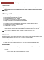
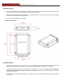
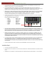
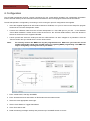
Installation & Quick Start Guide AIT1000 Class B AIS Transponder QUICK START AIT1000 - VR1.01 DIGITAL YACHT LTD AIT1000 Quick Start Guide 1. Introduction Congratulations on the purchase of your AIT1000 Class B AIS Transponder. It is recommended that your transponder is installed by a professional installer. Before operating the unit you should familiarise yourself with the complete user manual supplied with the product. 2. Before you start You will need the following items and tools to complete the installation: Class B AIS Transponder. Dedicated VHF/AIS antenna and cable – not supplied Dedicated GPS antenna and cable - supplied Access to 12V DC power supply where the unit is to be installed. Four M4 screws or other fixings appropriate to the mounting location. Transponder power and data cable - supplied To configure the unit you will need: ® ® Access to a PC running Microsoft Windows XP / Windows Vista / Windows 7 with a free USB port. proAIS Class B AIS Transponder configuration software. An MMSI number for your vessel Note: You can obtain an MMSI (Maritime Mobile Service Identity) from the same authority that issues ship radio licences in your area. An MMSI may have already been provided with your existing VHF radio licence. The MMSI number used for the AIS Transponder should be the same as that programmed into your VHF DSC radio. If you do not have an MMSI number the AIS Transponder will operate in receive only mode. Do not enter an invalid MMSI number. 3. Installation Before starting installation select a suitable location for the AIS Class B Transponder. The unit is water resistant; however it should be installed below deck in a dry location. When locating the unit you should consider: Routing of power and antenna cables to the unit. Provision of sufficient space behind the unit for cable connections. Routing of data connections to PC or chart plotter from the unit. Maintaining the compass safe distance of 0.5m. Visibility of the front panel indicators and access to the „Silent mode‟ or „Safety Related Message‟ button. Installation Step 1 Install VHF and GPS antenna according to the hand book instructions and following guidance and warnings in the main user manual for the AIS Class B Transponder. Run VHF and GPS antenna co-axial cables to the AIS Class B Transponder and terminate with the correct connectors: The VHF antenna cable should be terminated in a BNC connector The GPS antenna cable should be terminated in a TNC connector DIGITAL YACHT LTD AIT1000 Quick Start Guide Installation Step 2 Access to the fixing holes is achieved by removal of the two green decal strips down each side of the AIT1000. Once fixed in place, the green decal strips can be clicked back in place. Secure the AIS Transponder to a flat surface in the selected location. Use four M4 wood screws or other fixings suited to the material the unit is being fixed to. The unit may be installed in any orientation Fixing location drawing Installation Step 3 Provide power connections to the unit. Power is connected to the eight core PWR/DATA cable on the Red and Black wires. The Red wire is the positive (+) connection. The Black wire is the negative (-) connection. Connect the stripped wires to the nearest source of primary 12V DC power. Ensure that the supply is connected via the supplied 3A fuse or suitable circuit breaker. Add the fuse in the positive power connection to the unit if necessary. The AIS Class B Transponder is designed for a 12V DC system. A converter should be used if the vessel uses a 24V system. DIGITAL YACHT LTD AIT1000 Quick Start Guide The AIT1000 can be connected to other AIS compatible equipment via the NMEA0183 connections on the PWR/DATA cable and/or to a PC via the USB interface. The AIT1000 USB interface is designed to use the standard Serial Adaptor drivers that are supplied with Windows, but in case the “Found New Hardware Wizard” cannot locate the right drivers, they are included on the supplied CD-Rom. Simply plug the USB connector from the AIT1000 in to a spare USB port on the PC. When you turn on the AIT1000 for the first time, Windows should detect the new hardware and install the drivers automatically. It will allocate a COM Port number to the adaptor (COM1, COM2, COM3, etc.) and it is this COM Port number that you have to tell the PC Navigation software, that the AIS is connected on – consult the instruction manual supplied with your PC Software to understand how this is configured. A table showing what each of the 8 wires of the PWR/DATA cable does is printed on the AIT1000 Transponder and repeated below for your convenience; AIT1000 Transponder PWR/DATA cable o RED Power + (12v) o BLACK Power – (0v) o ORANGE NMEA Out + o BROWN NMEA Out – o YELLOW NMEA In + o GREEN NMEA In – o WHITE Remote SW + o BLUE Remote SW - The most common connection to a dedicated chart plotter is to take the NMEA Output (Orange+ and Brown –) from the AIT1000 Transponder and to connect it to a free NMEA Input on the plotter. You must then tell the chart plotter that AIS data is connected to this port and set the baud rate to 38,400 Baud – the standard speed for AIS data. Consult the instruction manual supplied with your Chart Plotter to understand how this is configured. NMEA 0183 heading data from an autopilot or fluxgate compass can be connected to The NMEA input of the AIT1000 and this data is then multiplexed with the AIS data and output on the NMEA Output at 38,400 baud – useful when connecting to equipment that only has one NMEA input and needs both heading and AIS data. All NMEA messages with a valid checksum are passed through the AIT1000 and re-transmitted along withe AIS data on the NMEA and USB connections. To connect a remote “Silence” switch that allows you to turn on/off the transmission of your own vessels position (good etiquette when moored or in congested but safe conditions), you will need a push button switch or conventional toggle type switch, connected between the White and Blue wires. This can be mounted anywhere on the boat and once configured using the supplied proAIS software, allows you to switch on/off the “Silent” mode of the AIT1000. Connect the GPS antenna (TNC connector) and VHF/AIS (BNC connector) to the AIT1000 Installation Step 4 Turn on the 12V power to the AIT1000 Verify that all four LED indicators on the front of the unit flash twice, followed by illumination of the amber and red LED‟s. Installation is now complete. The AIT1000 needs to be configured using the proAIS software – see next section. DIGITAL YACHT LTD AIT1000 Quick Start Guide 4. Configuration The AIT1000 transponder must be correctly configured for your vessel before operation. All configuration information must be entered carefully as this information will be transmitted to other AIS equipped vessels and shore stations. The AIS transponder is configured by connecting to a PC running the „proAIS‟ configuration tool supplied. Insert the supplied Digital Yacht AIS Product Resource CD-ROM, in to your PC and run the Setup.Exe program located in the “AIT1000 Transponder” folder. Connect the USB data cable from the AIT1000 transponder to a free USB port on your PC – if the Windows “Found New Hardware” wizard cannot locate the drivers for the AIT1000 USB interface, direct the Wizard to search for the drivers on the supplied CD-ROM. Launch proAIS and select the COM port that the USB interface has been mapped to by Windows. Click the „Connect‟ button and you should see the screen shown below. *Note: For security reasons the MMSI can only be programmed once. Make sure you enter the correct number and double check when proAIS warns you regarding MMSI programming. The MMSI can only be changed by returning the unit to your dealer. 1. Enter Vessel Name, Call Sign and MMSI 2. Enter vessel dimensions and location of GPS antenna to the nearest metre. 3. Select the most appropriate vessel type. 4. Select “Press Switch to Toggle Silent Mode” 5. Click “Save data to AIS” 6. Read the warning message carefully and proceed only if the MMSI number is correct. DIGITAL YACHT LTD AIT1000 Quick Start Guide 7. Configuration of the AIS Class B Transponder is now complete Please refer to the proAIS user guide in the AIT1000 User Manual for more detailed usage instruction. 5. Operation Once installed and configured correct operation of the AIS transponder should be verified as follows: 1. Check that at least one of the LED's on the front of the unit is illuminated. If the red 'Error' LED is illuminated please refer to the troubleshooting section below. 2. Check that the unit has a good GPS lock. If the GPS is locked the Latitude and Longitude will be displayed on the GPS tab in proAIS along with a number of green bars in the signal strength graph. 3. If the unit does not have GPS fix within a few minutes check your GPS antenna has a clear view of the sky, is to the correct specification and that the GPS antenna cable is connected. 4. Check that the Green 'Power' LED on the front of the unit illuminates. This will not happen until the unit has GPS fix and has transmitted its first position report. Please allow up to 5 minutes for this to occur. If the Green LED is illuminated you have successfully installed and configured the unit. The proAIS application can be closed and the PC disconnected from the unit. The unit requires only a power supply to operate. 5. If you are in an area with other AIS equipped vessels you can check the "Other vessels" tab in proAIS to view position reports received from other ships. If you contact another vessel to check your transmission please make sure the vessel is equipped to receive Class B messages. If not the vessel may see just your MMSI and position. 6. Troubleshooting If the green LED is not illuminated after around 5 minutes then please check the following: 1. Is the MMSI number programmed? Check the diagnostics tab in proAIS. If there is a red cross next to the "Transponder MMSI Valid" item then you have not correctly configured the MMSI. 2. Does the unit have a GPS position fix? Check the diagnostics tab in proAIS. If there is a red cross next to the "GPS position fix" item then the unit does not have GPS fix. Check your GPS antenna and connections. 3. Is the unit reporting any alarms? Check the "Active alarms" area in the diagnostics tab of proAIS & refer to the troubleshooting guide at the back of the proAIS user guide.