1
TVIP52501
User Manual
Version 02/2011
Original English user manual. Keep for future use.
59
English
Introduction
Dear Customer,
Thank you for purchasing this product.
This product meets the requirements of the applicable European and national guidelines. The
corresponding declarations and documents can be obtained from the manufacturer
(www.abus-sc.com).
To maintain this condition and to ensure risk-free operation, you as the user must observe these operation
instructions!
Before initial start-up, read through the complete operating instructions observing operating and safety
instructions.
All company and product names mentioned in this document are registered trademarks.
All rights reserved.
If you have any questions, please contact your installer or your local dealer!
Disclaimer
This user manual was prepared with greatest care. If you should notice omissions or inaccuracies, please
inform us about these on the back of this manual given address.
The ABUS Security-Center GmbH assumes no liability for technical and typographical faults and reserves
the right to make at any time modifications to the product or user manual without a previous announcement.
The company is not liable or responsible for direct and indirect subsequent damages which are caused in
connection with the equipment, the performance and the use of this product.
No guarantee for the content of this document is taken.
60
English
Icon explanation
A flash in the triangle is used if there is danger for the health, e.g. by an electric shock.
An exclamation mark in the triangle points to an important note in this user manual
which must be minded.
This symbol can be found when you are to be given tips and information on operation.
Important safety advice
The warranty will expire for damage due to non-compliance with these operating
instructions. ABUS will not be liable for any consequential loss!
ABUS will not accept liability for damage to property or personal injury caused by
incorrect handling or non-compliance with the safety-instructions.
In such cases the warranty will expire.
Dear customer,
The following safety instructions are intended not only for the protection of your health, but also for
the protection of the device. Please read through the following points carefully:
x
x
x
x
There are no parts on the inside of the product which need to be serviced. Apart from this, the license
(CE) and the guarantee/warranty will lapse if you open/take the product apart.
The product will be damaged even it falls from a low height.
This device can be used in internal area.
At the installation of the product please take care that direct sunlight cannot fall onto the image sensor
of the device. Please follow the installation instructions in the corresponding chapter of this user
manual.
Avoid using the device under the following unfavorable ambient conditions:
x
x
x
x
x
x
x
x
wetness or excessive air humidity
extreme cold or heat
direct sunlight
dust or combustible gases, vapors or solvents
strong vibration
strong magnetic fields, such as those found in the vicinity of machinery or loudspeakers
the camera should not positioned with opened iris towards the sun - this can lead to the
destruction of the sensor.
the camera may not be installed on unstable surfaces
General safety instructions:
x
x
x
x
x
x
x
Do not leave packaging material lying around carelessly. Plastic/ foil/bags and polystyrene parts etc.
could become dangerous toys for children.
For safety reasons don’t give the camera into child hands due to them being able to swallow small
parts.
Please do not insert objects through the openings into the device.
Use only accessories which are specified by the manufacturer.
Please do not connect incompatible parts to the device.
Please pay attention to the safety instructions and user manuals of the other connected devices.
Check the device for damages before installation. If this should be the case please do not use it.
Please adhere to the operational voltage limitations listed in the technical data. High voltage could
destroy the device and pose a health hazard (electric shock).
61
English
Safety advice
1. Mains supply: Power supply 110 - 250VAC, 50/60Hz / 12VDC, 1,5A (included in package content)
Operate this product only from the type of power supply indicated on the marking label. If you are not sure
of the type of power supplied to your home, consult your local power company. Disconnect the product
from the mains before you start any maintenance or installation procedures.
2. Overloading
Do not overload a wall outlet, extension cord or adapter as this may result in electric fire or shock.
3. Cleaning
Disconnect the product from the wall outlet before cleaning. Use a light damp cloth (no solvents) to dust
the product.
Warnings
Follow all safety and operating advises before starting-up the device!
1. Follow these directions in order to avoid damage of the power cord or plug:
x Do not modify or process the power cord or plug arbitrarily.
x Do not bend or twist the power cord.
x Make sure to disconnect the power cord holding the plug.
x Keep heating appliances as far as possible from the power cord in order to prevent the cover
vinyl from melting.
2. Follow these directions. Failure to follow any of them may cause electrical shock:
x Do not open the main body, except for installing the HDD.
Disconnect the product from the mains before you start.
x Do not insert metal or inflammable objects inside the product.
x In order to avoid any damage during lighting use a surge protection.
3. Do not use the product when it is out of order. If you continue to use the product when defective, serious
damage can be caused to it. Make sure to contact your local product distributor if the product is out of
order.
During the installation into an existing video surveillance system make sure that all devices are
disconnected from the low and supply voltage circuit.
If in doubt allow a professional electrician to mount, install and wire-up your device. Improper
electrical connection to the mains does not only represent at threat to you but also to other
persons.
Wire-up the entire system making sure that the mains and low voltage circuit remain separated
and cannot come into contact with each other in normal use or due to any malfunctioning.
Unpacking
While you are unpacking the device please handle it with utmost care.
If you notice any damage of the original packaging, please check at first the device.
If the device shows damages, please contact your local dealer.
62
English
Inhaltsverzeichnis
Intended use .................................................................................................................................................. 65
1.
Scope of delivery.................................................................................................................................. 65
2.
Installation............................................................................................................................................. 66
2.1
Power supply ........................................................................................................................................ 66
2.2
Mounting the lens................................................................................................................................. 66
2.3
Installing the camera............................................................................................................................ 66
3.
Camera description .............................................................................................................................. 67
3.1
Front view/Rear view............................................................................................................................ 67
3.2
Alarm inputs and digital outputs ........................................................................................................ 67
3.3
Video output and DIP switches........................................................................................................... 68
3.4
Gate input / output and status display ............................................................................................... 68
4.
Initial start-up........................................................................................................................................ 69
4.1
First camera access ............................................................................................................................. 70
4.2
Connecting to the camera by using a web browser ......................................................................... 70
4.3
Installing the Active-X plug-in............................................................................................................. 71
4.4
Adjusting the security settings........................................................................................................... 71
4.5
Password authentication..................................................................................................................... 71
4.6
Connecting to the camera by using a RTSP player .......................................................................... 72
4.7
Connecting to the network camera by using a mobile phone......................................................... 72
4.8
Connecting to the camera by using eytron VMS Express ............................................................... 73
5.
User functions ...................................................................................................................................... 74
5.1
Audio / video control............................................................................................................................ 75
5.2
Client settings....................................................................................................................................... 76
6.
Administrator Settings......................................................................................................................... 77
6.1
System................................................................................................................................................... 77
6.2
Security ................................................................................................................................................. 78
6.3
HTTPS.................................................................................................................................................... 79
6.4
SNMP ..................................................................................................................................................... 80
6.5
Network ................................................................................................................................................. 80
6.5.1 Network settings................................................................................................................................... 80
6.5.2 IEEE 802.1x ........................................................................................................................................... 82
6.5.3 HTTP ...................................................................................................................................................... 83
6.5.4 FTP......................................................................................................................................................... 83
6.5.5 HTTPS.................................................................................................................................................... 84
6.5.6 Two-way audio...................................................................................................................................... 84
6.5.7 RTSP transmission .............................................................................................................................. 85
6.5.8 Multicast transmission ........................................................................................................................ 86
7.
DDNS ..................................................................................................................................................... 86
7.1
Setting up a DDNS account................................................................................................................. 87
7.2
DDNS access via a router.................................................................................................................... 88
63
English
8.
Access list............................................................................................................................................. 88
9.
Audio and Video ................................................................................................................................... 90
9.1
Image Settings ...................................................................................................................................... 91
9.2
Privacy masking zones........................................................................................................................ 91
9.3
Exposure Settings ................................................................................................................................ 92
9.4
Basic setting: ........................................................................................................................................ 93
9.5
Adjust image and viewing window ..................................................................................................... 94
9.6
Audio settings....................................................................................................................................... 95
10.
Motion detection................................................................................................................................... 96
11.
Camera tampering detection............................................................................................................... 97
12.
Camera control ..................................................................................................................................... 98
13.
Application ............................................................................................................................................ 98
13.1 Trigger settings .................................................................................................................................... 99
13.2 Server configuration .......................................................................................................................... 100
13.3 Media settings..................................................................................................................................... 101
13.4 Action .................................................................................................................................................. 103
13.5 Application overview ......................................................................................................................... 104
14.
Recording............................................................................................................................................ 104
15.
Local memory ..................................................................................................................................... 106
16.
Log file................................................................................................................................................. 107
17.
Parameter list...................................................................................................................................... 107
18.
Management........................................................................................................................................ 108
19.
Maintenance and Cleaning ................................................................................................................ 109
19.1 Function Test ...................................................................................................................................... 109
19.2 Cleaning .............................................................................................................................................. 109
20.
Disposal............................................................................................................................................... 109
21.
Technical data..................................................................................................................................... 110
22.
URL Commands.................................................................................................................................. 110
23.
License information ........................................................................................................................... 111
24.
Technologie Lizenzhinweise ............................................................................................................. 111
Appendix ...................................................................................................................................................... 279
A.)
HTTP/CGI Command .......................................................................................................................... 279
64
English
Intended use
The network camera is equipped with a high-end image sensor. For video surveillance the video can be used
for indoor surveillance application. In order to run the camera outside an outdoor housing is necessary.
A detailed description of all functions can be found in chapter „4. Initial start-up“.
.
Any other use than that described above can lead to damage to the product and in addition
involve other risks. This does not include operation for other applications and would in case of
doing so the guarantee and any related liability will lapse. This is also the case if any
unauthorized changes or additions have been made to the product.
Please read through the entire manual carefully before putting this product into operation. This
operating manual contains guidelines that are important for correct mounting and operating.
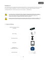
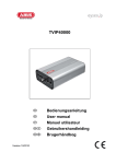
1. Scope of delivery
ABUS HD Network Camera
TVIP52501
Power supply
Mounting bracket
Quickguide
Software CD
including user manual
Video/audiocable
65
English
2. Installation
Make sure that all previous listed accessories were included in scope of delivery. In order to operate the
camera an Ethernet network cable is necessary. The cable has to comply with specifications of UTP
categories 5 (CAT 5) and must not exceed 100 meters of length.
2.1 Power supply
Before you start the installation make sure that the mains voltage and the nominal voltage of the camera
correspond.
2.2 Mounting the lens
The camera can be used only with CS mount lens.
In order to use Auto-Iris (AI) lens the connector for the cable can be found on the left side of the camera. You
can also use a manual lens. The camera will automatically recognize the type of lens. For the best possible
picture quality an AI lens is recommended.
The content of delivery for this network camera does not include a lens. Please ensure you are
using a suitable megapixel lens for camera operation.
2.3 Installing the camera
For installing the camera to wall you need to mount the camera bracket to the bottom of the camera. If the
installation of the camera is on a ceiling you first need to mount the socket to the top of the camera with the
included screws. You can then mount the camera bracket to the socket.
ATTENTION!
Make sure to disconnect the camera from the power supply during installation.
ATTENTION!
Never point the camera with opened iris towards the sun. This can damage the image sensor.
66
English
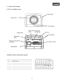
3. Camera description
3.1 Front view/Rear view
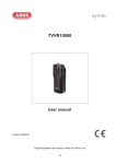
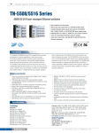
3.2 Alarm inputs and digital outputs
PIN
1
2
3
4
5
6
7
8
Descritption
+12V Output
Digital output
Digital input
Ground
24V AC input
24V AC input
RS-485 +
RS-485 -
Power
supply
Powe
wer su
upp
p lyy
Microphone
M
Mi
icrop
o ho
hone switch
swiitc
tch
iinternal/external
in
tte
ern
rnal
all//e
a
exter
xternal
xt
67
English
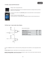
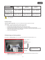
3.3 Video output and DIP switches
Analogue video output (NTSC/PAL):
Connect the RCA connector from the video/audio cable with an analogue video input from a
monitor. (e.g.: TVAC10100)
To set the correct video norm (PAL/NTSC) please use the DIP switch on the back panel of
the camera.
External / Internal microphone (Ext. /Int.)
Use this DIP switch to change between integrated microphone and external audio input.
3.4 Gate input / output and status display
Status LED description:
Status / LED colour
System start
Camera turned off
Network works (heartbeat)
Network problem
Firmware update
Restoring factory settings
Green
Off
Off
1/s
Off
1/s
0.1/s
Red
On
Off
On
On
0.1/s
0.1/s
In order to reboot the camera or restore the factory settings press the reset button. Use an appropriate small
tool.
Camera reboot: Press the reset button once and wait until the camera to restart.
Restore factory settings: Press and hold the reset button for approx. 30 seconds until the status LEDs start
flashing. All settings will be reset to factory default.
68
English
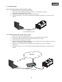
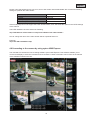
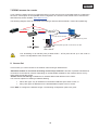
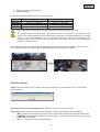
4. Initial start-up
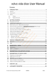
Direct connection between camera and PC / laptop
1. Make sure to use a crossover network cable
2. Connect the cable with the Ethernet port of the PC / Laptop and the camera
3. Connect the power supply to the camera
4. Configure the IP address of the PC / Laptop to 169.254.0.1
5. Continue with point 4.1 in order to finish the initial installing and build-up a connection to the
camera
c Crossed Ethernet cable
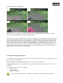
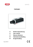
Connecting the camera by using a router / switch
1. Make sure to use a pair of patch cables
2. Connect the cable with Ethernet port of the PC / laptop with the router / switch.
3. Connect the cable with the network cable and with the router / switch.
4. Connect the power supply to the camera
5. f there is a name server (DHCP) available in your network then set the IP address of your PC /
laptop to “automatically receive IP address”
6. If there is no name server (DHCP) available set the IP address of your PC / laptop to
169.254.0.1
7. Continue with point 4.1 in order to finish the initial installing and build-up a connection to the
camera
Internet
Patch cable
69
English
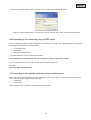
4.1 First camera access
The first camera access takes place by using the program „Installation Wizard 2“.
After starting the wizard it will automatically search the network for all connected EyeseoIP network cameras
and video servers.
You can find the program on the on the CD at CD-ROM\Tools\EyseoIP Tools\
Install the program on your PC and start it. The wizard will automatically search your network for EyseoIP
camera.
The IP address at factory default is 169.254.0.99. Without using the installation wizard you can only connect
to the camera if the IP address of the PC is between 169.254.0.1 and 169.254.0.98.
If a DHCP server is active in your network the IP address for your PC and camera will be set automatically.
Start now the installation wizard. If no DHCP server is active the installation wizard adds a virtual IP address
in the range of 169.254.0.xx. As long as the installation wizard is active you can access the network camera
by using the virtual IP address. We recommend adjusting immediately the cameras network settings to the IP
settings of the PC’s network.
After closing Installation wizard 2 the additional virtual IP adress will be removed. If IPCamera’s IP address is still in a different IP area then the one from your PC the camera access
is no longer possible.
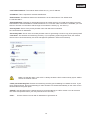
4.2 Connecting to the camera by using a web browser
If connecting to the camera by using Mozilla Firefox or Netscape a QuickTime stream will be displayed. This
requires that QuickTime from Apple is installed
In order to show the video stream when using Microsoft Inter Explorer a video plug-in is required. This will be
installed when connecting to the camera. A window will appear asking you to install the plug-in. Press the
install button to continue an install the plug-in. Depending on the security setup of the Internet Explorer the
installation might be blocked. In this case you need to adjust the security settings.
70
English
4.3 Installing the Active-X plug-in
For Mozilla Firefox or Netscape users, your browser will use Quick Time to stream the live
video. If you don’t have Quick Time on your computer, please download it first, then launch
the web browser.
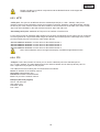
4.4 Adjusting the security settings
NOTICE!
The security settings of the Internet Explorer can prevent displaying the video stream. Change
at „Extras/Internet Options/Security“ to a lower level. Make sure to activate the ActiveX control
elements at “Custom Level”.
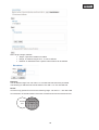
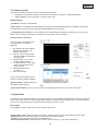
4.5 Password authentication
At factory default there is no admin password set for accessing the camera. For security reasons the
administrator should immediately set a password after the initial setup. After setting an admin password the
camera will request for every access a username and password.
The permanent default username for the admin will be „„root” and cannot be changed. The only way to reset
the password if it is forgotten is to reset the camera to factory default settings.
71
English
In order to access the camera enter username “root” and the before defined password.
-> After successful authentication you will connect to the camera and a video stream will be displayed.
4.6 Connecting to the camera by using a RTSP player
You can display the MPEG-4 video streams by connecting to the camera with a RTSP capable media player.
Following free media players support RTSP:
x
x
x
VLC Media Player
Real Player
QuickTime Media Player
The RTSP address has to be entered as following:
rtsp://<IP-address of the network camera>:<rtsp Port>/<Name of the video stream >
How to change the name of the video stream will be explained further on.
Example:
rtsp://192.168.0.99:554/live.sdp
4.7 Connecting to the network camera by using a mobile phone
Make sure that your mobile phone is able to establish a internet connection. Furthermore the mobile phone
has to have an RTSP capable media player like:
x
Real Player
x
Core Player
More information you can find in chapter “RTSP-Transmission”.
72
English
Please notice that limited access can occur, due to low mobile network bandwidth. We recommend following
settings to optimize the video stream:
Video compression
Resolution
I Frame
Video quality (constant bit rate)
Audio Compression (GSM-AMR)
MPEG-4
176x144
1 Second
40 Kbit / Second
12.2 Kbit / Second
If the media player does not support the RTSP authentication, then deactivate this option in the RTSP settings
of the camera.
The RTSP address has to be entered as following:
rtsp://<IP-address of the camera >:<rtsp Port>/<Name of the video stream >
How to change the name of the video stream will be explained further on.
Example:
rtsp://192.168.0.99:554/live.sdp
4.8 Connecting to the camera by using eytron VMS Express
The included CD contains the free recording software eytron VMS Express. This software enables you to
connect and display to several IP cameras and record these. Further information can be found in the manual
of the software located on the CD.
73
English
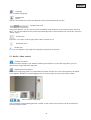
5. User functions
Open the main menu on the network camera. The interface is divided into the following main areas:
Control
Live image
Audio / video control
Live image
x
Change the zoom level by pressing the mouse scroll button.
x
Click in the live picture to take over control of an analogue pan/tilt camera directly.
Network camera control
Video Stream
Select from video streams 1 – 4 to view the live image.
Snapshot
Create a snapshot (without ActiveX plug-in).
Digital Output
Switch the digital output on and off manually.
Configuration
Configure the network camera (administrator settings).
Client Settings
Configure the client settings; you can find detailed information on the following pages.
74
English
Language
Set the interface language.
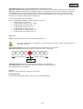
Pan/tilt/zoom
control
Use the control buttons to control the digital and mechanical pan/tilt/zoom function.
Variable view sizes
Using these buttons, you can choose from three different zoom levels for the live picture (100%, 50% and
25%). You can also adjust the live picture to automatically fit the current browser size. Do do this, select the
“AUTO” option.
Screen ratio
Press the “4:3” button to set the page ratio of the live picture to 4:3.
Show/hide menu
Global view
Here you can adjust the live image and navigate to single point of interests
5.1 Audio / video control
Variable view sizes
The web browser displays a new window containing the snapshot. To save the image file to your PC,
right-click the image and select “Save As”.
Digital zoom and snapshot
Click on the magnifying glass icon underneath the network camera view. The control panel for the digital
zoom appears. Disable the “Disable Digital Zoom” box and change the zoom factor with the slider.
Start / stop live image view
The live stream can be stopped (paused) or exited. In both cases, the live stream can be continued by
pressing the play symbol.
75
English
Local recording
A recording on the local hard disk can be started or stopped here. You can configure the recording path under
“Client Settings”.
Adjust the volume
Press to manually set the audio output level.
Audio On / Off
Talk
As long as this button is pressed, the audio signals from the PC are transmitted to the audio output of the
network camera.
Microphone volume
Press to manually adjust the level for the audio input of the network camera.
Mute
Press to switch the audio input of the network camera on and off.
Full-screen
Activates the full-screen view. The live image on the network camera is shown on the entire screen.
5.2 Client settings
The user settings are saved on the local computer. The following settings are available:
Media Options Allow the user to disable the audio or video function.
Protocol Options Allows a connection protocol to be selected between the client and the server.
The following protocol options are available for optimising the application: UDP, TCP, HTTP.
The UDP protocol gives you a larger number of audio and video streams in real time. However, some data
packets can be lost due to the large data volume in the network. Pictures may be unclear in this case.
The UDP protocol is recommended if you have no special requirements.
With the TCP protocol, fewer data packets are lost and the video display is more accurate. The disadvantage
of this protocol is that the realtime stream is worse than with the UDP protocol.
Select the HTTP protocol if the network is protected by a firewall and only the HTTP port (80) is to be opened.
The selection of the protocol is recommended in the following order: UDP – TCP – HTTP.
MP4 Saving Options: Here, you can modify the data path to save the data immediately. Activating the
“Add date and time suffix to filename” option generates files under the following name:
CLIP_20091115-164403.MP4
FileExtensionName_YearMonthDay-HourMinuteSecond.MP4
76
English
The recorded data can be played back using an MP4-compatible video player
(e.g. VLC Media Player).
6. Administrator Settings
6.1 System
Only the administrator has access to the system configuration. The following sections explain each of the
elements in the left-hand column. Specific tasks on the Options page are printed in bold. The administrator
can enter the URL under the picture to go directly to the pictures page of the configuration.
“Host name” This is the text that is shown as the title on the main page.
77
English
“Turn off the LED indicator” Select this option to switch off the LED display on the network camera.
This prevents other persons knowing that the network camera is in operation.
“Time Zone” Adjusts the time according to the selected time zone.
“Enable Daylight Saving Time” Activates daylight saving time settings in the network camera. The daylight
saving time settings for every time zone are already saved in the network camera.
“Keep current date and time” Choose this option if you wish to keep the current date and time of the
network camera. An internal realtime clock stores the date and time even after the system has been switched
off due to a power cut.
“Synchronise with computer time” Synchronises the date and the time of the network camera with the local
computer. The read-only date and time of the PC are displayed following the update.
“Manual” Sets the date and the time according to the administrator’s input. Note the date/time format when
entering in the respective fields.
“Automatic” Synchronises the date and time with the NTP server via the Internet every time the network
camera is switched on. This is not possible if the respective time server cannot be reached.
“NTP server” Assigns the IP address or the domain name of the time server. If you leave this text box empty,
the network camera is connected to the default time servers.
“DI and DO” Sets the pre-defined state for the alarm input and relay output.
Do not forget to press “Save” in order for your changes to take effect.
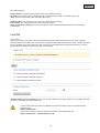
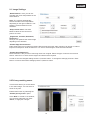
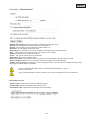
6.2 Security
“Root Password” Allows users to change the administrator password by entering a new password. For
security reasons, the passwords entered are shown as asterisks. After “Save” is clicked, the web browser
prompts the administrator to enter the new password for accessing the network camera.
“Add new user” Enter the new user
name and password and click “Add”.
The new user is displayed on the list
of user names. Up to twenty user
accounts can be configured.
“Edit users” Open the list of user
names, select the user that you wish
to edit, and change the required
values. To apply the changes,
click “Update”.
“Delete user” Open the list of user names, select a user and click “Delete”, to delete this user from the list.
78
English
User administration
Administrator: Complete unrestricted access to the network camera.
Operator: No access to the configuration page. Can also execute URL commands (e.g. PTZ).
User: Access is restricted to the main page (live view).
Digital Output: The user group can control the alarm input and output.
PTZ control: The user group has access to the PTZ control.
Allow anonymous viewing: There is no prompt for a user name and password when the main page
is displayed.
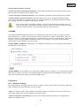
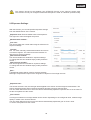
6.3 HTTPS
The HTTPS
protocol is used for encryption and for authenticating communication between the web server (network
camera) and browser (client PC) on the Internet. All data transmitted between the network camera and client
PC is encrypted using SSL. Apart from SSL encryption (compatible with all standard browsers), a source
authorisation certificate is required in order to use HTTPS.
“Enable HTTPS secure connection” You can choose between unencrypted (HTTP) + encrypted (HTTPS)
access or encrypted (HTTPS) access only.
If a secure HTTPS connection is enabled, the network camera can be accessed using the
following lines:
https:\\“IP-Adresse”
If you wish to stream using the HTTPS connection, use the following link:
https:\\“IP-Adresse”:“HTTPS-Port\Live.sdp
79
English
Creating and installing a certificate
“Create self-signed certificate automatically” The pre-defined certificate in the network camera is used.
With this option, no settings can be made by users.
“Create self-signed certificate manually” A new certificate is generated. Specific data must be entered.
“Create certificate request and install” Select this option if you wish to generate a certificate request
which is then submitted to a certificate authority. A certificate issued by a recognised certification authority
(e.g. VeriSign) can also be installed on the network camera.
Note: When using a “self-signed certificate”, you may receive a warning message from your
browser. Self-signed certificates are always classed as insecure by the browser as the source
certificate and authorisation of the certification authority are both absent.
6.4 SNMP
The Simple Network Management Protocol is a network protocol that can be used to monitor and control
network devices (e.g. routers, servers, switches, printers, computers etc.) from a central station. Here, the
Protocol controls the communication between the monitored devices and the monitoring station. Enable this
function if you are using an SNMP management server in your network. You can also access software
solutions that can be installed on your PC system.
“Enable SNMPv1, SNMPv2c” Depending on your SNMP server settings, you can define the name fields of
the read/write community here.
“Enable SNMPv3” If your SNMP server supports the SNMP protocol in version 3, you can execute the status
query with encryption. To do this, an encryption algorithm and password for the read/write community status
query must be saved in the network camera and SNMP server.
6.5 Network
6.5.1 Network settings
All changes made on this page cause the system to restart in order for the changes to take effect. Make sure
that the fields are correctly filled before you click “Save”.
“LAN” The default is LAN. Use this setting if the network camera is connected to a LAN. You also have to
make other settings such as the IP address or the subnet mask.
“Obtain an IP address automatically” Every time the network camera is restarted, it is assigned an IP
address via a DHCP server.
80
English
“Use fixed IP address” The network data is fixed here, e.g. the IP address.
“IP address” This is required for network identification.
“Subnet mask” This defines whether the destination is in the same subnet. The default value
is “255.255.255.0”.
“Standard-Router” Gateway for transmitting pictures to another subnet. An invalid router setting prevents
transmission to these destinations in different subnets. If a cross-link cable connection is available, you must
enter an IP which is in the same subnet range as the network camera (e.g. 192.168.0.1).
“Primary DNS” Server of the primary domain name with which the hostnames
are converted into IP addresses.
“Secondary DNS” Server of the secondary domain name for generating a reserve copy of the primary DNS.
“Use UPnP” This enables Universal Plug and Play. If your operating system supports UPnP, the network
camera can be accessed directly via UPnP management (Windows: network environment)
Make sure that the option “Use UPnP” is always enabled. UPnP is also used by eytron VMS to
search the network camera.
“UPnP port forwarding ON” Enables Universal Plug and Play port forwarding for network services. If your
router supports UPnP, then port forwarding for video streams is activated automatically on the router for the
network camera using this option.
“PPPoE” Use this setting if the network camera is connected directly to a DSL modem. You will receive a
user name and password from your ISP (Internet Service Provider).
“IPv6”
Use this function to work with IP addresses of generation v6.
81
English
Please note that your network and hardware must support IPv6.
If IPv6 is enabled, the network camera always waits until it is assigned an IPv6 address via DHCP.
If no DHCP server is available, set up the IP address manually.
To do this, enable “Manually setup the IP address” and enter the IP address, default router and DNS address.
“IPv6 Information” All the IPv6 information is displayed in a separate window.
If the IPv6 settings are correct, you can read all the settings in the lower window.
6.5.2
IEEE 802.1x
Activate this function if your network environment uses the standard IEEE 802.1x, a port-based access control
in the network.
IEEE 802.1x improves the security of local networks.
A connection is only permitted if all certificates between the server and “client” have been verified. They are
authenticated by a switch/access point, which sends queries to the RADIUS authentication server.
Otherwise no connection is made and access to the port is denied.
82
English
Please note that your network components and the RADIUS server must support the
standard IEEE 802.1x.
6.5.3 HTTP
“HTTP port” This port can be different from the standard port 80 (80, or 1025 – 65535). If this port is
changed, users must be informed to ensure a successful connection. Example: If the administrator changes
the HTTP port of the network camera with the IP address 192.168.0.99 from 80 to 8080, users have to enter
“http://192.168.0.99:8080” in the web browser instead of “http://192.168.0.99”.
“Secondary HTTP port” Additional HTTP port for the network camera access
For the direct access to individual video streams over the web, the following access names can be configured.
Access is gained via compressed JPEG images and allows web browsers (Firefox, Netscape) which cannot
process ActiveX plug-ins to access the video stream directly:
“Access name for stream 1” Access name for the MJPEG stream 1
“Access name for stream 2” Access name for the MJPEG stream 2
“Access name for stream 3” Access name for the MJPEG stream 3
“Access name for stream 4” Access name for the MJPEG stream 4
Note: Internet Explorer does not support the display of MJPEG images without Active
6.5.4 FTP
“FTP port” This is the internal FTP server port. It can be a different port to the standard port 21
(21, or 1025 – 65535). The video data saved on the network camera can be called up directly via FTP.
Use a separate FTP program for this purpose.
The address format for entering the connection data is as follows:
Server: IP address of the network camera
User name: Administrator user
Password: Password of administrator
Port: FTP port of the network camera
Example (with FTP program)
Server: 192.168.0.99
User name: root
Password: admin
Port: 1026
83
English
6.5.5
HTTPS
“HTTPS port” This is the port setting for the internal HTTPS port. It can be a different port to the standard
port 443 (443, or 1025 – 65535). You can find further configuration options for HTTPS in section 5.5.3.
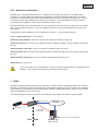
6.5.6
Two-way audio
“Two-way audio” This is the port for the two-way audio function. This port can be different from the standard
port 5060 (5060 or 1025 – 65535).
To be able to use the two-way audio function, you must enable “Video and audio” for the selected video
stream MPEG-4/H.264. MJPEG only supports the transmission of video data and is therefore not suitable for
this function.
Speaker
Microphone
Network / Internet
Ext.
Microphone
84
PCSpeaker
English
Live stream functions:
Start the audio data transmission.
Control the sensitivity of the network camera audio input.
Switch off the microphone/audio input.
Click the button again to stop the audio transmission.
6.5.7
RTSP transmission
“RTSP authentication” The authentication options are: disable (standard), basic (simple) or an expanded
mode (digest).
I If the RTSP authentication is enabled, the user name and password of a valid user
(e.g. administrator) must be entered during the RTSP connection setup.
IMPORTANT: The RTSP authentication must be supported by the video
(e.g. Realplayer 10.5).
player
“Access name for stream 1” This is the access name 1 for establishing a connection from a client.
The codec type must be MPEG4. Use
rtsp://<IP address>:RTSP port /<access name 1>, to establish a connection.
“Access name for stream 2” This is the access name 2 for establishing a connection from a client.
The codec type must be MPEG4. Use
rtsp://<IP address>:RTSP port /<access name 2>, to establish a connection.
“Access name for stream 3” This is the access name 3 for establishing a connection from a client.
The codec type must be MPEG4. Use
rtsp://<IP address>:RTSP port /<access name 3>, to establish a connection.
“Access name for stream 4” This is the access name 4 for establishing a connection from a client.
The codec type must be MPEG4. Use
rtsp://<IP address>:RTSP port /<access name 4>, to establish a connection.
RTSP access with VLC:
rtsp://192.168.0.99:10052/live.sdp
“RTSP port” This port can be different from the standard port 554 (554; or 1025 to 65535). If you change it,
note that the input format is analogue to the HTTP port.
“RTP port for video” This port can be different from the default port 5558. The port number must always
be even.
“RTCP port for video” This port must be the “RTP port for video” plus 1.
“RTP port for audio” This port can be different from the default port 5556. The port number must always
be even.
“RTCP port for audio” This port must be the “RTP port for audio” plus 1.
85
English
6.5.8 Multicast transmission
Multicast is the message transmission from a single point to a group (also known as a multiple-point
connection). The advantage of multicast is that messages can be transmitted simultaneously to several
recipients or a closed user group without the bandwidth of the sender increasing according to the number
of recipients. When using multicast, the sender only requires the same bandwidth as a single recipient.
The packets are multiplied on each network distributor (switch, router).
Multicast allows data to be sent efficiently to many recipients at the same time in IP networks. This is made
with a special multicast address. In IPv4, the address range 224.0.0.0 to 239.255.255.255 is reserved for
this purpose.
The following multicast settings can be configured for streams 1 - 4 in the network camera.
Enable “Always multicast” to use multicast.
“Multicast group address” Specifies a group of IP hosts which belong to this group
“Multicast video port” This port can be different from the default port 5560. The port number must always
be even.
“Multicast RTCP video port” This port must be the “Multicast video port” plus 1.
“Multicast audio port” This port can be different from the default port 5562. The port number must always
be even.
“Multicast RTCP audio port” This port must be the “Multicast audio port” plus 1.
“Multicast TTL” Time to Live
If you are setting up port forwarding in a router, all ports should always be forwarded this way
(RTSP + HTTP). This is imperative for successful communication.
7. DDNS
DynDNS or DDNS (Dynamic Domain Name System) is a system used for updating domain name entries in
real time. The network camera is equipped with an integrated DynDNS client, which updates the IP address
independently via a DynDNS provider. If the network camera is positioned behind a router, we recommend
using the DynDNS function on the router.
The following diagram offers an overview of accessing and updating the IP address using DynDNS.
d 195.184.21.78
c 192.168.0.3
Internet
e DynDNS
access data
f 195.184.21.78 Æ name.dyndns.org
LAN
WAN
DynDNS.org
Name Server
86
English
“Enable DDNS” Enables the DDNS function.
“Service providers” The provider list contains the hosts that provide DDNS services. Connect to the service
provider’s website to make sure that the service is available.
“Host name” This field must be completed if you want to use the DDNS service. Enter the host name
registered with the DDNS server.
“User name/email” The user name and the email address must be entered in this field to set up a connection
to the DDNS server or to inform users about the new IP address. Note: If you enter a “User name” in this field,
you must enter a “Password” in the next field.
“Password” To be able to use the DDNS service, enter your password in this field.
7.1 Setting up a DDNS account
Set up a new account at DynDNS.org
Save the account information
Note down your user data and enter this into the configuration of the network camera.
87
English
7.2 DDNS access via a router
If your network network camera is positioned behind a router, then access via DynDNS must be configured in
the router. A description of the DynDNS router configuration for common router models can be found on the
ABUS Security-Center website: www.abus-sc.com.
The following diagram offers an overview of accessing a network camera behind a router via DynDNS.org.
g 192.168.0.1
f 195.184.21.78:1026
Internet
e 195.184.21.78:1026
c http://name.dyndns.org:1026
d name.dyndns.org:1026 Æ 195.184.21.78:1026
LAN
WAN
DynDNS.org
Name Server
Port forwarding of all relevant ports (at least RTSP + HTTP) must be set up in the router in
order to use DynDNS access via the router.
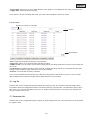
8. Access list
This is where you control access to the network camera using IP address lists.
“Maximum number of concurrent streaming connection(s) limited to” Number of possible simultaneous
connections to the network camera. Depending on the bandwidth available for the network camera, it may
make sense to limit the access.
“Enable access list filtering” Enables the IP address filters listed defined under “Filters”
You have two options for defining IP address filtering:
x
x
“Allow” filter type: only IP addresses in the defined address space have access, or
“Deny” filter type: IP addresses in the defined address space have no access.
Click “Add” to configure the address ranges. The following configuration options are given:
88
English
Rule: Single, Range, Network:
x Single: a specific IP address is added
x Range: IP address ranges from - to can be defined
x Network: IP addresses with a specific subnet mask can be defined
Example:
The IP address range from 192.168.0.1 to 192.255.255.255 should be permitted.
The following IP addresses should be blocked 192.168.1.0 to 192.168.255.255.
Result:
Access is only granted for IPs from the following range: 192.168.0.1 – 192.168.0.255.
An intersection is formed between IPs which are allowed access and denied access.
Access
list
Blocked
IPs
89
English
9. Audio and Video
“Video title” The text appears in the black bar above the video window with a timestamp. This timestamp
(date and time) is provided by the integrated realtime clock of the network camera.
“Colour” Choose between colour and black and white display.
“Modulation” Select between the video standard NTSC and PAL or automatic video signal recognition via
the network camera.
“Select caching stream” The selected video stream is used for recording the pre- and post-alarm video data
(see “Application” section).
“Flip” Rotates the video horizontally. Select this option if the camera has been installed upside down.
“Mirror” Rotates the video vertically.
Select the flip and mirror options if the camera is installed on the ceiling.
“Overlay title and time stamp on video and snapshot” You can use this option to display the title and time
stamp directly in the video image and snapshots. The input for “Video title” is used here.
90
English
9.1 Image Settings
„White Balance“: Here you can set
manually the colour temperature for the
white balance:
Auto: The camera automatically
selects the ideal colour temperature
depending on the light conditions. This
setting is recommended for most
situations.
“Keep current value” The white
balance values of the current live
picture are used
„Brightness, Contrast, Saturation,
Sharpness“:
Here you can optimize the video imiage
depeding on the situation.
“Enable Edge Enhancement”:
Edge enhancement is an image processing filter that enhances the edge contrast of an image or video to
improve its sharpness. Enter a value from 1 to 128 to set the degree of enhancement desired.
“Enable Noise Reduction”:
Noise reduction is the process of removing noise from a signal. Select the type of noise to remove and
enter a value from 1 to 63 to set the degree of enhancement required.
In order to see the changed settings click the „Preview“ button. To change the settings press the “Save”
button. In order to discard the settings press the „Restore“ button.
9.2 Privacy masking zones
This function allows you to hide areas
in the video image. You can select 5
areas of any size.
Enable this function by selecting the
“Enable privacy mask” option.
Click “New” to create a new window;
you can then adjust the size. Click
“Save”, to apply the changes.
91
English
This function should not be enabled if the PTZ/ePTZ function of the camera is being used.
This function can only be configured if MS Internet Explorer is used as a browser (ActiveX mode).
9.3 Exposure Settings
With this function you can set specified exposure settings
from the CMOS-Sensor of the camera.
„Exposure level“ Sets the default value of the aperture.
The higher the value the brighter the picture.
„Measurement window“:
„Full view“
The camera takes the overall video image as reference for
exposure settings.
„Custom“
You can add manually customized windows as inclusive
or exclusive regions. The camera uses this windows as
reference for exposure settings.
„Add inclusive window“
The camera inludes this window for exposure settings.
To change the format of window simply modify it with the
mouse.
„Add exclusive window“
The camera ignores this window for exposure settings.
To change the format of window simply modify it with the
mouse.
„BLC“
A predefined window will be used for exposure settings.
Back light compensation improves the recognition of objects in front of ligth sources.
„Exposure time“
The shorter the time is set, the less light will be applied to the sensor and the image becomes darker. The
picture sharpness during fast movements decreases because of longer exposure time.
You can either define an area in which the camera automatically adjust the exposure time or fix the value.To
set the zone please use the mouse.
„Gain control“
In low light conditions more image details can be shown. Depending on the configured value, a better image
quality in a dark room can be achieved.
You can either define an area in which the camera automatically adjusts the gain or fix the value.
To set the zone please use the mouse.
92
English
Usage of Sensor profiles:
The network camera supports different sensor profiles, depending on situation or time. Next to the standard
profile following can be configured:
x
Day:
Use this profile if the network camera is installed at a location with permanent
daylight conditions.
x
Night:
Use this profile if the network camera is installed at a location with permanent low
light conditions.
x
Schedule: Here you can select a schedule. The settings will only be active within this
timeframe.
9.4 Basic setting:
Video options
The network camera has four video streams with different quality settings available for flexible application.
Settings for streams 1, 2, 3 and 4
You can configure streams 1 – 4 in the respective menus.
The quality settings for stream 4 is determined on QCIF. Use stream 4 for streaming on mobile
devices.
“Image compression” Select from H.264/MPEG-4/MJPEG.
“Image size” Select your desired resolution here.
“Max. image rate” Select your maximum refresh rate here.
“Key frame interval” Determines how often an Intra Frame is generated. The shorter the interval, the better
the image quality, and the higher the network usage costs.
“Video quality fixed image rate” Sets the image rate at a constant value. The image quality is reduced the
more complex an image is (e.g. motion).
“Fixed image quality” Sets the image quality at a constant value. The bit rate increases with the image
complexity (e.g. motion).
93
English
Compression
Recording duration
1 minute
video sequence
in Full HD resolution
with “good” quality
Storage capacity
32 GB SD card
H.264
MPEG-4
MJPEG
Approx. 30 MB
Approx. 55 MB
Approx. 220 MB
Approx. 18 hours
Approx. 10 hours
Approx. 2,5 hours
At the end of the manual you can find a detailed table with every quality setting combined with
every resolution.
Day/Night settings:
„Switch to B/W in night mode “: Here you can switch the network camera to b/w mode.
„IR cut filter“: There are following option to switch the IR cut filter:
x Auto: Automatic switching from colour to b/w below 2 Lux.
x Schedule mode: Automatic switching from color to b/w at fixed times.
x Day mode: Manual activating of the day mode. The IR filter is switched to block all IR light.
x Night mode: Manual activating of the night mode. The IR filter is removed to allow IR light to pass and
improve the image quality in low light conditions.
x Synchronize with digital input
9.5 Adjust image and viewing window
By clicking on „viewing window“ you can configure the resolution for the video streams 1 to 3.
Coverage: 1920x1080
(during individual image
area)
1. Select the stream you want to configure. Stream 4 always provides the full image area and is
therefore not selectable
2. Select a resolution from the dropdown menu.
94
English
3. Adjust the image area to the ROI.
4. Save the settings.
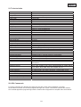
Folgende maximale Einstellungen können gesetzt werden:
Stream1
Stream2
Stream3
Stream4
Image area
176x144 – 1920x1080
176x144 – 1920x1080
176x144 – 1468x1200
1920x1080 (fix)
Image size
176x144 – 1920x1080
176x144 – 1920x1080
176x144 (fix)
1920x1080 (fix)
For viewing and recording the IP camera with eytron VMS always stream 1 is used.
The network camera functions using a 16:9 image sensor. If you select a 16:9 resolution under
ROI, the live image displayed by the camera will be distorted by recording software or a recorder
system, or may not be displayed at all. To solve the problem, you must set a 4:3 resolution in the
network camera or ROI: 320x240, 640x480, 800x600 or 1024x768. This may involve cropping the
periphery of the live image.
After setting up a ROI only this area will be displayed at live display as well as for RTSP access (e.g using
VLC media player). By transmitting only the ROI bandwidth and storage space is saved.
ROI
9.6 Audio settings
“Mute” All audio functions in the network camera are deactivated. A note appears when you access the
network camera.
“External microphone/audio amplification” Adjust the value from +21 db to -33 db.
“Audio type” Select the audio type and desired bit rate. A higher value requires more bandwidth:
x “AAC” (Advanced Audio Coding) Special codec for audio data compression under MPEG-4/H.264.
x “GSM-AMR” (Global System for Mobile Communications – Adaptive Multi Rate) Voice codec in GSM
mobile telephone network.
x “G.711” pmca/pmcu (Pulse Code Modulation).
95
English
10. Motion detection
You can activate up to three motion zones in the network camera. Select “Enable motion detection”, to
configure the function.
The motion detection function is only active once you have defined an action under the
“Application” menu item.
“Window Name” The text appears at
the top of the window.
“Sensitivity” Sensitivity in changes of
picture sequence (e.g.: sensitivity high:
triggering by slight picture change).
“Percentage” Specifies the percentage
of the image that has to change for the
motion sensor to be triggered.
Click “New” to add a new window. To
resize the window or move the title bar,
click the window frame, keep the mouse
button pressed and drag the window to
the required size. Close the window by
clicking the “x” in the top right corner.
Click “Save” to save the window settings. A bar graph rises or falls according to the picture variation.
A green bar means that the picture variation is below the surveillance level, whilst a red bar means that the
picture variation is above the surveillance level. If the bar is red, the detected window appears with a red
frame. When you return to the homepage, the monitored window is hidden. As soon as motion is detected,
the red frame is displayed.
30% Prozent
Green area: Motion recognised, however alarm is not triggered.
Red area: Picture variation (motion) exceeds the limit value of 30% and triggers an alarm.
96
English
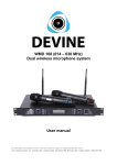
Functionality of motion detection:
A
C
B
D
Two parameters are available for configuring motion detection: Sensitivity and percentage. The figure
shows how these two parameters influence motion detection.
A motion occurs, shown in the progression from figure A to figure B. The resulting pixel changes (depending
on the sensitivity setting) are shown in figure C (grey). The “Sensitivity” setting refers to the capacity of the
sensor to detect motion in the picture. The higher the set value, the more pixel changes are detected in the
picture. When motion is detected, the pixel changes (depending on the sensitivity setting) are saved on the
server as alarm pixels (pink areas in figure D). The “Percentage” value describes the percentage of the
“alarm pixels” in relation to the total number of pixels in the selected area. If the specified percentage of alarm
pixels is reached or exceeded, an alarm is triggered. To ensure reliable motor detection, a high sensitivity
setting and low percentage value is recommended.
11. Camera tampering detection
The network camera supports tampering detection. If detection is enabled, the alarm can be used as an event
for a notification (see “Application”).
“Enable network camera tampering detection” The sensor system is activated.
“Triggering behaviour” The period defines how long a tampering event must continue before an alarm
is triggered.
The following tampering events are checked:
x
Camera rotation
x
Camera masking
x
Camera defocussing
You can set tampering detection as a trigger in the camera function “Application/Event setup”.
97
English
12. Camera control
There are two different options to control PTZ network cameras:
x
Mechanical: Connect the Network Camera to a PTZ driver or scanner via RS485 interface.
x
Digital: Digital PTZ (e-PTZ) within a certain image area.
RS485 Settings
„Disabled“: Function is deactivated.
„PTZ camera“: This setting is required when connecting a motorized pan/tilt driver via RS485. Choose the
corresponding protocol: Pelco-D, DynaDome/SmartDOME, Lilin PIH-7x00.
„Transparent HTTP Tunnel“: If your PTZ device accepts RS485 commands via network you can use this
option. The necessary parameters you will find in the manual of the PTZ device.
Preset positions and tours
You can set up a maximum of 20
preset positions. Proceed as
following:
1. By using the direction buttons
position the camera tot he
desired image area.
2. Enter a name for this preset.
The name will be displayed in
the preset list.
3. Repeat steps 1 to 3 to add
further preset positions
4. To add presets to a tour mark
these in the preset list and
press „Select“.
5. Adjust the dwell time if
necessary.
6. Save the settings.
c
d
f
g
If you are using the digital control
there are further settings available:
„Select stream“: Adjust settings for
the selected video stream.
„Zoom times display“: Here you can choose if to display the zoom ratio into the live view image.
13. Application
This allows you to automate tasks in the network camera. The application configuration comprises 3 sections:
event, server and medium. A typical application example may look like the following: due to motion detection
(event), an email (server) with an alarm picture (medium) is sent to a user.
Event setup
Click “Add” to create a new event. Up to 3 events can be set.
“Event name” Assign a unique name to the event, under which the event configuration is to be saved
“Enable this event” Select this option to activate the programmed result.
“Priority” Events with higher priority are completed first
“Detect next event after” Time between events to be executed (e.g.: with motion detection)
98
English
13.1 Trigger settings
“Video motion detection” Activate the desired motion window.
“Periodically” The event is triggered periodically. Maximum setting is 999 minutes.
“Digital input” Triggered if a signal is present at the alarm input (e.g.: door contact).
“System boot” Event is triggered when the system is rebooted (after a power failure).
“Recording notify” If the destination storage (medium) is full or if a cyclic recording is overwritten, an alarm
is triggered.
“Camera tampering detection” An alarm is triggered if the system detects that the connected analogue
camera has been tampered with.
“Video loss” An alarm is triggered if the video signal is interrupted.
“IP changed” As long as a new IP address is assigned to the network camera, an alarm is triggered.
“Video restore” Triggered when the video signal is restored following a malfunction.
99
English
Event schedule
“Sun” – “Sat” allows you to select the day of the week for executing an event.
“Always” Activates the event at all times (24 hours).
“From” – ಯto” The event times are restricted.
13.2 Server configuration
You can save up to 5 servers in the network camera. Click “Add” to configure a new server. The server of
type “SD” is pre-configured and defines the SD card unit as the destination for saving data. You can
configure the following server types:
x
x
x
x
Email: enter the access data here
FTP: enter the access data here. Address convention: ftp.abus-sc.com
HTTP: enter the access data here. Address convention: http://abus-sc.com/cgi-bin/upload.cgi
Network storage: Address convention: \\192.160.0.5\NAS
Once you have entered the access data, save your settings. Before closing the window, it is advisable to
execute a “Test”. The result is displayed in a new window of the browser.
100
English
13.3 Media settings
You can save up to 5 media settings in the network camera.
“Media name” Unique name for the medium.
There are 4 different media types:
x Snapshot (JPEG file)
x Video clip (MP4 format)
x System log (TXT log)
x Custom message (TXT format)
Each medium that you create can only be linked with one event.
Assigning a medium twice results in the incorrect functioning of the network camera.
If you wish to use the same media type for two events, you must create two separate media
types beforehand.
Snapshot
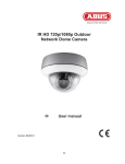
“Source” The recording can be made from video streams 1–4.
“Send pre-event image(s)” Number of snapshots before an event.
“Send post-event image(s)” Number of snapshots after an event.
1
2
3
4
5
Pre-event images
6
7
8
9
Post-event images
Trigger
101
English
“File name prefix” Enter a name that will prefix the snapshot file name.
“Add date and time suffix to file name” Adds the date and time to the snapshot so that you can more easily
distinguish between the file names of snapshots either in sequential or event-controlled operation. Example:
“video@20030102_030405.jpg” means that the JPEG picture was taken on January 2, 2003 at 03:04:05
(i.e., just after 3:04 am). If you omit this suffix, the file is updated with the name “video.jpg” on the external
FTP server according to the specified time interval.
The data name is structured as follows:
Prefix_YYYYMMDD_HHMMSS : ABUS_20091115_164501
x Prefix: see file name prefix
x Y: placeholder for year, YYYY = 2009
x M: placeholder for month, MM = 11
x D: placeholder for day, DD = 15
x H: placeholder for hours, HH = 16
x M: placeholder for minutes, MM = 45
x S: placeholder for seconds, SS = 01
Video clip
“Source” The recording can be made from video streams 1-4.
The video stream that is configured in “Audio and Video” under “Select caching stream” is
offered as a source.
“Pre-event recording” Pre-event recording interval in seconds (max. 9 seconds).
“Maximum duration” Maximum duration for each file (max. 10 seconds).
1
2
3
4
5
6
7
8
9
Post-alarm memory
Pre-event memory
Trigger
“Maximum file size” Maximum size of the file in kByte (max. 800 kByte).
“File name prefix” Enter a name that will prefix the video recording file name.
(see snapshot section for details)
Log file
Saves the current system log contents in a text file.
Custom Message
A user-defined message in the form of a text file is sent additionally.
102
English
13.4 Action
Here, you can configure the action that is to be executed if an alarm has been triggered.
“Trigger digital output for” When this option is enabled, the relay output for the network camera is
activated.
“Move to preset location” A preset location is activated when the alarm is triggered.
“Server” the selected medium is sent on a particular server (e.g. an email is sent with a snapshot).
“Create folders automatically” Folders are automatically created in the directory of the network drives
“Customized folder” The unique name of the folder is determined using variables.
The variables that are available can be found in the table below.
Symbol
Example/function
/
%IP = IP address
%N = Event name
%Y = Year
%M = Month
%D = Day
%H = Hour
“Example text”
Create a new folder
192.168.0.1
Motion_W1
2010
03
04
14
“Example text”
Example:
The following entry would generate this path.
103
English
13.5 Application overview
Here, you can view all the “Events”, “Media types” and “Servers” that are configured in the network camera.
You can check, delete and add the different settings here.
You can also check the different parameters such as name, status, trigger, address.
14. Recording
The recording section allows you to set up recordings with the option of setting up permanent video
recordings for SD cards or network shares. You can save up to 2 video settings in the network camera.
Click “Add” to create a new recording.
104
English
Destination: “Network drive”
“Recording name” A unique name for a recording entry.
“Enable this recording” Select this option to activate the recording entry.
“Priority” Recordings with a higher priority are executed first.
“Source” The recording can be made from video streams 1-4.
“Schedule” The recording schedule is used.
“Network fail” If a network error occurs, the data is automatically saved onto SD card.
“Sun” – “Sat” allows you to select the day of the week for a recording.
“Always“ Activates the recording at all times.
“From“ – “to” The recording times are restricted.
“Destination” SD card or network folder.
“Entire free space” The maximum amount of space on the destination storage medium is used.
“Reserved space” Defines how many MB of free memory space should be reserved.
“Enable cyclic recording” Activates the cyclic recording function. If the set value is reached during the data
recording, the oldest data is overwritten.
For more detailed information about “Create folders automatically”, refer to
section “13.4 Action”.
If the “Customized folder” option is enabled, the cyclic recording function cannot be used.
Recording overview
“Name (video)” Opens the recording configuration page.
“Status (ON)” Sets the recording status to ON or OFF.
“Destination (SD)” Opens a file list with the saved recordings.
105
English
15. Local memory
This section explains how you can manage the local memory (SD card) of the network camera. Cards of type
SD/SDHC Class 6 of up to 32 GByte are supported.
SD card management
Use the “Format” function if you are using the card in the network camera for the first time.
Select the “Enable cyclic storage” option if the oldest data should be overwritten when the storage capacity
of the SD card is full.
If you select “Enable automatic disk cleanup”, the contents of the SD card are deleted after the maximum
duration for keeping files is reached.
Searching and viewing the records
If no criteria are selected, the list of results will always include all recordings.
106
English
“Trigger type” Select one or more characteristics which apply to a recording that was made on the SD card.
“Trigger time” Select the desired period.
Click “Search”. All the recordings that meet your criteria are displayed in the list of results.
List of results
Number of entries on one page
Search
Scroll pages
“View” Shows the selected recording in a new window.
“Download” Allows you to download the selected recording.
“JPEGs to AVI” You can select several JPEG single picture recordings (selection box) and convert these into
an AVI file.
“Lock/Unlock” Individual recordings can be locked. Locked recordings will not be overwritten through cyclic
storage. Press the button again (unlock) to remove this attribute.
“Remove” The selected recording is deleted.
You can also evaluate the data stored on the SD card using the SD card reader on your PC. The recorded
data is displayed according to file type with the date and time in the file name.
16. Log file
Click this link on the configuration page to display the system log file. The contents of the file supply useful
information about the configuration and the connection following a system start. The standard of the log file is
RFC 3164. You can also send data to a log server. Enable “Remote Protocol” and enter the IP address and
the port number of the server.
17. Parameter list
Click this link on the configuration page to display all system parameter sets. This information can be provided
for support cases.
107
English
18. Management
Reboot
Press the “Reboot Now” button to restart the network camera. You can also configure an automated device
reboot. This may be helpful if network problems occur. We recommend rebooting the network camera on a
weekly basis if you experience problems.
Restore
Click to restore the factory settings. All previous settings are discarded.
Export files
Press to export your network camera settings into a file. You can also export and save the daylight saving
time configuration file.
Upload files
Press “Browse...” and select the correct configuration file.
Then press “Upload” and wait until the settings have been restored.
108
English
Upgrade firmware
Like an update with the installation wizard, you can update the firmware of the network camera here. You can
download the latest firmware from www.abus-sc.com. Select the firmware file (*.pkg) and press “Upgrade”.
The update takes a short time. When you restart the network camera, it is started with the new firmware.
Never disconnect the network camera from the power supply during an firmware upgrade,
otherwise you risk causing irreparable damage.
A firmware upgrade can last up to 10 minutes.
19. Maintenance and Cleaning
19.1 Function Test
Regularly check the technical safety of the product, e.g. check the housing for damage.
If safe operation is no longer possible, cease operating the product and safeguard it against
accidental operation.
Safe operation is no longer possible if:
x
x
x
x
the device shows visible damage,
the device no longer functions, and
the device has been stored in adverse conditions for a long period of time, or
the device has been subject to stress during transportation.
This product is maintenance-free for you. There are no components to service or anything
inside the product to check. Never open it.
19.2 Cleaning
Clean the device with a clean, dry cloth. The cloth can be dampened with lukewarm water if it gets dirty.
Make sure that liquid does not get into the inside of the device as this will cause damage.
Do not use any chemical cleaning products as this could damage the surface of the housing.
20. Disposal
Devices that have been marked accordingly may not be disposed of as domestic waste. At
the end of its service life, dispose of the product according to the applicable legal
requirements.
Please contact your dealer or dispose of the products at the local collection point for
electronic waste.
109
English
21. Technical data
Model number
Camera type
Image Sensor
Resolution
Pixels (total)
Pixels (effective)
Lens
Digital zoom
Day/night switch-over
Image compression
Frame rate
Video out
Number of parallel streams
Number of maximum users
Minimum lighting (color)
Electronic shutter
Motion detection
Pre-alarm/post-alarm memory
Image overlay
Alarm inputs (NO/NC)
Digital output
Audio
Backlight compensation
Microphone
White balance
Alert message
Supported browsers
Software supported
SD card
RS-485 port
PTZ protocols
Network connection
Network protocols
Encryption
Access protection
Power supply
Current consumption
Operating temperature
Dimensions (W x H x D)
Certification
TVIP52501
Network camera
1/2.7" CMOS Progressive Scan Sensor
176 x 144 – 1920x1080 (intermediate levels can be freely selected)
1920x1080
1920x1080
CS mount for lens, DC connector
4x
Mechanically removing IR cut filter
H.264, MPEG-4, MJPEG
H.264 1920x1080@25FPS
MPEG-4 1920x1080@25FPS
MJPEG 1920x1080@25FPS
Yes ,PAL or NTSC
4
10
0,8 Lux
1/5 - 1/40.000 seconds
3 zones
Yes
Date, camera name, private zones
1
1 (12VDC@400mA)
Audio output (Speaker Out), audio input, 2-way audio
Yes
Integrated
Yes
E-mail / FTP / HTTP notification / relay output / NAS drive / SD card
Mozilla Firefox or Internet Explorer 6.x and higher
eytron VMS, ONVIF support
max. 32 GB (SD/SD-HC)
Yes
Pelco D, Pelco P, LiLin, Samsung scc643, DynaDome /
SmartDome
RJ45 Ethernet 10/100 Base-T with PoE
IPv4, IPv6, TCP/IP, HTTP, UPnP, RTSP/RTP/RTCP, IGMP, SMTP,
FTP, DHCP, NTP, DNS, CoS, QoS, SNMP, 802.1X
HTTPS SSLv3
IP address filter, user name, password, 3 authorisation levels
12 VDC, 24 VAC, 802.3af PoE
Max. 5.0 Watt
0 °C ~ 40 °C
76 x 60 x 162 mm
CE, RoHS, C-Tick
22. URL Commands
For some customers who already have their own web site or web control application, the video
server/Network camera can be easily integrated through URL syntax. This section specifies the external
HTTP-based application programming interface. Please refer to Appendix for complete URL command list.
110
English
23. License information
We point at the fact that thenetwork cameras TVIP52501 among other things include Linux software source
codes that are licensed under the GNU General Public Licence (GPL). To assure a GPL compliant usage of
the used source codes we point at the licence terms of GPL.
Licence text
The licence text of the GNU General Public Licence can be found on the included software CD or on the
ABUS Security-Center Homepage under http://www.abus-sc.de/DE/Service-Downloads/Software?q=GPL
Source Code
The used source codes are available on the ABUS Security-Center Homepage under
http://www.abus-sc.de/DE/Service-Downloads/Software?q=GPL
for free download.
Operation of the total system
With a download of the software packages (source codes) it is not possible to built a running total system.
Therefore additional software applications and the network camera hardware is needed.
24. Technologie Lizenzhinweise
H.264, MPEG-4 AAC Technology
THIS PRODUCT IS LICENSED UNDER THE H.264, MPEG-4 AAC AUDIO PATENT LICENSE. THIS
PRODUCT MAY NOT BE DECOMPILED, REVERSE-ENGINEERED OR COPIED, EXCEPT REGARD TO
PC SOFTWARE, YOU MAY MAKE SINGLE COPIES FOR ARCHIVAL PURPOSES. FOR MORE
INFORMATION, PLEASE REFER TO HTTP://WWW.VIALICENSING.COM.
H.264, MPEG-4 Visual Technology
THIS PRODUCT IS LICENSED UNDER THE H.264, MPEG-4 VISUAL PATENT PORTFOLIO LICENSE FOR
THE PERSONAL AND NON-COMMERCIAL USE OF A CONSUMER FOR (i) ENCODING VIDEO IN
COMPLIANCE WITH THE MPEG-4 VISUAL STANDARD ("MPEG-4 VIDEO") AND/OR (ii) DECODING
MPEG-4 VIDEO THAT WAS ENCODED BY A CONSUMER ENGAGED IN A PERSONAL AND NONCOMMERCIAL ACTIVITY AND/OR WAS OBTAINED FROM A VIDEO PROVIDER LICENSED BY MPEG LA
TO PROVIDE MPEG-4 VIDEO. NO LICENSE IS GRANTED OR SHALL BE IMPLIED FOR ANY OTHER
USE. ADDITIONAL INFORMATION INCLUDING THAT RELATING TO PROMOTIONAL, INTERNAL AND
COMMERCIAL USES AND LICENSING MAY BE OBTAINED FROM MPEG LA, LLC. SEE
HTTP://WWW.MPEGLA.COM.
AMR-NB Standard
THIS PRODUCT IS LICENSED UNDER THE AMR-NB STANDARD PATENT LICENSE AGREEMENT.
WITH RESPECT TO THE USE OF THIS PRODUCT, THE FOLLOWING LICENSORS’ PATENTS MAY
APPLY:
TELEFONAKIEBOLAGET ERICSSON AB: US PAT. 6192335; 6275798; 6029125; 6424938; 6058359.
NOKIA CORPORATION: US PAT. 5946651; 6199035. VOICEAGE CORPORATION: AT PAT. 0516621; BE
PAT. 0516621; CA PAT. 2010830; CH PAT. 0516621; DE PAT. 0516621; DK PAT. 0516621; ES PAT.
111
English
0516621; FR PAT. 0516621; GB PAT. 0516621; GR PAT. 0516621; IT PAT. 0516621; LI PAT. 0516621; LU
PAT. 0516621; NL PAT. 0516621; SE PAT 0516621; US PAT 5444816; AT PAT. 819303/AT E 198805T1;
AU PAT. 697256; BE PAT. 819303; BR PAT. 9604838-7; CA PAT. 2216315; CH PAT. 819303; CN PAT.
ZL96193827.7; DE PAT. 819303/DE69611607T2; DK PAT. 819303; ES PAT. 819303; EP PAT. 819303; FR
PAT. 819303; GB PAT. 819303; IT PAT. 819303; JP PAT. APP. 8-529817; NL PAT. 819303; SE PAT.
819303; US PAT. 5664053. THE LIST MAY BE UPDATED FROM TIME TO TIME BY LICENSORS AND A
CURRENT VERSION OF WHICH IS AVAILABLE ON LICENSOR’S WEBSITE AT
HTTP://WWW.VOICEAGE.COM
112