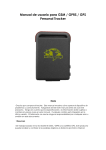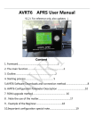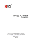
1
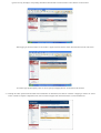
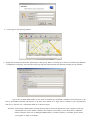
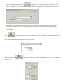
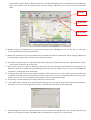
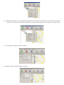
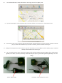
Operation Instructions about Monitor Center
(1)
GPRS Initiation
Step I:
1.1 Load a GSM SIM card into the tracker and subscribe the GPRS service. Please make sure that the SIM card is able to execute the function of
incoming calls display , no calls can be diverted and the PIN code is locked.
1.2 Place the SIM card into the slot of the tracker and then turn it on.
1.3 monitor software run in the circumstance of Windows NT/2000/2003/XP。
Step II: APN Configuration
2.1 APN standards for Access Point Name and differs from country to country. For more information about the local APN, inquire with your local
GPRS network operator. or visit http://www.mdtu.com/bbs/dispbbs.asp?boardid=11&Id=31755&page=1&star=1 to
check. .Text the tracker a SMS “APN123456 + Space + your local APN” via a cell phone and if succeeded in setup, the tracker will return the
message “APN OK”. If failed, namely, the SMS “APN FAIL” is received, check out the format of commands sent and password as well.
eg. Send SMS command “APN123456 CMNET”. If succeeded, “APN OK” is returned by the tracker in SMS.
Notes: 123456 refers to password and CMNET APN's Network Operator of China.
Step III: IP Address and Port Setup
3.1 Send SMS as below via a cell phone: adminip + 123456 + Space + IP Address + Space + Port Number.
If succeeded, “adminip OK” is
returned by the device in SMS. For example, send SMS command "adminp123456 21.34.116.58 7070" to the tracker. If configuration goes
smoothly, the tracker returns "adminip OK"; If there is something wrong when SMS “adminip fail” is received, check out the format of
commands sent and password as well.
Note: 123456 refers to password,
21.34.116.85 IP address of the public network to which the computer installed the monitor center software pertains, 7070 the port receiving
GPRS data of the monitor center software. The abovementioned port corresponds to an idle computer port.
3.2 How to obtain a public IP address?
3.2.1 For ADSL subscribers with routing function disenabled, right-click the My Network Place in the Windows NT/2000/2003/XP, click
Properties and then select Local Connection in the subsequently popped up window for network connection. At this movement, your public IP
address appears in the left lower corner.
3.2.2 For ADSL subscribers with routing function enabled, the current IP address refers to an internal IP address such as 10.x.x.x, 172.x.x.x and
192.168.x.x and so on. Therefore, they are all internal subscribers. In order to obtain a public IP address, it is required first of all to find out
the IP address of the router (the router IP address is a proprietary IP address rather than a public IP address). Type in the router IP address into
the location field of the IE explorer and then log into the configuration interface of the router following entering the user name and password
of the router. Due to different manufacturers, the router configuration interface may differ from ether other. It is strongly recommended you to
read through the user’s manual of router.
Attention: As your public IP address is not fixed but dynamic, it changes each time when surfing the internet via dial-up internet access, thus
directly resulting in failure of GPRS connection. In such a case, it needs to set up current IP address via following the Step III. If your IP
address is fixed, there is no need to consider troubles mentioned before and once set up, it can remain valid for a long-term.
3.3 Which are ports that can be configured?
They range from 1024 to 65535 in number and are not allocated to certain service without alteration, this is to say, many services can use one port.
Deploy the command Netstat in the Windows 2000/XP/Server 2003 to examine ports in use.
Click “Start/Run” in turn and then put “cmd” into the field to open the command prompt symbol window. Type in “netstat –a -n” and then press
Enter to display the number and status of port in connection with TCP and UDP in the format of digits.
All the ports displayed in the interface are occupied and not available for use. Select any number within the range of 1024~65535 other than
those numbers displayed in the interface.
Attention: The ports in the tracker, router and system setup of the map monitor center should be identical.
Step IV: GPRS Login User Name and Password Configuration
4.1
In most countries, the user name and password involving GPRS login are not compulsorily necessary. Therefore, the entry can be skipped.
For those countries requiring user name and password, please configure as follows:
Send SMS“up + 123456 + Space + User + Space + Password”. If succeeded, “user, password OK” is returned by the tracker in SMS. For
instance, send SMS “up 123456 Jonnes 666666” to the tracker, and if succeeded, the tracker returns "user, password OK".
”
Notes: 123456 refers to password of the tracker, Jonnes user name and 666666 GPRS password.
Step V: Router Port Mapping Method
5.1
For ADSL subscribers with routing function disenabled, there is no need for port mapping.
5.2
For internal subscribers surfing the internet via ADSL router automatic dial-up or co-shared internet access, it is compulsory to map
ports.
5.3
What is necessity for port mapping? Let’s focus on how GPS data in the tracker to transfer to the personal computer with the monitor
platform software installed.
The tracker transfers GPS information to the network operator's machine room via GPRS first of all. Through wireless network, the GPS
information is sent to internet and then a public IP associated with the router. The personal PC is connected with the internal network
allocated by the router. In order to realize transferring GPS information to a personal PC correctly, the router must be able to transfer
information received from WAN to the PCs in a LAN.
5.4.1 In the first place, open the IE explorer and type in the router IP address in the address column. This IP address refers to neither a non-public IP
nor IP in the personal PC but the router IP address which can be obtained from the user’s manual of router. Enter the IP address mentioned
above and then put the default user name and password as well into the password entry dialogue box shown up subsequently. The user name
and password can be found in the user’s manual of router. Log into the router configuration interface and find out the option of port mapping
or transfer protocol. Set up the transfer port according to the tracker port configuration. Put in 7070 and then the internal IP address for
information transfer. For example, enter 192.168.1.10 (192.168.1.10 is the internal IP address for the computer where the monitor center
software is installed)and select TCP or ALL as protocol. Click Save and quit. The configuration is done at this point.
The following takes ALCATEL511 as an example to demonstrate how to map a port.
5.4.2 Open the IE explorer and enter 10.0.0.138 (IP address of ALCATEL511's Control Interface) into the address column. When the IP address is
typed in correctly, IE displays corresponding information about the built-in control interface of ALCATEL511 as shown below.
When logging in, the basic interface of ALCATEL511 appears and then click the column ADVANCED in the left of the screen.
An interface pops up subsequently. Here we can set up the port mapping function. Click NAPT in the left menu.
5.5 Although the router operation interface differs from manufacturer to manufacturer, the function of transfer or mapping is common for various
routers. If unable to complete configuration alone, seek for technical support from network technicians or router manufacturers.
Following NAPT control interface login, an interface shown above appears and some fields must be filled out.
Select the TCP mode and then enter 10.0.0.1 into the column of Internal IP that is identical to that in the PC.
Type in 7070 into the fields in connection with Inside Port and Outside Port respectively.
When configuration is done, click Apply to save.
Finally, click Save All in the left upper corner of the screen to save those settings. All the configuration information is stored in the
firmware of ALCATEL511 and remains retained when no power is supplied to the ALCATEL511. However, the configuration information
gets lost in the process of setting up router or updating firmware.
When configuration is over, the port mapping function of ALCATEL511 ADSL adapter is available following reboot.
6. Map can be installed subsequently.
(2)
Operation Instructions about Map
1. Click
2. Click
in the CD ROM to initiate installation that only takes several minutes.
on the desktop following installation and then log in.
3. Put in admin as user name and password as well in the dialogue box shown below. Usually,the user ID is :admin,and the
password is:admin
4.
5.
Click Login to enter the map interface.
Right-click Terminal List and select Add Groups to add a group. When a certain group is chosen, click Add Group Branches
to supplement a sub-group. Select the ideal sub-group and click Add Terminal. The following window pops up instantly
.
Type in the terminal IMEI number in the field of Terminal ID, Send SMS command "imei+password" to the
unit.eg.: Send SMS command "imei123456" to the unit,a imei number in 15 digits will be returned to your cell phone.then
click Save to store the user’s information filled out as shown in figure.
Attention:Each tracker’s IMEI number is unique and can only be allowed to add and use in one computer exclusively
which means once such a number is added in one computer successfully, it is not allowed to be added into
another computer. If the case of adding the IMEI number via another computer is inevitable, please contact
your supplier or dealer for assistance.
6.
System Port Number Configuration: Click
and Select a current valid IP in personal computer in the server
field,0 is invalid IP.type in a port number identical with the number of a mapping port in the terminal and router as well
in point NO.field.and click Save to save ultimately
Attention: The corresponding system IP will be changed when you use the wired router, wireness router and wireness
network card.IP will be shown in server field automatically,you only need to select one valid IP.If you the monitor
software in the running status,pls stop running to change the IP address,it will be valid after changinng and saving the
system IP address.
7.
Click
to launch the monitor map software. Operation can only be made after 1 minute following software
opening as the GPRS connection takes around 1 minute to complete.
8. Select a terminal in the Terminal List as shown below to check out.
9. Single Locating: Click
function once.
to load the terminal control window and click Single Track to execute the said
The following window displays information like name, altitude and longitude of the terminal being located and the map
skips to the location where the terminal locates, namely, the place indicated by the red point in the map as shown
below.
Plain Map
Hybrid Map
Satellite Map
10. Multiple Locating: Click Multi-track to select an interval from options including 10s, 15s, 20s, 30s, 1m, 5m, 10m, 30m,
1h, 5h, 10h and 24h to execute the said function.
11. Multi-track Cancellation: Click Cancel Multi-track to disenable the function of Multi-track and the message "Multi-track
Cancellation OK" appears in the column of Alarm Code if succeeded.
12. Alarm Halt: Click”Stop Alarm” to disenable all the alarm tasks being selected and the message "Alarm Halt OK" appears
in the column of Alarm Code if succeeded.
13. Move Alarm: Click move Alarm to enable the said function. Once the terminal is moved outside the 200m range as the
function in question is available, the corresponding alarm will be sent to the monitor center in every 3m. To disenable the
said function, click Displacement Alarm again.
14. Overspeed Alarm: Fill out the column of Speed Limitation with a value between 10~300 and then click Overspeed Alarm
to send this command. When the terminal speed exceeds such a preset value, the corresponding alarm will be sent to the
monitor center in every 3m. To disenable the said function, click Overspeed Alarm again.
15. Time Change: Click Terminal Time to change GPS time to the local time.
16. SOS: When SOS is required, press and hold Tracker SOS for at least 3s and the terminal will send SOS information to
the monitor center every 3m accompanied by beeps. To disenable the said function, click Alarm Halt.
17. Group Management: Select an established group from the Terminal List drop-down list box and then click the right
button. User are allowed to add a new IMEI number or edit/delete the said group etc. as shown below:
18. Terminal Management: Select an established terminal from the Terminal List drop-down list box and then click the right
button. User are allowed to modify the terminal/check out alarm records/add or remove terminals etc. as shown below:
19. Trace Playback: Click Route Repeat to operate.
20. Manual Locating: Click Manual Track to operate.
21.
Password Modification: Change the monitor center login password via Quit System.
22. Operation Interruption: Click Stop Receiving to terminate the data receiving process of the monitor center.
23.
One monitor center can several port at the same time,but the map only display one current position of port.pls select the
port you want from terminal list If you want to check the position of another current port.
24.
Multiple Locating function only used for one port for one time,If you want to Multi-track for another port,pls cancel the
multiple location function for the first port.
25.
Due to using the monitor center control port,compared with working in SMS,working in GPRS will run off the battery
quicker,so we advise you to buy car charger connected with your power system or the cigarratte light charger for extra
charge,
cigarette light charger
car charger connect with power system