1
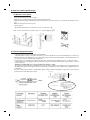
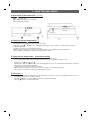
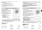
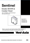
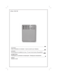
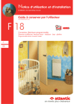
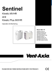
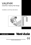
abc
OPAL VAPHMT & VAPHET
PANEL HEATER RANGE
Installation and wiring instructions
230-240V AC ~ 50 Hz
Please read all the instructions carefully in conjunction
with the illustrations before starting the installation.
PLEASE SAVE THESE INSTRUCTIONS
The product you have just purchased has undergone numerous tests and inspections to guarantee the highest quality. Thank
you for your choice and your confidence in us. We hope it will give you entire satisfaction.
Some recommendations
Please read the documentation before starting to install the panel heater.
Disconnect power before working on the panel heater.
Conserve the documentation, even after installation of the panel heater.
Equipment specification (indicated on the label of the device) :
IP24: Equipped protected from water splashes
Class II: Double insulation.
1. 1 - INSTALLATION OF THE PANEL HEATER
1) Where to install the panel heater - This equipment was designed to be installed in a residence. Please ask your distributor before using it for any other
purpose.
- The panel heater should be installed according to normal trade practice and in compliance with legislation in the relevant country (the IEE Wiring Regulations).
- Comply with the minimum clearance distances as indicated in diagram 2 for positioning of the panel heater.
- If your wall covering is laid on foam, a spacer the same thickness as the foam must be placed under the panel heater’s
support. This ensures there is free space behind the panel heater to make sure its control settings are not adversely
affected.
- Do not install the panel heater:
In a draught likely to affect the control settings (under a fan, etc.).
Under a fixed mains power socket.
In volume 1 of bathrooms.
In volume 2 if the controls can be operated by a person using the shower or the bath.
Except in the UK. Please refer to the IEE Regulations 601-06-01 and 601-08-01 (BS7671).
If the panel heater is installed at altitude the air discharge temperature will be increased (by approximately 10°C
per 1000 m of altitude).
2) How to install the panel heater
2.1 Mount the wall support
- Place the attachment lug on the floor 1
- Mark the holes, to determine the position of the lower attachments.
- Raise the attachment lug, making the previously marked holes coincide so that you can locate the remaining two holes
2
- Drill holes and put the inserts into place
- Fix the support.
- Mount the panel heater on mounting S as shown. Lock the lock V. Note : Do not use the device in mobile or feets or on casters (diagram r
-
s
y
2-2) Connecting panel heater
C
- The panel heater must be powered with 220-240V 50Hz
- The panel heater must be connected to the mains by a 2-wire cable (Brown= Phase, Blue=Neutral) via connection box
(Mechanical thermostat : diagram A) ; by a 3-wire cable (Brown= Phase, Blue=Neutral, Black = Pilot wire) by means of a
connection box (version with pilot wire : diagram B)
In humid areas such as bathrooms and kitchens the power socked must be installed at least 25 cm above the floor.
- The installation muse be equipped with an all pole disconnection mechanism with a break contact distance of at least
3 mm in each pole.
- Earthing is prohibited. Do not connect the pilot wire ( black ) to earth.
- The heater must be installed by a qualified electrician in accordance with the local regulations. The heater and the pilot
wire (black) must Not be connected to earth. If the heater wire is damaged, it must be replaced by a qualified person to
avoid hazard.
If a pilot or piloted panel heater is prohibited by 30mA residual current device(RCD), the pilot wire’s power must be
protected by the same RCD as the heater.
Panel heater cable
Phase = brown
Phase
Neutral = blue
Neutral
Electricity
grid
Pilot wire = black
2 possible cases
1st case : only one heater
The pilot wire free end is
insulated and not further connected
2nd case : multiple heaters
The pilot wire of all heaters in a control
group, up to a maximum of 20 units
with any one them used as the
Master, are connected by a
1.0mm2 220-240V
insulated cable
2. USING THE PANEL HEATER
1) Description of the control unit : and V1
/I Switch (0/I)
Temperature adjustment control knob.
Heating indicator light
2) Fixing the comfort temperature :
a) Put the switch to
(marche/ I).
b) Mechanical : set the control knob to between 4 and 5.
Eletronical : set the control knob on 5, the heating indicator V1 comes on if the room temperature is below the
required temperature.
c) Wait for a few hours for the temperature stabilise.
d) If the setting is satisfactory (if necessary use a thermometer to check). Mark the position for future use.
e) If the setting is not satisfactory, adjust it and start again from point c.
3) Fixing the Eco temperature :
(electronic model)
This is the required temperature during periods when the room is unoccupied.
It is recommended that this mode should be used if the room is unoccupied for more than 2 hours.
a) Set the cursor switch knob to .
b) Adjust the control knob between 3 and 4 the heating light V1 comes on, if the ambient temperature is lower than
the instruction of desired Eco temperature.
c) Wait a few hours until the temperature stabilised.
d) If the setting is satisfactory ( if necessary use a thermometer to check). Mark the position.
If the setting is not satisfactory, adjust it and start again from point c.
4) Frost-free : 7
This mode is used keep the temperature at approximately 7°C in the room when you are absent from the house for a
prolonged period (usually more than 24 hours).
a) Leave the switch on I, set the control knob to 7 (mechanical model).
b) Set the switch on 7(electronic model)
5) The heating indicator: V1 (electronic model)
This light comes on when the heating element is working. It may flash when the temperature has stabilised.
6) Locking the controls : and It is possible to look or limit use of the control knob and look the switch to prevent unauthorized manipulation of
the panel heater (children, etc,..)
a) Unhook the panel heater from its wall mounting
b) Remove the slugs P on the back of the thermostat from their mountings
c) Select position B to look the control knob or position L to limit the amount it can be turned. Position N blocks the
switch for Electronic Model.
7) Using the pilot wire
The product with pilot wire can receive the following signal from a master unit :
- COMFORT (Temperature of control knob)
- ECO (Comfort temperature -3°C to 4°C
The product must be connected through the pilot wire to a programming control or a product with Programming cassette in order to use comfort or eco mode. You can thus control several convectors with a single programmer or a
product with programming cassette.
3. RECOMMENDATIONS FOR USE
- There is no point in setting maximum heating the room temperature will not rise any quicker.
- When you air the room disconnect the panel heater by putting the switch to STOP/0
- If you leave for several hours, remember to reduce the temperature
Absence for: less than 2 hours, do not touch the controls
2 to 24 hours, lower the control knob by two graduations.
more than 24 hours or in the summer, put the control knob to (mechanical).
put the switch on (electronic)
- If you have several units in a room, let them operate simultaneously. This will give you a more uniform temperature
without increasing electricity consumption.
WARNINGS
This device is not intended for use by young persons(incliding children) with physical
sensory or mental
disability, or by persons locking experience or knowledge, unless they have received from a person in charge of their safety adequate
supervision or preliminary instructions on how to use the device. Care must be taken
at all times to keep children from paying with the device.
Do not play with the appliance, jean against the front or insert objects or paper in it.
Do not totally or partially block the grilles on the front or inside of the appliance, as
this may cause overheating. If the supply cord is damaged, it must be replaced by a
service agent or similarly qualified person in order to avoid a hazard (applies to units
fitted with a supply cord and plug). Units fitted with a three core supply cord (brown,
blue & black), must be directly connected to fixed wiring by a licensed electrician. All
work on the interior of the appliance must be carried out by a licensed electrician.
MAINTENANCE
To maintain performances of your unit, you should clean the upper and lower grilles of the unit about twice a year using
a vacuum cleaner or a brush.
Have a professional check the inside of the unit every five years.
Dirt may collect on the grille of the unit if the atmosphere is polluted. This phenomenon is due to the poor quality of the
ambient air. In this case, it is recommended to check that the room is well ventilated (ventilation, air inlet, etc;..) and that
the air is clean. The until will not be replaced under the guarantee because of this type of dirt.
The unit casing should be cleaned with a damp cloth, never use abrasive products.
TROUBLE-SHOOTING
If the unit does not heat:
Check that the programmer is in COMFORT mode (electronical).
Make sure that the installation circuit breakers are switched on, or that the load shedder (if you have one) has not
switched off the unit power supply. Check the air temperature in the room.
The unit does not carry out programming orders: (version with pilot wire)
Make sure that the programming unit is being correctly used (refer to its user’s manual) or that the Chronocarte is
properly inserted in its housing and that it is operating normally (batteries?).
The unit is permanently heating:
Make sure that it is not in a draft and that the temperature setting has not been changed.
This unit with electronic control is equipped with a microprocessor that can be disturbed by some severe mains
voltage disturbances (outside EC standards defining the disturbance protection level).
If there are any problems (thermostat blocked, etc.) switch off the unit power supply (fuse, circuit breaker, etc.) for
about 5 minutes to allow the unit to start again.
Have your energy distributor check your power supply if the phenomenon occurs frequently.
WARRANTY CONDITIONS
KEEP THIS DOCUMENT IN A SAFE PLACE
(This certificate should only be produced if you are making a complaint, attached with the invoice of the purchase)
- This guarantee is applicable for 2 years from the date of original purchase and shall be valid for no more than 30 months from
the date of manufacture.
- Your VENT AXIA distributor will exchange parts shown to be defective in manufacture. The replacement parts will be free of
charge but VENT AXIA does not accept responsability for freight or labor charges or losses in transit.
- This guarantee excludes damage by neglect, shipping or accident and any damage due to incorrect installation, use for purposes other than those intended or failure to observe the instructions given..
:
:
CUSTOMER’S NAME AND ADRESS:
•
This information is shown on the plate which can be seen on the left-side or behind the front grille of the unit.
VENT-AXIA with Adress of after-service
12-80-1194
UNIT TYPE *
SERIAL NUMBER *
VENT-AXIA CONTACT NUMBERS
UK NATIONAL SALES CENTRE
Domestic & Commercial
Tele: 01293 530202
Fax: 01293 565169
Industrial
Tele: 01293 441570
Fax: 01293 534898
REPUBLIC OF IRELAND
Vent-Axia Ventilation Ltd.
921 Western Road Industrial Estate
Naas Road, Dublin 12.
Tele: (01) 450 4133
Fax: (01) 450 4570
UK NATIONAL TECHNICAL SUPPORT
Domestic & Commercial
Tele: 01293 526062
Fax: 01293 551188
Internet site at: www.vent-axia.com
Industrial
Tele: 01293 455196
Fax: 01293 455197
Email: [email protected]
The Vent-Axia Guarantee
Applicable only to products installed and used in the United Kingdom. For details of the Guarantee outside of
the United Kingdom contact your local supplier.
Vent-Axia guarantees this product for two years from the date of purchase against faulty material or
workmanship. In the event of any part being found to be defective, the product will be repaired, or at the
Company’s discretion the product will be replaced without charge, provided that the product:
1).
2).
3).
4).
Has been installed and used in accordance with the instruction given with each unit.
The electricity supply complies with the rating label.
Has not been misused, neglected or damaged.
Has not been modified or repaired by any person not authorized to do so by Vent-Axia.
IF CLAIMING UNDER THE TERMS OF THE GUARANTEE
Please return the complete product, carriage paid to your original supplier by post or in person.
Please ensure that it is adequately packed and accompanied by a letter clearly marked ‘Guarantee
Claim’ stating the nature of the fault and providing proof of the date and source of purchase
As part of the policy of continuous product improvement
Vent-Axia reserve the right to alter specifications without notice
Head Office: Fleming Way, Crawley, West Sussex RH10 9YX
Tel: 01293 526062 Fax: 01293 551188
Internet site at: www.vent-axia.com
437169A
0807