1
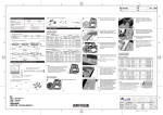
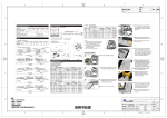
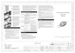
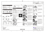
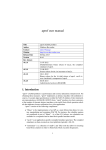
2
1
4
3
修订
版本 标记 处数
内容
V0
A
Cut LED string to achieve
required quantity, and strip the
wires for about 10mm(0.4in).
04
Note: Please cut at the middle of the
wires.
When the wires of the last
module exposed , firstly strip the
wires for about 10mm(0.4in) ,
then cap the “+” wire and the
“-“ wire with the twist-on wire
connectors to protect against
moisture and corrosion.
05
1.Installation notes:
Make sure the polarities of connection made at modules and
power supply are correct, otherwise the sign will not light.
2.Notes for Optional Supplies:
When the standard module quantity per string is 20pcs, it is
recommended to choose the safety-certificated power supply
with 18W rated power and DC 12V output voltage (with
short-circuit, overvoltage and overload protections). Tolerance
range for output voltage of power supply is ±5%. If more
modules are needed, ensure the power supply has more than
20% load allowance.
Malfunction&Solutions Table
B
Malfunctions
Adjust LED modules to the
better place, then fix them with
the screws.
2. The power supply is auto
protected since the short or
open circuit occurs at the
output of the SMPS.
Drill a hole in proper place,
then, run the supply wires
through the hole and fix them
for good protection.
C
Some LED
modules
don't work
09
3. Too many LED modules are
connected.
LEDs are
blinking
A
Do not disassemble or modify the module; Don't touch LED
surface with the sharp stuff.
Don't install the modules with power on.
Forbid using any organic chemical solvents.
Have a licensed electrician install, maintain and serve the
products!
Use the neutral glass glue to fix this products, do not seal the
products until the glue solidified in open environment 4 hours
later.
During installing, please insulate the exposed wires and the
connection points; meanwhile, please treat the wires to protect
against moisture and corrosion.
Please choose 20AWG wires or thicker wires to avoid overload
or other hazard when the supply wires of modules need
extension .
The maximum connectable quantity per string is 20pcs LED
modules. Forbid exceeding! The supply wire between the
module and the power supply should be no longer than
2m(78.7in), or it will cause over-heated or other unwanted
consequences.
This product is applicable to the inside of the light box or
channel letter, forbid exposing it to outdoor or semi-outdoor
environment directly!
Sunrise Series LED Module
Manual
M603AA
B
Declaration
connected to the power supply.
3. Some modules' polarities are
connected reversely.
Brightness of
the LED is dim
or not even
2.The wire loss of power supply
or the wire loss difference
between each branch is too
much.
Note: Drill a hole with proper
strength to avoid damaging the
panel of the channel letter.
Make sure the polarities of the
LED modules are correctly
connected to that of the
power supply.
Remove any short or open
circuits and other
malfunctions, and energize
the fixture.
1. Some SMPS don't get primary
power.
Check the power supply and
remove malfunctions.
2. Some modules are wrongly
1. Power Supply is overloaded.
08
Solutions
3. The input wires of the modules
are connected reversely.
Note: The maximum connectable
quantity per string is not more than
20 modules.
07
Possible Causes
1. There is no primary power.
None LED
works
变更者
WARNING
NOTES
Malfunction & Solutions Table
When the modules need to be
connected, please strip the wires
for about 10mm(0.4in),then connect
the modules with twist-on wire
connectors ( red stripe wire“+” to
red stripe wire “+”, white wire “-“ to
white wire “-“) .
06
日期
N/A
Connect the wires correctly.
Change a power supply with
high power according to the
actual load.
Make sure the working voltage of
each module is within ±5% of
rated voltage (1.shorten the wire
between the power supply and
the first module or use thicker
supply wires; ensure the quantity
run on each branch is not more
than the maximum connectable
quantity, and ensure each branch
has similar module quantity, it will
be better with the quantity
difference within 3 modules).
Adjust the module quantity of
each branch to meet the
maximum connectable quantity.
1 . Loose connections exist.
Find the loose connections
and remove any malfunctions.
2. SMPS doesn't work.
Replace the power supply.
Warranty: 3 years or 13,000 hours, whichever comes first.
During installing, first stick the products into places and then
secure the products with screws after adjusting them well.
If the external flexible cord of this luminaire is damaged, it shall
be exclusively replaced by the manufacturer or his service agent
or a similar qualified person in order to avoid a hazard.
All the data and pictures in this manual are subject to actual
products.
Information provided is subject to change without notice.
C
Read this manual carefully before using this product and keep it!
V1.0
D
备注:
1.尺寸:3 85*210mm;
2.材质:8 0g书纸;
3.公差:±1mm;
4.灰度双面印刷;
5.虚线不印刷,来料必须从虚线处折好;
6.适用型号:M603AA。
说 明 书正面
SHENZHEN RISHANG OPTO-ELECTRONICS CO.,LTD.
零件名称
2
3
旭日系列产品说明书
(英文 无LOGO)
设 计 方艳平 日期
2012.05.23
材 质
表面处理
零件编码
308-01-071
审 核
日期
重 量
图纸编号
RD-M603AA-BZ005
标准化
日期
比 例
日期
单 位
页
1
D
深 圳 市 日 上 光 电 有 限 公 司
数
共 2 张
第 1 张 批 准
FM-WI-7-18-01
N/A
2
1
4
3
修订
版本 标记 处数
内容
V0
A
Installation & Application Examples
Model and Specification
1. Layout Density Guidelines for Light box
Model:
M603AA
Rated Power (W/piece):
0.72
Working Voltage (V):
DC12
IP Grade :
IP65
Operating Temperature (℃[°F]):
-25~60[-13~140]
Storage Temperature (℃[°F]):
-25~70[-13~158]
Depth of Light
Box(mm[in])
Dimension Drawings of Standard Connection
Unit: mm[in]
Dimension Drawings of Single Module
Note: Please cut at the middle of the
wires.
Installation Density
(pcs/m²[pcs/ft 2])
Layout Spacing
(mm[in])
Illuminance
Range(lux)
dz=80[3.2]
dx=90[3.5] dy=50[2.0]
222[21]
6200-7500
dz=100[3.9]
dx=90[3.5] dy=70[2.8]
159[15]
4000-4900
05
dz=120[4.7]
dx=110[4.3] dy=90[3.5]
101[9]
2700-3050
dz=150[5.9]
dx=120 [4.7] dy=110[4.3]
76[7]
1900-2200
dz=180[7.1]
Cut LED string to achieve
required quantity, and strip the
wires for about 10mm(0.4in).
dx=150[5.9] dy=130[5.1]
51[5]
1440-1570
Notes:
1,The above layout data are tested with M603AA-UL-W1
module (Color Temperature: 6000K);
2,Tested in 3mm(0.12in) depth white acrylic board with
54.4% luminous transmittance;
3, All data in the table are minimum illuminance with the
uniform surface illumination;
4,The above data are for reference only.
06
When the wires of the last
module exposed , firstly strip the
wires for about 10mm(0.4in) ,
then cap the “+” wire and the
“-“ wire with the twist-on wire
connectors to protect against
moisture and corrosion.
When the modules need to be
connected, please strip the wires
for about 10mm(0.4in),then connect
the modules with twist-on wire
connectors ( red stripe wire“+” to
red stripe wire “+”, white wire “-“ to
white wire “-“) .
Parts and Tools
Installation Procedures
1. Installation and Connection Illustration:
Power Appearance (Only for reference)
Clean the light box, and then
determine the installation
position and quantity.
01
07
Adjust LED modules to the
better place, then fix them with
the screws.
A
Reference Scheme
Stroke
Width
Thickness
(mm[in])
(mm[in])
A60[2.4]
H60[2.4]
A90[3.5]
H80[3.1]
A110[4.3] H100[3.9]
A140[5.5] H120[4.7]
A150[5.9] H150[5.9]
A180[7.1] H180[7.1]
Modules
Dimension
Area
2
2
Installation
Density
Illuminance
Range
(m [ft ])
(mm[in])
(pcs)
(pcs/m²[pcs/ft ])
(lux)
0.14[1.5]
100[3.9]
14
100[9]
4500-5500
(mm[in])
L473*W290
[L18.6*W11.4]
L710*W430
[L28.0*W16.9]
L855*W525
[L33.7*W20.7]
L1040*W653
[L40.9*W25.7]
Maximum Space Overall
between Modules Quantity
0.3[3.2]
100[3.9]
2
14
47[4]
3600-4100
0.45[4.9]
120[4.7]
22
49[5]
2200-2680
0.68[7.3]
130[5.1]
26
38[4]
2000-2380
150[5.9]
29
34[3]
1940-2200
160[6.3]
33
25[2]
1390-1500
L1194*W710
0.85[9.2]
[L47.0*W28.0]
L1490*W900
1.34[14.4]
[L58.7*W35.4]
Notes:
1,The above layout data are tested with M603AA-UL-W1
module (Color Temperature: 6000K);
2,Tested in 3mm(0.12in) depth white acrylic board with
54.4% luminous transmittance;
3, All data in the table are minimum illuminance with the
uniform surface illumination;
4,The above data are for reference only.
H
Note: The maximum connectable
quantity per string is not more than
20 modules.
变更者
2.Layout Density Guidelines for Channel Letter
Channel Letters
Reference Scheme
Profile
B
04
日期
N/A
B
L
A
W
Installation Procedures
Clean the inside of the channel
letter.
01
Red stripe wire (+)
White wire or
black stripe wire (-)
Wires are connected to
the output of power supply
C
If the modules are packed in a
row with back double-sided
adhesive tape, please divide
them with a knife.
02
2. Product parts and Tools required:
(1) Product Parts
08
M603AA(20pcs)
Cutting Nipper, Electrical
Drill&Drilling Bit
D
Twist-on Wire Connector
(4pcs)
Self –tapping Screw
(ST2.9)
Remove the tape backing and
stick LED modules into places.
03
09
Make sure the polarities of the
LED modules are correctly
connected to that of the power
supply.
C
Note: Don't scratch the module and
the wire.
Remove the tape backing and
stick LED modules into places.
03
Art Knife
备注:
1.尺寸:3 85*210mm;
2.材质:8 0g书纸;
3.公差:±1mm;
4.灰度双面印刷;
5.虚线不印刷,来料必须从虚线处折好;
6.适用型号:M603AA。
说 明 书背面
SHENZHEN RISHANG OPTO-ELECTRONICS CO.,LTD.
零件名称
2
D
深 圳 市 日 上 光 电 有 限 公 司
3
旭日系列产品说明书
(英文 无LOGO)
设 计 方艳平 日期
2012.05.23
材 质
表面处理
零件编码
308-01-071
审 核
日期
重 量
图纸编号
RD-M603AA-BZ005
标准化
日期
比 例
日期
单 位
页
1
If the modules are packed in a
row with back double-sided
adhesive tape, please divide
them with a knife.
02
Note: Drill the hole with proper
strength to avoid damaging the
panel of light box.
Note: Don't scratch the module and
the wire.
(2) Tools required
Drill a hole in proper place,
then, run the supply wires
through the hole and fix them
for good protection.
数
共 2 张
第 2 张 批 准
FM-WI-7-18-01
N/A