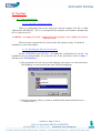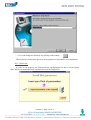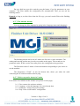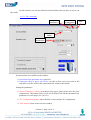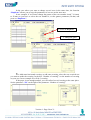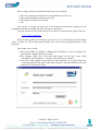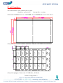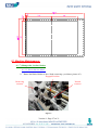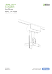
1
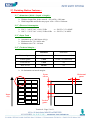
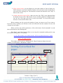
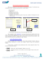
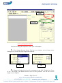
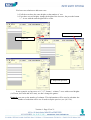
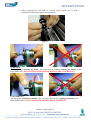
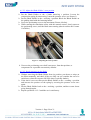
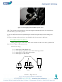
Unité de Façonnage Automatique
Automatic Finishing Station
13" x 19"
eous
/simultan
e
é
n
a
lt
u
tting
En sim
coupe/cu
reasing
rainage/c
ting
n/perfora
o
ti
a
r
fo
r
e
p
User Manual
Version n°4
Janvier/January 2003
Summary :
1°) Finishing Unit Description : _______________________________________________ 3
2°) Finishing Station Features : _______________________________________________ 5
2.1°) Dimensions (With x Depth x Height) : _________________________________________ 5
2.2°) Electrical Consumption : ____________________________________________________ 5
2.3°) Paper Feed : ______________________________________________________________ 5
2.4°) Technical Margins : ________________________________________________________ 5
3°) Running the finishing Station : ____________________________________________ 6
3.1°) Machine controls : _________________________________________________________ 6
3.1.1°) On / Off Button :________________________________________________________________ 6
3.1.2°) Feeder Switch : _________________________________________________________________ 6
3.1.3°) Mode Selection Switch: __________________________________________________________ 6
3.1.4°) Page Start Button: _______________________________________________________________ 6
3.1.5°) Forward / Reverse Switch: ________________________________________________________ 7
3.1.6°) Mechanical Counter Reset: ________________________________________________________ 7
3.1.7°) Serial Port : ____________________________________________________________________ 7
3.1.8°) Contrast Detection Sensor Calibration Button : ________________________________________ 7
3.1.9°) The warming light: ______________________________________________________________ 8
3.2°) Finishing cycle : ___________________________________________________________ 8
3.2.1°) Finishing Cycle Description: ______________________________________________________ 8
3.2.2°) The Feeder: ____________________________________________________________________ 9
3.2.3°) Vertical Finishing Unit : __________________________________________________________ 9
3.2.4°) Evacuation Guides : _____________________________________________________________ 9
3.2.5°) Output Bin: ___________________________________________________________________ 10
3.2.6°) The Scrap Bin : ________________________________________________________________ 10
4°) The Pilot: _____________________________________________________________ 11
4.1°) Pilot installation:__________________________________________________________ 11
4.1.1°) Upgrade a previous version: ______________________________________________________ 11
4.1.2°) Installing the Pilot for the first time: ________________________________________________ 11
4.2°) First use: ________________________________________________________________ 12
4.3°) The welcome window: _____________________________________________________ 13
4.4°) “With crop marks detection” mode:__________________________________________ 13
4.4.1°) The commands:________________________________________________________________ 14
4.4.2°) The windows accessible from the “With crop marks detection” mode: _____________________ 15
4.5°) “Without crop marks detection” mode: _______________________________________ 17
4.5.1°) The template opening window:____________________________________________________ 17
4.5.2°) The “Send commands” window:___________________________________________________ 18
4.5.3°) The parametric window: _________________________________________________________ 20
4.5.4°) Create/change a template: ________________________________________________________ 21
4.5.5°) Save a template: _______________________________________________________________ 25
5°) Job Templates :_________________________________________________________ 26
6°) Machine Maintenance : __________________________________________________ 27
6.1°) Change the circular blades: _________________________________________________ 27
6.1.1°) Put on the new blade: ___________________________________________________________ 27
Version 4 - Page 1 on 31
6.1.2°) Adjust the Blade Holder’s arm position _____________________________________________ 29
6.1.3°) Set the pressure on the blade______________________________________________________ 29
6.2°) Sheet Detection Sensor :____________________________________________________ 30
Version 4 - Page 2 on 31
1°) Finishing Unit Description :
Access to the
circular blades
Output Bin
Power Plug
PC plug
Access to the scrap bin
Photo 1
Page counter
(number of sheet cut)
Forward/Reverse
(manual mode)
Page start
button
Automatic / Manual
1
/
0
Photo 2
Version 4 - Page 3 on 31
Feeder tray
remote
button
Rails button
Photo 3
Contrast Detection
Sensor
Calibration button for
Contrast Detection
Sensor
Photo 4
Version 4 - Page 4 on 31
2°) Finishing Station Features :
2.1°) Dimensions (With x Depth x Height) :
Ø Without Output Bin, feeder stowed : 650 x 850 x 1260 mm.
Ø With Output Bin and feeder tray open : 650 x 1520 x 1260 mm.
2.2°) Electrical Consumption :
Ø 220 V – 240 V VAC ±10%, 50 Hz
⇒ 500 VA, 2.3 A MAX.
Ø 100 V – 120 V VAC ±10%, 50 Hz-60 Hz ⇒ 500 VA, 5 A MAX.
2.3°) Paper Feed :
Ø Automatic up to 2,000 sheets (80 g).
Ø Maximum size 330 * 482,6 mm.
Ø Minimum size 170 * 190 mm.
2.4°) Technical Margins :
Minimum
Maximum
Horizontal gutter
5 mm
14 mm (recommended)
Vertical gutter
5 mm
10 mm (recommended)
Front off cut
5 mm
NS
Rear off cut
40 mm
NS
Ø No limitations on lateral margins
Front
off cut
Paper
way
Vertical
gutter
Version 4 - Page 5 on 31
Horizontal
gutter
3°) Running the finishing Station :
3.1°) Machine controls :
9 button, switch or plugs are available on the machine :
Ø
Ø
Ø
Ø
Ø
Ø
Ø
Ø
Ø
On / Off button with power supply : on the left side of the machine.
Up / Down feeder switch on the front of the machine.
Page start button : on the top of the machine
Warming light : below the Page start button
Mode Selection Switch : below the warning light
Forward / Reverse (in manual mode) : below the Mode Selection Switch
Page Counter Reset
Serial Port : to connect the machine to the computer where the pilot is installed
Contrast Detection Sensor calibration Button
3.1.1°) On / Off Button :
This button (see picture n°1) is used to switch the machine on or off. It’s placed above
the electrical plug.
Remark : Between the plug and the button, you can find the place for fuses. The default
configuration for the fuses is 6,3 A retarded, 250 VAC, 5*20.
3.1.2°) Feeder Switch :
Press the top (bottom) of the switch to make the tray move up (down). To stop the
tray, press the bottom (top) of the switch.
Caution : be careful the tray isn’t stowed before rising it
3.1.3°) Mode Selection Switch:
You have the choice between 2 modes : automatic or manual. The manual one allows
you to make your tool adjustment.
Ø To choose the automatic mode, place the switch into position 1
Ø To choose the manual mode, place the switch into position 0.
Remark : if you have worked in manual mode, don’t forget to commute the switch into the
automatic mode to make your jobs.
3.1.4°) Page Start Button:
This button is used to feed the paper whether in manual or automatic mode in manual
mode, the page will stop after the first feeding rollers.
Version 4 - Page 6 on 31
3.1.5°) Forward / Reverse Switch:
This button is available in manual mode only to have the paper to go forward or
backward.
3.1.6°) Mechanical Counter Reset:
The counter shows you how many pages you have cut. To reset this counter, you shall
press the small black button.
3.1.7°) Serial Port :
A pilot installed on a PC drives the finishing station, threw a serial port connection.
3.1.8°) Contrast Detection Sensor Calibration Button :
3.1.8.1°) The Sensor :
The Contrast Detection Sensor (CDS) is used to detect some cutting crop mark (line)
or creasing crop mark. These crop marks must be placed like describe below :
Ø All the mark must be printed in monochrome black for the “crop
mark mode”
Ø Crop mark length : 8 mm minimum
Ø Position on the paper sheet : between 0 and 12 mm from the side of the sheet
Ø The crop mark must be centred on the cutting and creasing position
Ø To cut : a 0,5 point thick line
Ø To crease : a 4 points thick line
Between 0 and 12 mm
Cutting or creasing position
8 mm minimum
Left side of the sheet
3.1.8.2°) The calibration :
It may happen that the sensor loses its sensibility after a certain time. In this case, it’s
recommended to clean the sensor (see the chapter on the machine maintenance). If the crop
marks or always badly detected, it’s necessary to recalibrate the sensor.
This calibration must be done with a sheet on witch a crop mark is printed. The
calibration consists to note the difference between the paper color and the crop mark color.
The calibration need two steps :
Version 4 - Page 7 on 31
1°) Sheet color detection : on a no printed area (without a crop mark)
2°) Crop mark color detection
Follow the operations below to do the calibration :
1°)Print a sheet of paper with some 0,5 points thick lines
2°) Sheet color detection :
a) Switch the machine into manual mode on the machine panel.
b) Bring the sheet of paper under the CDS (careful : the crop mark mustn’t be under
the spotlight.
c) Press the CDS calibration button until the red spotlight of the sensor flash.
3°) Detection of the contrast between the crop mark and the sheet color :
d)
e)
f)
g)
Put the crop mark under the red flash spotlight.
The crop mark must be centred on the light.
When the crop mark is in position, press the CDS calibration button as before.
The calibration is successful if the light stop to flash.
Now the calibration is finished
Remark : If the light flash more quickly after the calibration (step d to g), the calibration have
failed. It’s recommended to shut down the power during 10 seconds and then to
recalibrate the sensor.
3.1.9°) The warming light:
3 warming light are available on the machine panel :
Red LED : Continuous light ⇒ there’s a jam inside the machine
Flashing light ⇒ Misfeed, the sheet didn’t leave the feeder
Orange LED : Continuous light ⇒ the machine is in manual mode
Flashing light ⇒ the CDS calibration is running
Green LED : Continuous light ⇒ normal condition of work
3.2°) Finishing cycle :
3.2.1°) Finishing Cycle Description:
The pages are fed by an automatic feeder, then they pass through several finishing
tools :
Ø A vertical finishing unit made of :
• A first set made of 4 vertical finishing tools
• A second set made of 4 vertical finishing tools
Version 4 - Page 8 on 31
Ø A horizontal creasing unit.
Ø A horizontal cutting unit.
With the second set it is possible to place some evacuation guides to evacuate vertical
paper scraps.
3.2.2°) The Feeder:
Ø
Ø
Ø
Ø
Ø
Use the up / down button to make the tray move down.
Put some paper into the feeder
Move the tray up (be careful : the tray isn’t folded away)
When the paper is close to the feeding roller, use the handle of the feeder to
Align the paper pile.
Remark : to guide the paper correctly, the paper pile should be
straightly vertical and the paper itself shall be correctly cut.
3.2.3°) Vertical Finishing Unit :
It consists in a rod with 4 blades holder fitted on. These blade holders can rotate
around the rod and take 3 position.
Ø Engaged
Ø Neutral
Ø Blade removing position
Important : in neutral position or blade removing position, the locking screwed
mustn’t be screw.
To make the adjustment of these tools easier, it’s better to use a page on witch he
cutting lines are printed.
To adjust the position of the blade holders from the rest position :
Ø Rotate the blades holders into engage position. In that position the fixation
screws must be above the groove on the guiding axis.
Ø Move the blades holders to place the blades upon the cutting marks on the page
Ø Place the circular blades on contact with the counter cut roller
3.2.4°) Evacuation Guides :
When the circular blades are in position, place the evacuation guides close to them.
There is one evacuation guide for the right outer cut, one for the left outer cut.
All the vertical paper scraps will be sent to the scrap bin.
Version 4 - Page 9 on 31
3.2.5°) Output Bin:
After being cut, the cards are sent to the output bin. If you have used the evacuation
guides, you won’t find any scraps in this bin.
3.2.6°) The Scrap Bin :
A scrap bin is placed under the machine to collect the scrap generated by the cut.
To empty this bin, open the rear door.
Caution : empty the bin if the lenghtwise off cuts remain stucked below the
evacuations guides.
Version 4 - Page 10 on 31
4°) The Pilot:
4.1°) Pilot installation:
4.1.1°) Upgrade a previous version:
There’s a configuration file on the disk given with the machine. The file is called
“MassicotA3-XXXXX.ini”. The 5 X correspond to the machine serial number. Rename this
file in “MassicotA3.ini”.
CAREFUL: according to you PC configuration, the extension “.ini” could be not shown
on your screen.
When you have renamed the file, protected the disk against writing. To finish the
installation, see the next chapter.
4.1.2°) Installing the Pilot for the first time:
Put the CD-ROM in your CD drive. According the configuration of your PC, the
installation can start automatically. If it is not the case, in the start menu, click on “Run…”
and then write “D:\Install.exe”.
Ø The programme will ask you in witch language you want to see the instructions.
This language is not necessarily the same as the pilot language:
Ø Select the directory where you want to install the Pilot (the default directory is
“C:\MassicotA3”).
Version 4 - Page 11 on 31
Ø You can change the directory by clicking on the button:
Then follow the instructions given by the programme to personalise your installation.
4.2°) First use:
In order to run properly, the Pilot needs the configuration file that is on the floppy
disk. When you launch the Pilot, a window ask you the floppy disk:
Version 4 - Page 12 on 31
Put your disk into your drive unit the press the button “Copy the parameters on your
computer”. The Pilot installs the configuration file automatically. Then you can run the
finishing station.
Remark: as long as you don’t have done the file copy, you can’t run the Pilot or the finishing
station.
4.3°) The welcome window:
You can change the Pilot language by going in the Language menu and changing it.
The finishing station can be run in 2 modes: the first one is 100% automatic. The
cutting and creasing position are given by crop marks on the paper. The second one is a
parametric mode. In this case the user must precise the cutting and scoring positions.
The Pilot shows these 2 modes: click on the button corresponding to your choice to
use the machine.
The information “COM1”, on the left bottom side, shows you where the cable
connecting the PC and the machine must be plug.
4.4°) “With crop marks detection” mode:
Four menus are available on this window (see picture on next page):
Ø
Ø
Ø
Ø
1 - Exit: return to the welcome window
2 - Language : select the language if it is not already done
3 - Parameters : change the several settings
4 - Help : Pilot version and PC configuration
Version 4 - Page 13 on 31
On this window you can also find the marks thickness that you have to use to run
this mode.
4.4.1°) The commands:
Papers
Parameters
PC
Configuration
Paper
Choice
Counter
(de)activation
Several options are available on the window:
Ø Activation of the pneumatic tray (optional)
Ø Cutting the sheet of paper rear off cut: in order to have only your cards in the
output bin (careful, activate this option make the cadences decreased)
Setting the parameters:
Ø “Papers Parameters” button: according to their types, papers don’t have the same
comportment. This button allows you to set the Extra-Feed and the pneumatic tray
parameters for each paper (see § 4.4.2.1).
Ø “PC Configuration” button: shows the Pilot version and the PC configuration
Ø “Exit” button: return to the welcome window
Version 4 - Page 14 on 31
Exit
Ø «Page count» button: you can display on screen the number of sheet of paper cut.
If this function is activated, the Pilot window will come back on the foreground of
your screen for each page cut. This function is deactivated when the icon “Stop” is
show on the screen.
Ø Contrast detection sensor offset: when you move the CDS, it may happened that
the distance between the CDS and the creaser (and the guillotine) changed. In this
case the cut of the page will not be on the crop marks. To correct this trouble,
increase or decrease the offset value.
Before starting your job, precise the number of page you want to cut. If you want to
know how many exposure you will have at the end of the job enter the numbers of rows and
columns on your pages.
When you have enter all the parameters, click on the button “Send commands” to send
these information to the finishing unit.
The “Pause” and “Stop” buttons allow you to stop the commands sending and to stop
the machine during while it is running.
4.4.2°) The windows accessible from the “With crop marks detection” mode:
4.4.2.1°) The paper window:
The window can be open by clicking on the “Paper Parameters button the main
window or via the menu: “Parameters \ Papers”.
Delay between
two pages
Paper
name
Extra-feed
Sucking time
(in s)
Version 4 - Page 15 on 31
Blowing time
(in s)
Ø Remove a paper from the list: click on the cell on the left of the paper name then
click on the button “Delete”. You must delete the paper one by one.
Ø Add a paper to the list: double-click on a paper name cell. Give a name for the
new paper and go to the next cell with the tabulation key.
The 4 parameters require correspond to the following physical properties:
Ø “Extra-Feed” correspond to the paper advance given by the pick up rollers to feed
the paper to the registration roller.
Ø “Sucking UP” and “Blowing up” are need if you used the pneumatic tray. The
paper is sucked during X seconds. During this time the tray blow between the
page and the net one to pull one from the other
Ø “Tempo” correspond to the delay between each sheet of paper
4.4.2.2°) The “General setting” window:
This window can be open via the menu “Parameters \General settings”.
This window allow you to set 4 parameters:
Ø Chose the serial port to connect the machine (if you disagree with the computer)
Ø Set the ejection of the rear of cut not to find it in the output bin
Version 4 - Page 16 on 31
Ø If you have a stretch during the printing, you can enter this stretch and the
computer will automatically calculate the new position of your exposure
Ø Activation of the pneumatic tray on by default)
4.4.2.3°) The “factory” parameters windows:
Accessible by the menu “Parameter \ Factory”. We advice you against any
modification of any parameters of the windows without the instruction of a M.G.I.
Technician. These parameters set the machine working.
4.5°) “Without crop marks detection” mode:
On the welcome page, as for the “With crop marks detection” mode, you can select le
“Without crop mark detection” mode.
If you have selected this mode, the template opening window will be opened.
4.5.1°) The template opening window:
7 - New
template
1 - The explorer
3 - Template
preview
2 - Templates
list
4 - Search in the
subdirectories
5 - Open a
template
6 - Delete a
template
8 - Return to the
welcome page
This window allow you to choose a saved template. Three different zone appear:
Ø The explorer: to find the folder where your template is saved (1)
Ø The template list of the current folder (2)
Ø A preview of the selected template (3)
Version 4 - Page 17 on 31
In order to limit the exploration operations, you can, by selecting “directories” (4),
show the templates that are in the subdirectories of the selected directory. A folder
“Template” is create in the Pilot directory during the installation.
Several buttons allow you to open (5), delete (6) or create (7) a template.
A click on the button “OK” lead you to the “Send commands” window. A click on
“New template” will lead you to the “Parametric window”. And to finish, a click on the
button “Cancel” (8) will make you return to the welcome page.
4.5.2°) The “Send commands” window:
Zone n°1
Zone n°2
Zone n°3
Zone n°4
4 distinct zones are visible on this window:
Ø
Ø
Ø
Ø
1 - The menus
2 - The function buttons
3 - The template preview
4 - Parameters selection zone
Version 4 - Page 18 on 31
4.5.2.1°) “Send commands” window menus:
Here you can find the same menus that in the “With crop arks detection” mode
window. The “File” menu is added. With this menu you can:
Ø
Ø
Ø
Ø
Create a new template
Open an already existing template
Save a template
Save a template as a new template
4.5.2.2°) “Send Commands” window function buttons:
Ø
: New template: leads you to the Parametric windows (§ 4.5.3)
Ø
: Open a template : show the template opening window (§ 4.5.1)
Ø
: Save the current template
Ø
: Save the current template under another name and/or in another folder
Ø
: Change the preview scale
Ø
: Open the parametric window for the current template (§ 4.5.3)
Ø
: Open the paper window (§ 4.4.2.1)
Ø
: Open the General settings window (§ 4.4.2.2)
Ø
: Display the cutting and creasing positions for the current template
Ø
: Open the “About” window (§ 4.4.1)
Ø
: Back to the welcome page
4.5.2.3°) Current template preview:
When a template is open, on the right of the screen appear:
Ø The template format
Ø Template description
Ø Cutting and creasing positions preview. You can see the distances between
operations by pressing the button “Info”
To change cutting and creasing parameters, see the chapter about template
creation (§ 4.5.4).
Version 4 - Page 19 on 31
4.5.2.4°) Send the parameters to the machine:
The zone n°4 correspond to the machine communications buttons. You find the same
commands as in the “With crop marks detection” mode window:
Ø
Ø
Ø
Ø
Ø
Ø
The paper type
Page count
Number of sheet to cut
Pneumatic tray activation
Cutting the “Rear of cut”
Number of cards calculation system: if you enter a number of columns, the screen
will be slip up.
Separation
Preview with 1
column
Preview with 2
columns
Ø The machine command buttons: Send commands, Pause, Stop
One command is add: ‘Top detect”. If you use this option, thr machine will use the
CDS to find the first crop mark on the sheet. The Pilot will use this mark as reference. The
other programmed operations (cutting and creasing) will be moved from this mark. This
option is useful when the top a printing has a huge variation.
4.5.3°) The parametric window:
When you double click on the preview of the “Send commands” window, when you
press the button “Parameters” or on the “New template” button, you go to the “parametric
window”.
In this window, you find the menus and buttons of the “Send command” window. Two
buttons are add on the window:
Ø
: Back to the “Send Commands” window (see § 4.3.2)
Ø
:
Send the parameters to the machine to test the template. Only one sheet will
be cut.
Version 4 - Page 20 on 31
You will note that the parameter “Extra-Feed” has been added under the case paper, in
order to set it in this window.
In the red rectangular, you have all the elements to create or change a template
(see § 4.5.4).
4.5.4°) Create/change a template:
4.5.4.1°) Default template presentation:
Here we will see in the sane time how to create and how to change a template. Indeed,
the operations are the same in both cases. To create a new template, press on a button “New
template” present on the “Send commands” and “Opening file” windows.
The default template is the next one:
Ø
Ø
Ø
Ø
Format A3++ (13” x 19” or 482,6 x 330.2 mm)
First cut at 10 mm from the top of the sheet
A second cut at 55 mm from the first
“Cutting Rear of Cut” and “Cutting the front of cut” deactivate.
Version 4 - Page 21 on 31
1 - Format
setting
2 - Number of
row setting
4.5.4.2°) Changing the template:
You have to change the template to create your own template.
1 - First, change the paper format. You have two solutions: select a format in the
folding list (A) or enter the paper length and width (B).
(A)
(B)
2 - Change the height of the front of cut and gutter in the field “”Height” and “Front
of cut”. The height is the distance between two cut f the guillotine. You can have several
height on your template.
Version 4 - Page 22 on 31
You have two solutions to add some rows:
Ø If all the rows have the same height: set the number of row
Ø If you have several heights: change the height of the last row, the press the button
“+”. A row with the same height will be create.
2 - Add some rows
1 - Change the height of the
active row
3 - Repeat the operation
In our example, we have now a 11”*17” format, 1 column, 7 rows with several heights
(1x55 mm, 4x25 mm and 2x55 mm), we don’t change the gutters.
Remark: you can set the number of columns. This information will be used to calculate the
number of cards that will be cut. It used to slip the preview (see § 4.5.2.4).
Version 4 - Page 23 on 31
In the case where you want to change several rows in the same time, the function
“Duplicate” allows you to copy the parameters of one row on the next ones.
In our example, if we want to change the gutters of the rows number 6 and 7 (10 mm)
to 20 mm we just have to select the row number 6, set the gutters parameter (20 mm) and
press on “Duplicate”.
2 - Press on “Duplicate”
1 - Change the gutter
3 - Add some horizontal creasing: to add some creasing, select the row on witch one
you want to make the creasing. In the box “Number of creasing” set the number of creasing
on your row. In our example we will do 3 creasing.
If the paper is not enough marked, you can realised several creasing at the same place.
Set the parameter “N#” on the right of the parameter “Number of creasing”.
Version 4 - Page 24 on 31
The creasing positions are defined from the previous operation:
Ø
Ø
Ø
Ø
The first creasing in relation to the first guillotine cut of the row
The second creasing in relation to the first
The third in relation to the second
Etc..
You can do 8 creasing on each row. If the distances between the creasing are not
compatible with the row height, the Pilot refused to create them.
You can activate the cut of the front of cut in order to evacuate all the scrap in the bin.
4.5.5°) Save a template:
When you have finish your template, you can save it. To do that press one the button
“Save” or “Save as”. The saving window will be open. You can also open this window via the
file menu.
This window has 3 fields:
Ø The saving folder (by default “C:\MassicotA3\Templates”): you can change it by
pressing the “Change Directory” button”
Ø The template label: this is the label that appear on the top of the “Send
Commands” and “Parametric” windows when you open a template.
Ø The name of the template: name and label can be the same. If you tick off the box
“Copy automatically the mane of file into the label” each label different from the
name will be erase by the name.
Version 4 - Page 25 on 31
5°) Job Templates :
You will find below some common jobs. Legend :
dotted line = printed area
interrupt line = creasing
• Imposition cards US (55*91) in an A3 NOBI sheet with full bleed (21 cars in the sheet)
• Imposition for a scored A4 folder with tabs (2 folds) on an A3 NOBI sheet, full bleed :
• Imposition 4 pages (1 fold) on an A3 NOBI sheet, full bleed :
Version 4 - Page 26 on 31
6°) Machine Maintenance :
6.1°) Change the circular blades:
6.1.1°) Put on the new blade:
Ø
Rotate the Blade Holder to the « blade removing » positions (picture #3).
Engaged Position
Removing
Position
Neutral
Position
Figure 1 :
Version 4 - Page 27 on 31
Ø When removing the old blade, be careful always make sure to pull it
symmetrically from the support axis (photo #2)
Figure 2
SCREWING :
The nut spring is hold by the brake. The unscrewing is done by rotating the button of the
blade holder axis. DO NOT HOLD THE HANDLE DURING THE UNSCREWING.
UNSCREWING :
The nut spring is hold by its handle. The screwing is done by the rotating the button of the
blade holders axis. DO NOT HOLD THE BRAKE WHILE SCREWING.
Version 4 - Page 28 on 31
6.1.2°) Adjust the Blade Holder’s arm position
Ø Put the Blade Holder to the « blade removing » position. Loosen the
compression spring by unscrewing 3 turns the pressure screw (see Picture 3).
Ø Put the Blade Holder to the « working » position. Block the Blade Holder on
the guiding shaft with the fastening button.
Ø Screw the positioning screw to the maximum (Picture 4 below).
Ø While rotating the translation rollers with the manual control, slowly unscrew
the positioning screw, until the blade starts turning (then it touches the Counter
Cut Roller).
Figure 3 : Adjusting the arm’s position
Ø Unscrew the positioning screw half a turn more, from that position, to
compensate for a possible concentricity defaults
6.1.3°) Set the pressure on the blade
Ø Without removing the Blade Holder from its position, put sheets or strips on
the Slitter manually, and check if they are fully cut (we consider the cut to be
satisfactory when the cut parts fall if the sheet is quickly shaken).
Ø If the sheet is not cut, then put the Blade Holder to the « working » position
and increase the pressure on the spring by screwing the pressure screw once
again.
Ø Put the Blade Holder back to the « working » position, and have some sheets
going through again.
Ø Repeat operations #1-2-3 until the cut is satisfactory.
Version 4 - Page 29 on 31
Figure 4 : Increasing the pressure with the pressure screw
NB : If the cutting is not satisfactory when reaching the maximum pressure (be careful not to
block the blade), proceed as follows :
a) unscrew half a turn more the positioning screw and start again the pressure setting from
zero.
b) If the no change is observed, try a new blade for the first one may be defective.
6.2°) Sheet Detection Sensor :
Cutting some paper create some dust. Some trouble on the cut can be generated if
there is a lot of dust on the sensor mirror.
4 sensors are using :
Ø
Ø
Ø
Ø
1 sensor type1 at the feeder exit.
1 sensor type 2 at the feeder exit to detect the tray position.
1 sensor type 3 (CDS) before the creaser.
1 sensor type 1 on the creaser
Faces to clean
Type 1
Type 2
Version 4 - Page 30 on 31
Type 3
To prevent these troubles, we recommended you to clean the sensor :
Ø Sensor type 1 and 2 : with a piece of rag (with alcohol if the sensor is greasy)
Ø Sensor type 3 (CDS) : With a dry and soft piece of rag (without alcohol or
water)
Version 4 - Page 31 on 31