1
GSM Direct
GSM Alarm
Smart Power Switch
User Manual
GSM ALARM
SMART POWER SWITCH
User Manual
TABLE OF CONTENTS
Safety Instructions .................................................................................................................................... 3
1
Description and Operation ............................................................................................................ 4
1.1
Purpose and Function .............................................................................................................. 4
1.2
Device Package Contents ....................................................................................................... 4
1.3
External View ........................................................................................................................... 4
1.4
The Device and its Operation .................................................................................................. 5
1.5
Control commands from a telephone ...................................................................................... 7
1.6
Arming and Disarming the Device ........................................................................................... 8
1.7
Turning the Line Load On/Off .................................................................................................. 8
1.8
Panic Button............................................................................................................................. 9
2
Technical Specifications ................................................................................................................ 9
3
Alarm Sensors, Detectors & Annunciators .................................................................................. 10
3.1
Motion Detector MD101 ......................................................................................................... 10
3.2
Door/Window Sensor Switch DWS102.................................................................................. 13
3.3
Alarm Siren SN1-A................................................................................................................. 16
4
Set-up Procedure ........................................................................................................................ 17
4.1
Preparing the Device for Operation ....................................................................................... 17
4.2
Setting Up the GSM Smart Power Switch ........................................................... 17
4.3
Accessing Programming Mode .............................................................................................. 19
4.4
Erasing the Telephone Book (Creating the Default Template) ............................................. 20
4.5
Initial Programming (Set-Up) ................................................................................................. 20
4.6
Changing the Value Parameters............................................................................................ 21
4.7
Adding Notification Telephone Numbers ............................................................................... 21
4.8
Deleting Notification Telephone Numbers ............................................................................. 21
4.9
Adding the Wireless Siren ..................................................................................................... 22
4.10 Deleting the Wireless Siren ................................................................................................... 22
4.11 Adding a Keychain Remote Control ...................................................................................... 22
4.12 Deleting a Keychain Remote Control .................................................................................... 22
4.13 Adding Alarm Sensors & Motion Detectors ........................................................................... 22
4.14 Deleting Alarm Sensors & Motion Detectors ......................................................................... 23
4.15 Changing the Password ......................................................................................................... 23
5
Warranty Coverage...................................................................................................................... 23
2
Safety Instructions
The "GSM Smart Power Switch" (further referred to as GSM Power Switch) meets, satisfies and
exceeds all technical standards and safety requirements. However, as the manufacturer, we would like
to share certain safety precautions with you. In order for you to get many years of operation and to
receive warranty service, please observe the following suggestions.
Do not plug in electric devices whose power requirements exceed allowable levels for
wiring, outlets and the GSM Power Switch.
Do not install the device in locations having a high concentration of water vapors or at a
location with inadequate ventilation (these conditions might create dangerous electrical
conditions). The device is not water-proof; do not expose the device to aggressive
environmental conditions (e.g. rain, leaking liquids, etc.).
Do not install the device at locations near dangerous explosive substances.
Do not install the device at medical facilities. The radio signals emitted by the device might
interfere with the operation of certain sensitive equipment causing a possible threat and
danger to human life.
Do not install the device at locations where mobile telephone usage is prohibited.
Install the battery with proper polarity and only when the device is un-plugged and
disconnected from electrical current.
Do not disassemble or attempt to repair the device on your own. In the event of a
malfunction, please contact the service center.
Do not plug-in or attach devices that have damaged electrical plugs.
Do not short circuit the contacts on the device.
Do not touch the electrical outlet in the device with metal objects, your hands and/ or your
fingers.
Do not expose the device to violent shaking and do not drop the device as this may
damage the device.
Store the device with its accessories at a location inaccessible to children.
Attention! The manufacturer is not liable for any damages stemming from improper installation
and use of the device or for any losses caused by not following the provided instructions.
3
1
DESCRIPTION AND OPERATION
1.1
Purpose and Function
The “GSM Smart Power Switch” (further referred to as GSM Power Switch) was designed to
manage alarm sensors via radio channel and to communicate with the user via dialed out phone calls
and/or SMS notifications to a GSM standard mobile telephone. In addition, to remotely turn On/Off
external electrical devices.
To prevent penetration of a secure zone utilizing various wireless alarm sensors together with a
sound and flashing strobe light deterrent, such as the wireless SN1-A siren (sold separately).
The GSM Power Switch operates on 90-250 V current 50/60 Hz and is capable of switching a line
load On/Off not in excess of 16 A.
In the event of a power failure, the GSM Power Switch contains a CR 123A lithium battery backup power source. The back-up battery power source does not allow for remote line load operation,
but does maintain and support protective security functions.
The device uses a grounded three prong plug.
1.2
Device Package Contents
Chart 1- GSM Power Switch package contents
Description
GSM Power Socket PS100
Keychain Remote Control BN-3S
Motion Detector MD101
Door/ Window Sensor Switch DWS102
User’s Manual
1.3
Quantity
1
1
3
1
1
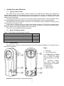
External View
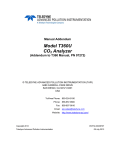
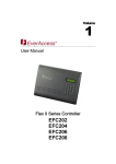
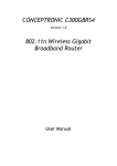
The GSM Power Switch is a security device with line load switch capability. The external view is
described in diagram 1.
Diag.1
1 – Wall plug;
2 – Socket with ground;
3 – Button “R” is used to
enter programming mode
and to create the default
settings template on the SIM
card;
4 – Indicators: “ZONE”Zone status, “LINK”- GSM
network status & “POWER”line load status;
5 – SIM card slot;
6 – Battery holder.
Caution! Install the battery using proper polarity.
4
1.4
The Device and its Operation
1.4.1 Main functions of the “GSM Smart Power Switch”
Dial-up “On/ Off” switching of 110-220V 50/60 Hz line loads not exceeding 16 A;
Transmits device status, including add-ons, to a registered telephone numbers using SMS
notifications;
Network power management via SMS status notifications
Management and control via SMS notifications;
Management via a three button Keychain Remote Control;
Supports light and sound status indicators, main power status, status of add-on devices
(Alarm);
Capable of connecting to a wire-less siren;
Capable of connecting up to six (6) wireless alarm sensors;
Keychain Remote Control provisioned to operate as a panic button;
Transfers to CR123A 3 V battery back-up power during main power failure and maintains
security protection functionality(dial-inline load switching will not operate);
Change settings with the assistance of a mobile telephone, online service http://service.alphasafe.com or iOS/ Android “GSM Power Switch” apps;
Manual or automatic SIM card remaining balance inquiry.
1.4.2 Main functions of the Keychain Remote Control
Buttons on the Keychain Remote Control, by default, execute the following operations:
Button “A”- Arms the device;
Button “B”- Disarms the device;
Button “F”- Turns the device voltage line load On/Off.
The Keychain Remote Control can be programmed to operate as a “Panic” button device.
Button “A”- “Panic” button;
Button “B”- Arms/Disarms the device;
Button “F”- Turns the device voltage line load On/Off.
In order to change the KRC operating mode, it is necessary to adjust the parameter value (see
chart 16, cell 33).
For example:
Keychain Remote Controls can be registered to the Device. By default, all the KRC’s are set to a
value of “0”- A Arm/ B Disarm (cell value 33)000000 and in order to convert KRC No.3 button A into
“Panic” button mode, it would be necessary to send the registered Power Switch the following SMS
message: 33)001000- as a result KRC’s 1,2,4,5&6 Button “A” Arms and KRC No.3 Button “A” is set to
function as a “Panic” Button.
1.4.3 Indicators on the Keychain Remote Control and GSM Power Switch
The GSM Power Switch is outfitted with light and sound indicators.
The “ZONE” light diode indicates security functions; the “LINK” light diode indicates GSM network
state; the “POWER” light diode indicates power line load status (On/Off).
The Keychain Remote light diode indicates Armed, dis-armed, line load On/Off. A status indicator
description is provided in charts 2-4.
5
Chart 2- Keychain Remote Control and GSM Power Switch Indicators
Event/ Mode
PS “ZONE” Diode Indicator
PS Sound Indicator
KRC diode Indicator
Battery Power On
GSM Network Search
Entering Prog. Mode
―
Glows Orange
Glows Orange
KRC Link-up
Glows Orange
1 audio chirp
―
3 audio chirps
1 extended audio
beep
Arming
Flashes Green During Arming
Disarming
―
Short flashes green during 12
sec. when powered Via battery
and steadily glows green when
plugged into AC main power
1 audio chirp
―
―
―
Alternately flashes
Red/ Green
Briefly glows Red
by a series of audio
beeps While arming
Briefly glows Green
―
―
Flashes Green
―
―
Flashes Red
Series of audio
beeps
―
Standby Mode
Attention
Alarm
1 audio beep
followed
Chart 3- “LINK” Light Diode Indicator
“LINK” Light Diode Indicator
Power Source
Indicates Signal Strength (Continuously Glows Green- Good, OrangeMedium & Red- Poor)
―
On Main AC Power
On Battery Power
Chart 4- “POWER” Light Diode Indicator
“POWER” Light Diode Indicator
Power Source
On Main AC Power
Load on
Load off
On Battery Power
Glows Red
Glows Green
Flashes Red @ 12 sec. intervals when in Disarmed mode
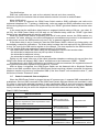
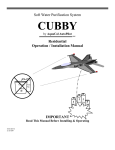
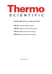
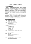
1.4.4 Notifications
The GSM Power Switch transmits SMS status notifications to the telephone numbers stored in the
SIM card memory indicating Alarm, Armed/ Disarmed, presence or absence of power, etc. (samples,
as seen in diag. 2-4).
Armed by RC#1
Diag.2 SMS “Armed”
Disarmed by RC#1
Diag.3 SMS “Disarmed”
Alarm
Diag.4 SMS “Alarm”
6
Test Notifications
SMS test notifications are sent at the selected interval and show remaining balance. The time
reference point for the selected interval starts when the device is turned on and activated.
Alarm Notifications
When an alarm is triggered, the GSM Power Switch sends a SMS notification and calls out to
registered telephone No. 1 (primary). Additionally, calls are made and SMS notifications are sent to
the remaining telephone numbers. During this activity, the “ZONE” light diode flashes red and the siren
sounds.
In the event that the notification delay feature is engaged (default setting of 20 sec.; see chart 16,
cell 20), the GSM Power Switch will first wait out the selected delay while the “ZONE” light diode
flashes green and afterwards will start the notifications.
When the GSM Power Switch is operating from an AC main power source, the GSM module is in
a constant “On” state, allowing it to receive management commands at any moment. In the absence of
a main power source, the GSM module only turns “On” to transmit triggered events.
If the Alarm delay is set to 0 seconds, then the GSM Power Switch, without any further delay, will
immediately commence notifications. The Alarm delay includes the time required for the GSM module
to turn “On” and for the SIM card to register on the network. The time required for the GSM module to
turn “On” and for SIM card registration is approximately 10-30 seconds.
The GSM Power Switch will cease calling out and attempt to call the next number when:
- the subscriber’s telephone does not pick-up within 30 seconds;
- the subscriber’s telephone is busy;
- the subscriber’s telephone is not on the network.
Dialing out will cease, after one of the called subscriber telephone numbers pick up and then, the
GSM Power Switch will transmit SMS “Alarm” notifications to the numbers at “2SMS”…”6SMS”.
Simultaneously, while SMS notifications and dialed out calls are executed, the registered siren will
emit light and audio alarm signals for the duration of 1 minute.
After an Alarm is triggered, the GSM Power Switch can be disarmed with a Keychain Remote
Control or an SMS command. Upon the GSM Power Socket receiving a disarm command, the primary
telephone number will receive a confirmation SMS (if the “Arm Disarm” cell contains the value “1”) and
the device will enter “Disarmed” mode.
1.5
Control commands from a telephone
When the GSM Power Switch is plugged into an AC power source, it supports SMS commands from
a telephone. Send an SMS command to the GSM Power Switch SIM card number as described in chart
5 in order to execute the selected command. A reply confirmation SMS is sent to the primary registered
telephone number and to the telephone number from which the command was sent. A reply to a balance
inquiry command will only be sent to the telephone from which the command was actually made.
Chart 5- SMS Commands
SMS¹
inquiry
*0
SMS - power switch response
Primary No.
Requesting No.
Executed command
Turn-off line load
Turn-off line load “Relay turned- for X sec.
Where X represents a Value represents a Value
from 0 to 65535 Seconds
“Relay turned- off by
No.+1XXXXXXXXXX”
relay turned off”
“Relay turned- on by
No.+1XXXXXXXXXX
“Relay turned-on”
*2
Turn-on line load
Turn-on line load for X sec. Where X represents
a Value from 0 to 65535 seconds
GSM Power Switch SIM card Balance inquiry
*3
ARM
*4
DISARM
*5
device status
*0*Х
*1
*1*Х
7
―
“Armed from No.
+1XXXXXXXXXX”
“Disarmed from No.
+1XXXXXXXXXX”
“Relay turned-on/off,
armed/disarmed, alarm”
Balance
“Armed”
“Disarmed”
“Relay turned-on/off,
armed/disarmed, alarm“
¹- To use a non-registered telephone, a password must be added to the GSM Power Switch memory
(see chart 16, cell 15). For example: 12345*1- Turn-on line load.
When making an inquiry from the primary No., the SMS messages are the same as from the
inquiring No.
1.6
Arming and Disarming the Device
Arming and disarming the premises where the sensors are installed is accomplished by using a
Keychain Remote Control registered to the GSM Power Switch or with via an SMS command.
Arming by using a Keychain Remote Control
Press the “A” button on the KRC. While waiting for an answer from the GSM Power Switch, the KRC
light diode glows an orange color. Wait for the KRC light diode to flash red, the “ZONE” light diode will
flash green and an intermittent beep will sound. The arming delay will commence (set by default at 40
sec., see chart 16, cell 19). After the arming delay has expired, the GSM Power Switch will enter “Armed”
mode. At this phase, the Siren light diode will flash once and a short beep will be emitted.
The primary registered telephone number will receive an SMS containing “Armed by KRC”.
Arming Via SMS Commands (only available when plugged into AC main power)
Send an SMS command *3 from a previously registered telephone to the telephone number of the
GSM Power Switch SIM card.
In order to Arm from telephone not registered to the GSM Power Switch, a password must be
entered at the beginning of the message (see 4.15). For example: 12345*3
A confirmation SMS “Armed by a call from +1xxxxxxxxxx” will be sent to the primary registered
telephone number and an SMS “Armed” will be sent to the telephone number from which the command
was sent.
Armed Mode
- When operating on battery power, the “ZONE” light diode will flash green once every 12 seconds.
- When operating on AC main power, the “ZONE”, “LINK”&”POWER” indicators glow green (or red, if
the line load is turned “On”).
Disarming by using a Keychain Remote Control
Press the “B” button on the KRC. While waiting for an answer from the GSM Power Switch, the KRC
light diode glows an orange color. When the GSM Power Switch enters “Disarmed” mode, the KRC light
diode will flash green. At this phase, the Siren light diode will flash twice and 2 short beeps will be
emitted.
The primary registered telephone number will receive an SMS containing “Disarmed by KRC”.
Disarming Via SMS Commands (only available when plugged into AC main power)
Send an SMS command *4 from a previously registered telephone to the telephone number of the
GSM Power Switch SIM card.
In order to Disarm from telephone not registered to the GSM Power Switch, a password must be
entered at the beginning of the message (see 4.15). For example: 12345*4
A confirmation SMS “Disarmed by a call from +1xxxxxxxxxx” will be sent to the primary registered
telephone number and an SMS “Disarmed” will be sent to the telephone number from which the
command was sent.
Disarmed Mode
- When operating on battery power, the “POWER” light diode will flash red once every 12 seconds.
- When operating on AC main power, the “LINK”&”POWER” indicators glow green (or red, if the line
load is turned “On”).
1.7
Turning the Line Load On/Off
When the GSM Power Switch is plugged into an AC main power source, it is possible to turn a line
load on or off via a registered Keychain Remote Control or via SMS commands.
8
Turning on the Line Load On via a Keychain Remote Control
Press the “F” button on the KRC. While waiting for a response from the GSM Power Switch, the KRC
light diode glows orange. When the lit KRC orange light diode flashes, it will indicate the line load is
turned “On”. The “POWER” light diode on the GSM Power Switch will glow red to indicate that the line
load is turned “On”.
Turning the Line Load On via SMS Commands
Send an SMS command *1 from a previously registered telephone to the telephone number of the
GSM Power Switch SIM card.
In order to Arm from telephone not registered to the GSM Power Switch, a password must be
entered at the beginning of the message (see 4.15). For example: 12345*1
A confirmation SMS “GSM Socket is Switched On from +1xxxxxxxxxx” will be sent to the primary
registered telephone number and an SMS “GSM Socket is Switched On” will be sent to the telephone
number from which the command was sent.
Turning of the Line Load Off via a Keychain Remote Control
Press the “F” button on the KRC. While waiting for a response from the GSM Power Switch, the KRC
light diode glows orange. When the lit KRC orange light diode flashes green, it will indicate the line load is
turned “Off”. The “POWER” light diode on the GSM Power Switch will glow green to indicate that the line
load is turned “Off”.
Turning of the Line Load Off via SMS Commands
Send an SMS command *0 from a previously registered telephone to the telephone number of the
GSM Power Switch SIM card.
In order to Arm from telephone not registered to the GSM Power Switch, a password must be
entered at the beginning of the message (see 4.15). For example: 12345*0
A confirmation SMS “GSM Socket is Switched Off from +1xxxxxxxxxx” will be sent to the primary
registered telephone number and an SMS “GSM Socket is Switched Off” will be sent to the telephone
number from which the command was sent.
1.8
Panic Button
In order to trigger the silent alarm “Panic Button”, regardless the state the device is in (Armed/
Disarmed), press the “A” button located on the Keychain Remote Control. While waiting for a response
from the GSM Power Switch, the KRC light diode glows orange and then flashes a few times. The
“ZONE” light diode flashes red. Then the primary registered telephone number will receive an SMS
notification containing “Remote Control # Alarm”, followed by a call to the primary telephone number.
Afterwards, SMS notifications will be sent to the remaining registered telephone numbers
“2SMS…6SMS”.
In order to turn off the silent alarm “Panic Button”, press button “B” on the Keychain Remote Control.
An SMS notification will be sent to the primary registered telephone number containing “Disarmed by
RC#”.
2
TECHNICAL SPECIFICATIONS
Device power supply
Line load switching capacity
Switching power
Maximum operating distance for the Keychain Remote Control
Maximum operating distance for the wireless siren
Maximum operating distance for the sensors
GSM module operating standards
Maximum quantity of registered Telephones for notification
Maximum quantity of registered Keychain Remote Controls
Maximum quantity of registered Security Sensors
9
90-250 V 50/60 Hz
110-220 V 50/60 Hz not to
exceed 16 A
3.5 kW
50 m
100 m
100 m
GSM-850/900/1800/1900
6
6
6
Maximum quantity of wireless sirens
Average delivery time required to send an Alarm notification to the
subscriber’s Telephone
Type of back-up battery for the GSM Power Switch
Type of battery for the Keychain Remote
Control- Temperature operating range Relative air humidity without
Vapor condensation, not to exceed
Overall dimensions; do not exceed
Weight, no more as
3
1
20-40 seconds
CR2032 3V Lithium battery
-10 - +50 °C
93%
67x80x160 mm
0.3 kg
ALARM SENSORS, DETECTORS & ANNUNCIATORS
Wireless Motion Detectors MD101 (further referred to as Motion Detector) and Door / Window Sensor
Switch DWS102 (further referred to as Sensor Switch) can be used in conjunction with the GSM Power
Switch to control and monitor penetration of a protected zone at an enclosed location. In addition, the
wireless SN1-A siren can be utilized for audio and light warnings.
3.1
Motion Detector MD101
The passive infrared radio channel Motion Detector MD101 (further referred to as Motion Detector)
serves to detect penetration of a protected zone at an enclosed location and to transmit a notification via
radio channel to the GSM Power Switch.
The operating principle of the Motion Sensor is based on the recognition of heat changes emanating
from a person crossing thru a sensitive zone (see Diag. 6) that is monitored by a lens and a pyro electric
detector.
Primary technical specifications can be found in chart 6.
Chart 6- Technical Specifications
Parameter description
Value
Detection distance at normal sensitivity
fr 0 to 10m
Detection distance at reduced sensitivity (“sensitivity” jumper closed)
fr 0 to 8m
Movement speed range of the violator
fr 0.3 to 3m/s
Type of power source
CR123A (3V lithium)
Battery operating span, not less than
3 years
Radio signal frequency spectrum
fr 433.05 to 434.79 MHz
Radio signal operating range; “line of sight”*
100m
Maximum transmitter power
5 mW
Interval at which “Heartbeat” control signal transmits
hourly
Operating temperature range
fr -10 to +50 °C
Dimensions, not exceeding
90 x 58 x 45 mm
Weight, not exceeding
0.1 kg
Service operating life, not less than
10 years
- Indoor radio signal operating range can be affected by construction materials used and the
installation location inside the premises.
Chart 7- Installation recommendations for radio channel devices
Location of radio channel devices
In premises with “line of sight”
In premises containing wooden or sheetrock partitions
10
Recommended distance,
Not more than
50 m
35 m
In premises containing brick, cinderblock, etc. walls, not thicker than
250mm
In premises containing concrete walls and barriers
20 m
12 m
The Motion Sensor transmits the following types of notifications:
“Alarm”- when penetration of the protected zone is detected;
“Enclosure opened”- when the tamper contacts are opened or closed;
“Heartbeat control”- periodically sent to confirm and verify Motion Sensor operation.
When transmitting notifications, a two-way exchange with acknowledgement is utilized. Transmitted
information is encoded, thereby preventing the use of substitute devices and unauthorized operation of
the Power Switch.
Notifications are transmitted under the following conditions:
After power-up, transmission of all signals are blocked for one (1) minute;
After entering “Armed” mode, an “Alarm” notification cannot be generated prior to thirty (30)
seconds elapsing;
“Enclosure opened” and “Heartbeat control” are transmitted in both “Armed” and “Disarmed”
modes;
The Motion Sensor gets its power from one (1) battery. Power up occurs when the tamper is
depressed and the protective plastic insert is removed from in between the battery and battery holder.
Attention! When installing or replacing with a new battery, make sure to keep the tamper
depressed.
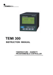
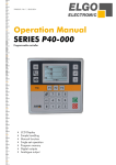
Motion Sensor design structure
The Motion Sensor is constructed utilizing a primary base and a removable cover together with an
infrared lens. Installed inside are a signal receiver, a transceiver with antenna, a battery, a light diode
indicator, an anti-tampering sensor (tamper) and two jumpers for setting modes (see diag.5).
Diag.5 Motion Detector Circuit Board View
Chart 8- Jumper definitions
Jumper position
Closed
“KC”
Open
Closed
“CB”
Open
Selected mode
Send notification “Enclosure opened”
Do not send notification “Enclosure opened”
Reduced sensitivity
Normal sensitivity
Chart 9- Light indicators
Motion sensor state
Normal
Red indicator
Not lit
11
Notification sent
Battery voltage below normal
“Armed” mode entered
Conclusion of the GSM Power Switch “programming”
mode
single or a series of flashes
flashes once every 8 seconds
series of 3 flashes
series of 3 flashes
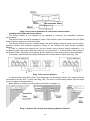
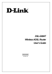
Installation recommendations
The Motion Detector should be installed in a manner that takes into account the likely path of a
violator crossing into and thru the axis of the protected zone. The recommended installation height is
approximately 2 to 2.5m. At an installation height of 2m, the detection range is approximately 10 m, at a
view of 87 degrees (see diag.6). The presence of objects in the protected zone, such as furniture,
screens, plants, etc., might create "blind spots" and possibly interfere with the detection of human
movement.
Diag. 6 Detection zone description
The Motion Detector is not intended to be operated in corrosive and potentially explosive
environments.
The surface on which the Motion Detector is mounted should not be subject to vibration. Do not
install the Motion Detector near strong heat sources (air conditioners, radiators, heaters, etc.) or in any
location subject to strong air currents, sudden air temperature changes or direct sunlight (see diag. 7). It
is possible to reduce Motion Detector sensitivity by placing the “CB” jumper into the closed mode position.
Diag. 7 Examples of improper installation
The Motion Detector should be installed in a spot, at the location, that is not hindered from the
GSM Power Switch by concrete or thick brick walls.
12
The Motion Detector should be installed away from high voltage electrical wiring, electric lamps,
electronic devices and computer equipment. Doing so, will increase radio channel operating distances
and help avoid false alarms.
In order to quickly verify proper radio channel signal operation at the selected installation spot, the
“Enclosure Opened” notification indicator feature can be used. The verification can be done after the
Motion Detector is registered and the “KC” jumper is placed in the closed position. Each flash of the
indicator light diode represents a signal dispatch. If after pressing or releasing the tamper lever, the
light diode indicator flashes 1-2 times, then the communication channel is adequately strong. If there
are 3 flashes or more, then the distance to the GSM Power Switch is too far or the selected installation
spot is inadequate.
Installation and mounting of the Motion Detector at the selected spot should be executed in
accordance with the instructions found in the device’s operating manual.
If necessary, verification of operation and detection zone adjustments can be made by moving thru
and around the area after the GSM Power Switch has been armed.
3.2
Door/ Window Sensor Switch DWS102
The radio channel magnetic Door/ Window Sensor Switch (further referred to as Sensor Switch)
serves to detect the unauthorized opening of doors, windows, hatches, etc. and to transmit an “Alarm”
notification via radio channel to the GSM Power Switch. It contains a built-in magnetic Sensor Switch
and an “Enclosure Opened” sensor (Tamper). Additional passive magnetic switch sensors can be
connected by means of an external wired circuit loop.
Primary technical specifications for the Sensor Switch can be found in chart 10.
Chart 10- Primary technical specifications
Parameter description
Value
Distance (Between sensor & magnet) at which an “Alarm” signal is
generated
12mm & greater
Distance at which “Normal” mode is restored
10mm & less
Maximum length of an external wired loop
10m
Impedance of the external wired loop resistor
7.5 kOhm
Type of power source
CR123A (3V lithium)
Battery operating span, not less than
3 years
Radio signal frequency spectrum
fr 433.05 to 434.79 MHz
Radio signal operating range; “line of sight”*
100m
Maximum transmitter power
5 mW
Interval at which “Heartbeat” control Signal transmits
hourly
Operating temperature range
fr -10 to +50 °C
Dimensions, not exceeding
109×32×27,5 mm
Dimensions of magnet, not exceeding
56,5×18×15,7 mm
Weight of the Sensor Switch / magnet, not exceeding
60 g / 10 g
Service operating life, not less than
10 years
*- Indoor radio signal operating range is affected by construction materials used and the installation
location inside the premises.
Installation recommendations for radio channel devices are shown in Chart 7.
The Sensor Switch transmits the following types of notifications:
“Alarm”- when the magnetic Sensor Switch is triggered;
“Enclosure opened”- when the tamper contacts are opened or closed;
“Heartbeat control”- periodically sent to confirm and verify Sensor Switch operation.
13
When transmitting notifications, a two-way exchange with acknowledgement is utilized.
Transmitted information is encoded, thereby preventing the use of substitute devices and unauthorized
operation of the GSM Power Switch.
Notifications are sequenced in the following order:
After power-up, transmission of all signals by the Sensor are blocked for one (1) minute;
Minimum interval time between the transmission of “Alarm” notifications is one (1) minute;
“Enclosure opened” and “Heartbeat control” are transmitted in both “Armed” and “Disarmed”
modes;
The Sensor Switch receives its power from a single (1) battery. Power up occurs when the tamper
lever is depressed and the protective plastic insert is removed from in between the battery and battery
holder.
Attention! When installing or replacing with a new battery, make sure to keep the tamper lever
depressed.
Sensor Switch Design Structure
The Sensor Switch is constructed utilizing a removable cover, a primary base and circuit board.
The cover snaps into and attaches to the base. Installed on the circuit board are a battery, a magnetic
sensor, a “KC” jumper, a two color LED indicator, an anti-tampering sensor (tamper) and terminal
blocks permitting external connections (see diag.8). A “>” mark can be found on the cover indicating
the location of the magnetic sensor.
Diag.8 Sensor Switch Circuit Board View
Chart 11- “KC” jumper definitions
Jumper position
«КС»
Selected mode
Closed
Send notification “Enclosure opened”
Open
Do not send notification “Enclosure opened”
Chart 12- Light indicators
Sensor Switch state
Normal
Notification sent
Battery voltage below normal
“Armed” mode entered
Conclusion of the GSM Power Switch “programming”
mode
14
Red indicator
Not lit
Single or a series of flashes
Flashes once every 8 seconds
Series of 3 flashes
Series of 3 flashes
Diag. 9 Overview of installation & connection measurements
Installing and Testing the Sensor Switch
The Sensor Switch is not intended to be operated in corrosive and potentially explosive
environments.
The Sensor Switch should be installed in a spot, at the location, that is not hindered from the GSM
Power Switch by concrete or thick brick walls.
The Sensor Switch should be installed away from high voltage electrical wiring, electric lamps,
electronic devices and computer equipment. Doing so, will increase the radio channel operating
distance.
In order to activate the magnet built into the sensor during Sensor Switch registration, it is
necessary to place the magnet that came with the unit, near to the “>” mark located on the housing of
the Sensor Switch. Otherwise, the magnetic Sensor Switch will not process properly during operation.
If necessary, attach additional Sensor Switches to the Sensor Switch inputs (see diag. 10a).
a
b
Diag. 10 Connection diagram
In case the Wire Loop (WL) circuit is not employed, the terminating resistor (Rt) must be directly
connected to the WL and “I” inputs (see diag. 10b). The lack of a terminating resistor (Rt) will cause
the unit to trigger unwanted Alarms.
Basic options for locating Sensors Switch are shown in diagram 11.
Diag. 11 Options for locating and deploying Sensor Switches
15
In order to quickly verify proper radio channel signal operation at the selected installation spot, the
“Enclosure Opened” notification indicator feature can be used. The verification can be done after the
Sensor Switch is registered and the “KC” jumper is placed in the closed position. Each flash of the
indicator light diode represents a signal dispatch. If after pressing or releasing the tamper lever, the
light diode indicator flashes 1-2 times, then the communication channel is adequately strong. If there
are 3 flashes or more, then the distance to the GSM Power Switch is too far or the selected installation
spot is inadequate.
Installation and mounting of the Sensor Switch at the selected spot should be executed in
accordance with the instructions found in the device’s operating manual.
3.3
Alarm Siren SN1-A
The wireless SN1-A siren (further referred to as Siren) is designed to sound an Alarm in operating
with the GSM Power Switch.
In addition to sounding an Alarm, the Siren functions as a sound and light annunciator in order to
acknowledge system arming and disarming.
Basic technical specifications for the Siren are shown in chart 13.
Chart 13- Basic technical specifications
Parameter description
Loudness sound level at a distance of 1m
Maximum radio channel signal range with the GSM Power Switch
Battery type
Battery operating life
Temperature operating range
Value
85-95 dB
100 m
Lithium battery CR123A 3V
12 months
Fr -10 to +50 °C
Wireless Siren design structure
The Siren consists of a base, a cover, a circuit board and a sound annunciator. The Siren circuit
board contains a jumper (J2) that serves to turn on or off the audio sound confirmation feature during
Arming and Disarming. When the jumper is in the closed position, the audio sound confirmation
feature is not available. The base and cover attach to each other using a single screw that can be
found at the lower part of the unit.
The Siren mounts in any convenient manner on a hard surface using two screws.
Power is provided by a CR123A 3V Lithium battery. The battery should be installed using proper
polarity as indicated on the circuit board.
Diag.12 Siren plate
16
The Siren provides light and sound alerting. A description of notification alerts can be found in
chart 14.
Chart 14- Siren Notifications
Notification
Power-up
Registration confirmation
Alarm device Armed
Acknowledgement
Alarm device Disarmed
Acknowledgement “ALARM”
Sound alert
1 Sound chirp
1 Sound chirp
1 Flash
3 Flashes
1 Sound chirp
1 Flash
2 Sound chirps
2 Flashes
Flashes periodically During 1
minute
Sounds periodically during 1 minute
Light alert
Chart 15- Audio sound Armed/ disarmed confirmations
Jumper position J2
Audio sound confirmations for Armed/ Disarmed modes
Closed
No
Opened
Yes
4
SET-UP PROCEDURE
4.1
Preparing the Device for Operation
Purchase a new SIM card (preferably M2M; machine to machine). Prior to set-up, de-activate the
PIN code request feature on the GSM Power Switch SIM card by using a GSM type telephone (refer to
the instructions found in the telephone Operating Manual) and turn-off any additional extra services
found on the SIM card. Confirm that the SIM card memory is cleared and that an adequate balance is
available.
If the SIM card was previously used, execute erasure of the phonebook (4.4).
After opening the package, visually inspect the GSM Power Switch to make sure there is no
physical damage and that all the parts are present.
4.2
Setting Up the GSM Power Switch
All GSM Power Switch settings are saved to and kept in the SIM card memory. When powered up for
the first time with a new SIM card, the GSM Power Switch creates a values template in accordance with
chart 16.
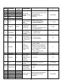
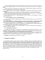
Chart 16- Setting up the GSM Power Switch Parameter Values
Default
Cell# Cell label
Description
Value
1st notification Enter number in the following
1
1sms
000
tel. number
format
(primary)
+1**********
2
2sms
000
3
3sms
000
Enter number in the following
Notification tel.
4
4sms
000
format
numbers
+1**********
5
5sms
000
6
6sms
000
Remaining
balance Inquiry
US. Auto
Manual entry of remaining
detection of
7
BALANCE
0
balance command for
remaining
specific provider
balance
command for
major providers
17
Possible Values
or
+17180000000
+171800 00000
*100#
Cell#
8
9
10
11
12
13
14
15
16
17
18
19
20
22
25
26
27
28
29
30
31
Default
Description
Value
RC#1
000000000
RC#2
000000000
Entered automatically during
RC#3
000000000 Factory set
RC registration.
RC#4
000000000 Remote Control 000000000 - RC not
number
registered
RC#5
000000000
RC#6
000000000
Frequency for
Interval sets in Days.
Test/ heartbeat
TEST
7
0- Test/ heartbeat SMS
SMS
notification disabled
notification
00000 - Password disabled
Password to
by default.
Password
00000
control from
Commands blocked from all
non-registered tel.’s
Send SMS
when armed/
0 - Disable Send
ArmDisarm
1
disarmed mode 1 - Enable Send
activated
Reset time to
re-Arm after a
0 - 250 seconds
AvtoArm
60
triggered Alarm;
0 - Reset disabled
no notification
Sent
0 - SMS sent to1sms...6sms
1 - Call + SMS;
Alarm
SMS sent to 1sms, then calls
notification
placed to all tel. numbers,
AlarmNot
1
Option/Type
followed by SMS transmittal
during Alarm
to all remaining tel. numbers
mode
“2sms... 6sms”;
3 - Only calls placed to
“1sms...6sms”
ArmDelay
40
Arming delay
0 - 250 sec.
Notification
delay, after
NotDelay
20
triggered alarm 0 - 250 sec.
to permit
disarming
Auto Recorded registration;
Unique Siren ID
Siren
000000000
000000000- device not
Number
registered
Turns Alarm
Sensor sound
0 – On
TriggerAlarm 0
off/on during
1- Off
triggered alarm
SIGNAL1
000000000
SIGNAL2
000000000
Auto Recorded registration;
SIGNAL3
000000000 Unique Sensor
000000000-device not
SIGNAL4
000000000 ID Number
registered
SIGNAL5
000000000
SIGNAL6
000000000
Cell label
18
Possible Values
or
123456789
7 – 7 days
12345
0
120
0
125
100
123456789
0
123456789
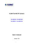
Cell#
Cell label
32
RelayAlarm
33
BlockRelay
Mode
Default
Value
0
000000
Possible Values
or
Description
Using Relay
Output During
Alarm
Button A&B
mode type
0- Do not use
1- Close Relay
2- Open Relay
1- “A” Panic “B” Arm/Disarm
0 -“A” Arm
“B” Disarm
2
010011
RC 1,3&4
Button “A”- Arm,
Button “B”- Disarm
RC 2,5&6
Button “A”- Panic,
Button “B”Arm/Disarm
Service parameters, created
Template name
in Socket template during
w/settings
set-up
35 AlarmNmb
000
Service Cell
Alarm Device Tel.#
+17180000000
SMS
0-Ru
36 LANG
0
Notification
1
1-En
Language
For example, if cell “Auto Arm” (see chart 6, cell 17) contains “90”, then after a triggered Alarm, the
GSM Power Switch will pause for 90 seconds, after which, it will re-enter “Armed” mode.
34
SOCKET
0
For example, if cell “Not Delay” (see chart 6, cell 20) contains “40”, after a triggered alarm, the
“Alarm” notification transmission will be delayed 40 seconds in order to facilitate Disarming.
4.3
Accessing Programming Mode
The GSM Power Switch can access programming mode via 2 methods.
Method 1
In order to access GSM Power Switch programming mode, execute the following steps
consecutively.
1. Lift-off the battery compartment cover.
2. Remove the battery and insert a SIM card into the slot.
3. Replace the battery using proper polarity.
4. Wait for a single audible beep. Light diodes “ZONE”, “LINK” & “POWER” will glow a steady
orange indicating power-up.
5. Wait for the SIM card to log on to the network. Upon completion of log on, 3 audible beeps are
heard. The “ZONE” light diode will glow orange, while “LINK” indicates GSM signal strength (greengood or red- poor) and “POWER” is not lit-up. This indicates that the GSM Power Switch has
accessed programming mode.
Method 2
In order to access the GSM Power Switch programming mode from “Standby” mode, press down
button “R” until the “ZONE” indicator lights up (glows steady orange and “LINK” indicates GSM signal
strength).
Caution! While accessing programming mode, do not press button “R” in excess of hearing 4
audible beeps. Otherwise, all previous settings will be cleared from the SIM card.
For a span of 60 seconds the GSM Power Switch waits for incoming calls and for connection
inquiries from Remote Controls, Sirens and SMS’s containing changes in settings (each one of these
actions will extend the GSM Power Switch wait period for an additional 60 seconds). After the wait
19
period expires, the GSM Power Switch will enter "Disarmed” mode and transmit an SMS notification
indicating all added devices to the primary telephone number.
4.4
Erasing the Telephone Book (Creating the Default Template)
If the SIM card was previously used in a GSM Power Switch, it will be necessary to create a
default template. Execute the following steps consecutively.
1. Install a SIM card.
2. Press and hold down the "R" button for a duration of 5 beeps. When the beeps cease, all the
indicators will glow orange.
3. Release the button. An audible beep will confirm erasure.
4. The Indicator will show that the GSM Power Switch is in the programming mode ("Zone" light
diode glows a steady orange, "Link" shows GSM signal strength (green- strong or red- weak) and
"Power" is not lit-up).
After the template is created, the SIM card is now ready for further set-up.
4.5
Initial Programming (Set-Up)
When the GSM Power Switch powers up for the first time, cells will be created in the SIM card
telephone book containing default parameter values. In the future, these values can be edited.
Execute the following steps consecutively.
1. Access programming mode in the device (see 4.3).
2. Add telephone numbers for notifications (see 4.7).
3. Add the Siren (see 4.9).
4. Add Keychain Remote Controls (4.11).
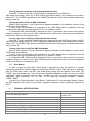
5. Add Alarm Sensors & Motion Detectors (see 4.13).
6. The primary telephone number will receive an SMS notification indicating all added devices; an
SMS showing settings (see diag.13) and an SMS showing all registered Keychain Remote Controls,
the Siren and detector sensors (see diag.14).
Diag. 13- SMS w/ Settings Description
Diag. 14- SMS w/ Registered Devices
20
4.6
Changing the Value Parameters
The value parameter settings that were created at first power-up can be changed. The parameter
values can be changed using a few methods.
Method 1
The GSM Power Switch settings can be changed with the aid of an online service (service.alphasafe.ru), an OS Android App from google.play.com or an iOS App from I tunes (search “GSM Power
Switch”).
Method 2
1. Create an SMS message using values in accordance with Chart 16. For example, in order to
change the type of notification, an SMS message must be sent from a registered telephone to the
GSM Power Switch SIM card telephone number containing this text (text is entered w/o angle
brackets): <<18)0>>, where: 18) is the cell number; and 0 is the parameter value. In order to change a
number of parameter values, the listed parameter values must be separated by a comma; for
example: <<16),18)0>>
2. Send the created SMS message to the GSM Power Switch SIM card telephone number.
Method 3
It is also possible to change the parameter values directly via a GSM telephone. In order to
accomplish this, install the SIM card into a GSM telephone, access the required cell # via the phone
book (in accordance with Chart 16) and then edit the parameter value accordingly.
Attention! This method cannot be used to register Keychain Remote Controls, Detectors/ Sensors
and Sirens.
4.7
Adding Notification Telephone Numbers
Notification telephone numbers can be added in the following manner:
1. Access programming mode in the GSM Power Switch (see 4.3). For a span of 60 seconds, the
GSM Power Switch will wait to receive incoming calls.
2. Place a call from the telephone number to be added to telephone number of the GSM Power
Switch SIM card.
3. Wait for the GSM Power Switch to pick-up, then drop the incoming call and then confirm
registration with a single audio beep. The telephone number will be recorded at an available cell
position@ <<2sms>>…<<6sms>>.
4. The telephone number from which the call was made will receive an SMS response showing the
added telephone number. For the next 60 seconds, the GSM Power Switch will wait for additional
incoming registration calls (up to 6 telephone numbers can be added).
Notification telephone numbers can be added using any of the methods described in 4.6.
4.8
Deleting Notification Telephone Numbers
In order to delete a telephone number from the notification list, execute the following steps.
1. Send an SMS from a registered telephone to the SIM card telephone number of the GSM
Power Switch containing the following text (text is entered w/o angle brackets): <<2)000>>- in order to
delete the second notification telephone number, <<3)000>>- in order to delete the third notification
telephone number, etc.. In order to delete multiple notification telephone numbers, separate the listed
parameter values with a comma. For example; <<2)000,3)000,4)000,5)000,6)000>>- This deletes all
the listed additional notification telephone numbers.
In case the telephone number from which deleting is not registered with the GSM Power Switch,
then the SMS needs to be composed with a password (see 4.15).
2. The GSM Power Switch will emit 1 audible beep or a number of audible beeps, depending on
the length of the SMS message.
21
4.9
Adding the Wireless Siren
1. While the GSM Power Switch is in programming mode, power-up the Siren by removing the
protective plastic insert from in between the battery and the battery holder. This Siren will be
registered in cell 22 <<Siren>>. Upon power-up, the Siren’s light diode’s will flash once and a short
beep is heard. When registration is completed, the Sirens light diodes will flash three times and a short
beep is heard.
2. Wait for the GSM Power Switch to beep once.
3. An SMS will arrive on the telephone indicating the added Siren.
Attention! The GSM Power Switch memory permits the registration of only one Siren. In the event
that a second Siren is registered, the GSM Power Switch will automatically delete the previously
registered Siren.
4.10 Deleting the Wireless Siren
In order to delete a previously registered Siren from the GSM Power Switch memory, execute the
following steps.
1. Send an SMS from a registered telephone to the SIM card telephone number of the GSM
Power Switch containing the following text (text is entered w/o angle brackets):<<22)000000000>>.
In case the telephone number from which deleting is not registered with the GSM Power Switch,
then the SMS needs to be composed with a password (see 4.15).
2. The GSM Power Switch will emit 1 audible beep.
Attention! Delete a registered Siren from the GSM Power Switch memory in the event its power is
turned off or if it is located outside its operating range.
4.11 Adding a Keychain Remote Control
1. While in programming mode, press any button on the Keychain Remote Control in order to
register it in the SIM card memory. This Keychain Remote Control will be registered in cell 8 as
<<RC1>> (see chart 16).
2. The Keychain Remote Control light diode will glow orange, then during the registration process
the light diode will alternately flash red and green. Upon completion of registration, 1 audible beep will
be heard and the light diode indicator will turn off.
3. An SMS will arrive on the telephone indicating the added Keychain Remote Control.
Repeat these steps in order to register additional Keychain Remote Controls (up to 6 Keychain
Remote Controls may be registered).
4.12 Deleting a Keychain Remote Control
In order to delete previously registered Keychain Remote Controls, execute the following steps
consecutively:
1. Send an SMS from a registered telephone to the SIM card telephone number of the GSM
Power Switch containing the following text (text is entered w/o angle brackets): <<8)000>>- in order to
delete RC1, <<9)000>>- in order to delete RC2, etc.. In order to delete multiple Keychain Remote
Controls, separate the listed parameter values with a comma. For example;
<<8)000000000,9)000000000,10)000000000,11)000000000,12)000000000>>- This deletes all the
listed additional Keychain Remote Controls.
In case the telephone number from which deleting is not registered with the GSM Power Switch,
then the SMS needs to be composed with a password (see 4.15).
2. The GSM Power Switch will emit 1 audible beep or a number of audible beeps, depending on
the length of the SMS message.
4.13 Adding Alarm Sensors & Motion Detectors
1. Access programming mode in the GSM Power Switch.
2. Open the Alarm Sensor or Motion Detector enclosure.
22
3. While keeping the tamper lever depressed, power-up the Alarm Sensor or Motion Detector by
removing the protective plastic insert from in between the battery and the contacts or by installing a
battery.
4. At the conclusion of registration, the Alarm Sensor or Motion Detector indicator will blink red 3
times and the GSM Power Switch will emit 1 audible beep.
5. An SMS will arrive on the telephone indicating the added Alarm Sensor(s) and/ or Motion
Detector(s).
Repeat these steps in order to register any additional Alarm Sensors and/ or Motion Detectors.
Attention! Whenever an Alarm Sensor and/ or a Motion Detector is powered-up, it is necessary to
keep the tamper lever depressed until the light diode indicator lights up.
Up to 6 Alarm Sensors and / or Motion detectors of these 2 types can be registered in the GSM
Power Switch memory.
4.14 Deleting Alarm Sensors & Motion Detectors
In order to delete previously registered Alarm Sensors & Motion Detectors, execute the following
steps consecutively:
1. Send an SMS from a registered telephone to the SIM card telephone number of the GSM
Power Switch containing the following text (text is entered w/o angle brackets): <<26)000000000>>- in
order to delete Sensor/Detector1, <<26)000000000>>- in order to delete Sensor/Detector 2, etc..
In case the telephone number from which deleting is not registered with the GSM Power Switch,
then the SMS needs to be composed with a password (see 4.15).
2. The GSM Power Switch will emit 1 audible beep or a number of audible beeps, depending on
the length of the SMS message.
4.15 Changing the Password
By default, the password for controlling and managing the GSM Power Socket via a nonregistered telephone is- “00000” (see chart 16, cell 15). This means that the password feature is deactivated, i.e. all commands from non-registered telephones are not allowed.
In order to change the password, it is necessary to send an SMS containing a new password from
a registered telephone. For example (text is entered without the angle brackets): <<15)12345>>; now
the device can be controlled and managed from a non-registered telephone.
Attention! The password must consist of 5 numerals.
5
WARRANTY COVERAGE
The warranty period is one year from date of purchase. During the warranty period, the
manufacturer will repair, exchange, adjust, or replace at its discretion, any defective product. This
warranty does not cover damage resulting from any unauthorized attempts to repair or from any use
not in accordance with the instruction manual. The warranty does not cover physical damage of any
kind whatsoever nor does it cover damage caused by any attempt to tamper with or disassemble the
product. The warranty coverage does not extend to the batteries. The warranty period commences on
the day first purchased from the manufacturer or an authorized reseller as evidenced by a purchase
receipt. Without a valid purchase receipt, the manufacturer is relieved of its obligation to provide
warranty service.
23