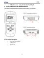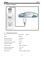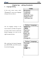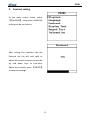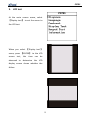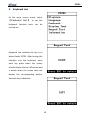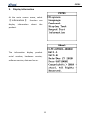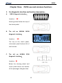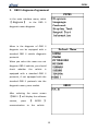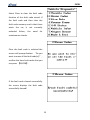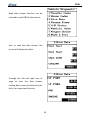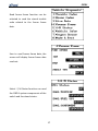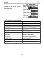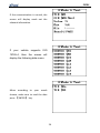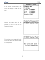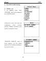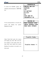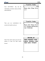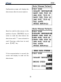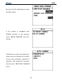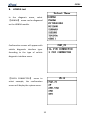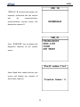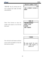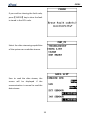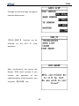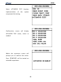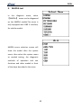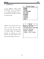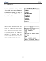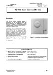
1
 PS701 STATEMENT (1) This manual is designed for the PS701 product, any company or individual are not permit to replicate and backup it in any form if they don't have the authority license from XTOOLTECH CO., LTD (include electronic, mechanical, photocopying, recording or others). (2) PS701 is just offered for the professional and technical personnel of vehicle maintenance (3) This manual only provides methods of operating PS701 products, our company does not undertake any responsibility if it result in any consequences by operating other equipments. (4) XTOOLTECH does not undertake any responsibility if the equipment is damaged or let users cost or loss any expenditure because of the user's personal or third‐party’s accident; or abuse or misuse of the equipment; or unauthorized alteration and repair; or wrong operating not guide by manual, etc. (5) The manual is based on the existing configuration and functions, and it will also be subject to change if the tool is added new configuration and new features, but please pay attention that we wont notice it specially. (6) XTOOLTECH Company has conducted a registration of trademarks, the logo is (7) XTOOLTECH Company claim that it still owns the ownership of 0 PS701 trademarks, service marks, domain names, logos and company names among the nationals where those have not yet be registered . The other products and other company names mentioned by the manual still belong to the original registered companies. nobody can use the name of XTOOLTECH or the trademarks, service marks, domain names, logos and company names if without the formal agreement written by the consent of the XTOOLTECH owner, (8) You can access the web site: http://www.xtooltech.net to learn more about the related information of PS701 equipment. (9) XTOOLTECH company owns the final interpretation of the manual contents. 1 PS701 Notes (1) vehicle power supply must meet the normal operating voltage, such as the 10V‐12V. (2) test harness plug wiring harness should be front and hold hands bulk of the plug, not pulling the middle section of wiring harness, wiring harness plug the interface when the first check the corresponding plug, plug is not placed at an angle to avoid Damage to the pins. (3) PS701 test menu test vehicle was not found or the system may not be a software upgrade or to the company's technology service department. (4) prohibit the use of non XTOOL harness technology company supporting the connection test, so as to avoid unnecessary damage. (5)
rohibits the testing process on the vehicle disconnect the TF card to avoid data loss. (6)
ommunication with the vehicle in PS701, the ban on direct shutdown. Canceled after the first task should be to return to the main interface to shut down. (7)
hen using the PS701 gently to avoid vibration or shock. (8) PS701 diagnostic equipment when not in a long time, disconnect the power supply and then turned off. 2 PS701 Directory lists Chapter one acquaintance of product............................................................ 5 1、PS701 Appearance and interface diagram.................................................. 5 2、Diagnostic diagram ..................................................................................... 6 3、Technical parameters ................................................................................. 6 Chapter two setting of products .................................................................... 7 1、Language Setting......................................................................................... 7 2、Contrast setting .......................................................................................... 8 3、LCD test....................................................................................................... 9 4、Keyboard test............................................................................................ 10 5、Display information .................................................................................. 11 Chapter three PS701 use and common functions......................................... 12 1、Car diagnostic interface and location description .................................... 12 A. OBD II diagnostic interface ............................................................ 12 B. The old car NISSAN 14PIN.............................................................. 12 C. The old car HONDA 3PIN................................................................ 12 2、OBD II diagnose of agreement .................................................................. 13 3、By vehicle model testing ........................................................................... 26 A. TOYOTA test................................................................................ 26 B. HONDA test.................................................................................... 32 3 PS701 C. NISSAN test ...................................................................................... 37 D. MITSUBISHI test............................................................................... 43 E. MAZDA test .................................................................................... 49 F. SUBARU test..................................................................................... 50 G. SUZUKI test...................................................................................... 51 4 PS701 Chapter one acquaintance of product 1. PS701 Appearance and interface diagram
The product outward appearance take the material object as a standard. PS701 The interface at the top: PS701 The interface below: PS701 Interface Description: ①
:Main test line interface ②
:USB interface ③
:TF card slot 5 PS701 2. Diagnostic diagram 3. Technical parameters CPU: ARM 32 CPU 72MHz RAM: 64K Ram Program Memory: 512K Flash External memory: TF card Mainframe power supply: DC12V Mainframe power: 8W Display Screen: 160mm×160 mm Ambient temperature: ‐20—50℃ Relative Humidity: <90% Dimensions: 225mm * 98mm *36mm 6 PS701 Chapter two setting of products 1. Language Setting At the main screen menu, select 【Language】 setup menu language setting can be carried out. Into the language settings in the menu interface, available through the up arrow, down arrow to select the desired language, can also be left, right for page selection. After selecting the desired language press 【ENTER】 to the PS701 is set to the selected language. 7 PS701 2. Contrast setting At the main screen menu, select 【Contrast】 setup menu contrast setting can be carried out. After setting the interface into the Contrast via the left and right to adjust the screen contrast can also be up and down keys to fine‐tune. Adjust the contrast, press 【ENTER】 to save the settings. 8 PS701 3. LCD test At the main screen menu, select 【Display test】 to set the menu to the LCD test. When you select 【Display test】 menu, press 【ENTER】 to the LCD screen test, this time can be observed to determine the LCD display screen shows whether the failure. 9 PS701 4. Keyboard test At the main screen menu, select 【 Keyboard test 】 to set the keyboard function tests can be carried out. Keyboard test whether the key is to detect faults PS701. After testing the interface into the keyboard, press each key press when the screen should display the key. When pressed a button when the screen does not display the corresponding button, then the key is defective. 10 PS701 5. Display information At the main screen menu, select 【 information 】 function can display information about the product. The information display product serial number, hardware version, software version, date and so on. 11 PS701 Chapter three PS701 use and common functions 1. Car diagnostic interface and location description:
A.
OBD II diagnostic interface: Location:(●) Steering wheel below the top of the clutch pedal. B.
The old car NISSAN 14PIN diagnostic interface: Location:(●) The top of the clutch pedal, instrument panel bottom left of the fuse box. C.
The old car HONDA 3PIN diagnostic interface: Location:● Below the steering wheel and clutch pedal above the bottom of the passenger side glove box. 12 PS701 2. OBD II diagnose of agreement In the main interface menu, select 【 diagnose 】 to the OBD II diagnostic menu diagnosis. Menu in the diagnosis of OBD II diagnosis can be equipped with a standard OBD II vehicle diagnostic protocols. When you select the menu can not diagnose OBD II vehicles, you should check whether the vehicle is equipped with a standard OBD II protocols, if not equipped with the standard OBD II protocols into the diagnostic menu, press models. After selecting the menu screen 【OBD II 】will display the software version, press 【
ENTER
】 communication to the vehicle. 13 PS701 At this point the vehicle OBD II diagnostic protocol will be scanned. If the communication is normal diagnostics menu screen will appear, according to the functional needs of your menu. After reading the fault code menu selection screen will display to read out the fault code and definitions. If you read a number of fault code, press 【ENTER】 key to scroll down view. 14 PS701 Select Clear to clear the fault code function of the fault code stored. If the fault code and then clear the fault code memory read is that there exists the car is not currently excluded failure, the need for maintenance checks. Clear the fault code is selected the screen will prompt feature ‘Do you want to erase all the fault code(s)?’, confirm the clear fault codes that you can press 【ENTER】. If the fault code cleared successfully, the screen displays the fault code successfully cleared! 15 PS701 Read data stream function can be selected to read OBD II data stream. Sure to read the data stream, the screen will display the data. Through the left and right keys to page to view the data stream, reading data stream to determine the fault is an important function. 16 PS701 Read freeze frame function can be selected to read the stored trouble code related to the freeze frame data. Sure to read freeze frame data, the screen will display freeze frame data read out. Select I / M Status function can read the OBD II system components of the switch and functional status. 17 PS701 Through the left key and right key page can be read. I/M Status data item comparative table Abbreviated Name Expanded Name Misfire Monitor Misfire monitor FUEL System Mon Fuel System Monitor Com Component Comprehensive Components Monitor Catalyst Mon Catalyst Monitor Htd Catalyst Heated Catalyst Monitor Evap System Mon Evaporative System Monitor Sec Air System Secondary Air System Monitor A/C Refrig Mon Air Conditioning Refrigerant Monitor OXYGEN Sens Mon Oxygen Sensor Monitor Oxygen Sens HTR Oxygen Heater Sensor Monitor EGR System Mon Exhaust Gas Recirculation System Monitor 18 PS701 Vehicle Information menu options relevant information can be read. Select Vehicle Infor will be displayed after the vehicle information. If the vehicle does not support this feature screen will display 'Not Support! '. 19 PS701 Select Oxygen Sensor menu to read the Oxygen Sensor relevant data values. After reading the Oxygen Sensor confirmation screen will show each group the sensor menu, choose required to read. If the vehicle does not support this mode, the screen will show 'The selected mode is not supported'. 20 PS701 Oxygen sensor test is not supported for CAN,please select service $06. If the communication is normal, the screen will display select screen, according to the maximum and minimum need to select the read. 21 PS701 Disp test result. Oxygen sensor data item comparative table Abbreviated Name Expanded Name RichToLeSeThV(Con) Rich to lean sensor threshold voltage (constant) LeanToRiSeThV(Con) Lean to rich sensor threshold voltage (constant) LowSeVFoSwTiCA(Con) Low sensor voltage for switch time calculation (constant) HighSeVoFoSwTiCa(Con) High sensor voltage for switch time calculation (constant) RichToLeSwTi(Cal) Rich to lean sensor switch time (calculated) LeanToRiSeSwTi(Cal) Lean to rich sensor switch time (calculated) MinSeVoForTeCy(Cal) Minimum sensor voltage for test cycle (calculated) MaxSeVoForTeCy(Cal) Maximum sensor voltage for test cycle (calculated) TimeBeSeTr(Cal) Time between sensor transitions (calculated) Sensor period(Cal) Sensor period (calculated) 22 PS701 Select 'Mode 6 Test' menu to test a vehicle's catalytic converter conversion results, the diagnosis of secondary air system, evaporation control test results. As a result of different definitions of car manufacturers on the TID, you must know the manufacturers of the TID values corresponding to the data to determine the definition. According to their need for menu selections, such as the confirmation test press 【ENTER】 key. 23 PS701 If the communication is normal, the screen will display reads out the relevant information. If
your
vehicle
supports
ISO
15765-4, then the screen will
display the following data menu. Menu according to your needs choose, make sure to read the data press 【ENTER】 key. 24 PS701 If the normal communication, the screen will display to read out the data. Chooses the EVAP menu to be possible to carry on the test to Evaporative System. If the vehicle is not supported by the screen will show 'The selected mode is not supported'. 25 PS701 3. By vehicle model testing A.
TOYOTA test In the diagnosis menu, select 【TOYOTA】 menu can be diagnosed on the TOYOTA models. Confirmation screen will show the configuration menu selection interface CANBUS, according to the vehicle's configuration menu. 【 WITHOUT CANBUS 】 menu to select example, into the display system will be classified according to the need for choice. 26 PS701 To select the ENGINE system, for example, select and press 【ENTER】 key. If the communication is normal, the screen will display the system diagnostics menu. Select Read fault code, the screen will display the fault code read out the number, if the system does not have fault code stored, the screen displays the system to normal or no fault code. 27 PS701 Press 【 ENTER 】 key can be individually read fault codes and fault code definition. Then you can troubleshoot the content of trouble code out. Select Clear fault codes menu for the system to clear the fault codes stored. 28 PS701 Clear the fault code feature selection screen will display to confirm the clear trouble code, clear fault code if the confirmation, press ENTER】 key. Press 【 ENTER 】 , the screen will display fault code cleared successfully. Then if we read the trouble code also shows a fault code stored there is currently no solution is the fault, the need for vehicle maintenance. Select Read data stream real‐time data can be read, the function is to determine the fault for further important function. 29 PS701 Confirmation screen will display the data stream after the menu options. Need to read the data stream in the position of press 【ENTER】 key to select to read the data before the data items with "*" were selected to read. Choosing a data item to read, press 【ESC】 key. If the communication is normal, the screen will display to read out the data stream. 30 PS701 By press the left, right page can view the data stream. If the vehicle is equipped with CANBUS protocol, in the previous menu 【WITH CANBUS】 menu for testing. Confirmation screen will display the system menu, according to the needs of your menu selection, methods of operation and diagnostic functions with the same 【WITHOUT CANBUS】 menu. 31 PS701 B. HONDA test In the diagnosis menu, select 【HONDA】 menu can be diagnosed on the HONDA models. Confirmation screen will appear with vehicle diagnostic interface type. According to the type of vehicle diagnostic interface menu. 【 16PIN CONNECTOR 】 menu to select example, the confirmation screen will display the system menu. 32 PS701 【PGM‐FI 】 to select the system, for example, confirmed that the vehicle will be communication, communication normal screen will display the system ID. Press 【ENTER】 key to display the diagnostic features of the system menu. Select Read fault codes function, the screen will display the number of fault codes read out. 33 PS701 【ENTER】 key by pressing one by one to display fault codes and fault code definition. Select Clear function to clear the trouble code stored in the ECU the fault code. Clear the fault code feature selection screen will be prompted to clear the fault code to confirm 34 PS701 If you confirm clearing the fault code, press 【ENTER】 key to clear the fault is stored in the ECU code. Select the data streaming capabilities of the system can read data stream. Sure to read the data stream, the screen will be displayed if the communication is normal to read the data stream. 35 PS701 Through the left and right to page to view the data stream. 【 ECM RESET 】 function can be selected on the ECU to reset operation. After confirmation, the screen will display "ECM reset" prompt. If you confirm the operation of the implementation of this function, you can press 【ENTER】 key. 36 PS701 C. NISSAN test In the diagnosis menu, select 【NISSAN】 menu can be diagnosed on the NISSAN models. Enter the menu will display in the AUTO and MANUAL two diagnostic methods. 【AUTO】 menu to select example, the recognition system will scan the vehicle. 37 PS701 Take a little while during the system scan time, please be patient. When the scan results to select the desired systems are tested to ENGINE system for example, can be confirmed by testing the system. Select WORK SUPPORT feature the system can ENGING special functions. 38 PS701 Choose WORK SUPPORT, the screen will display the function of these tips. Select function to read fault codes stored in the system can read the fault code. If the communication is normal, the screen will display the fault code read out the number. 39 PS701 Press 【ENTER】 key to display the code and fault code fault code definition. Select Clear to clear the fault codes stored in the ECU function in a fault code. Confirmation screen will display fault code removal tips. 40 PS701 Press 【ENTER】 to clear the fault code. Read data stream function can be selected to read the system data flow. Confirmation screen will display the data stream classification. 41 PS701 Select the appropriate screen will be displayed after the group read out the data stream. Through the left and right page to read the data stream. Select ACTIVE TEST function on the implementation of the system components for testing. 42 PS701 D. MITSUBISHI test In the diagnosis menu, select 【 MITSUBISHI 】 menu can be diagnosed on the MITSUBISHI models. Confirmation screen will display CANBUS equipped with select menu, according to the vehicle equipped with the menu selection. 【 WITHOUT CANBUS 】 menu for example, after the display area into the menu, select the menu according to region. 43 PS701 After the menu selection area the system will display the menu screen, select the System menu as needed. MPI menu to select example, if the communication is normal, the screen will display the system diagnostics. Select ECU ID function can read the system's ECU ID. 44 PS701 Select Read trouble code function that can read fault codes stored in the system. If the communication is normal, the screen will display fault code number. Press 【ENTER】 key to display fault codes and read out the fault code definition. Select Clear function to clear the fault codes stored in the system fault codes. 45 PS701 Clear the confirmation screen will display fault code tips. Press 【 ENTER 】 key, the screen displays the fault code has been cleared. Select Read to read the data stream data flow of the system. 46 PS701 The system's data stream can read for free choice, in front of each data item you can press 【ENTER】 select or cancel the reading of the data stream, the data item before the show "*" is that the data is selected. After selecting the items you need to read the data, press 【ENTER】 to display the data stream. Through the left and right page can view the data stream. 47 PS701 Select ACTUATOR TEST function implementation of the system components for testing. Confirmation screen will display ACTUATOR TEST menu, select as needed. Before the operation screen will prompt you to confirm the action. Press 【ENTER】 will be tested on selected components. 48 PS701 E. MAZDA test
In the diagnosis menu, select 【MAZDA】 menu can be diagnosed on the MAZDA models.The menu is only equipped with OBD II interface, for vehicle models. MAZDA menu selection screen will show the model after the system menu, then select the system menu as needed testing, the diagnostic methods of operation and test functions and other models in front of the steps described in the same. 49 PS701 F. SUBARU test In the diagnosis menu, select 【SUBARU】 menu can be diagnosed on the SUBARU models.The menu is only equipped with OBD II interface, for vehicle models. SUBARU menu selection screen will show the model after the system menu, then select the system menu as needed testing, the diagnostic methods of operation and test functions and other models in front of the steps described in the same. 50 PS701 G. SUZUKI test In the diagnosis menu, select 【SUZUKI】 menu can be diagnosed on the SUZUKI models.The menu is only equipped with OBD II interface, for vehicle models. SUZUKI menu selection screen will show the model after the system menu, then select the system menu as needed testing, the diagnostic methods of operation and test functions and other models in front of the steps described in the same. 51