1
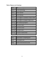
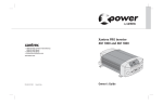
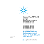
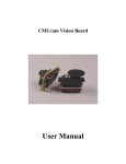
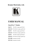
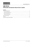
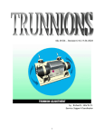
Index Index 1 Synopsis 2 Background – What is a robot? 3 Summary of system operation 4 Specification 5 Circuit descriptions Photologic optosensor module Optosensor indicator module 6,7,8 9 Motor driver control module 10 Variable reference voltage source 11 5V regulated voltage source 12 Microcontroller 13 Microcontroller program code 14 Construction 15 Design history summary 16 Design history Background 17 Detailed design history 18,19,20,21,22 Discussion of project 23 Conclusion 24 Resources and bibliography 25 Table of figures and drawings 26 Appendices 27 -1- Synopsis The purpose of this project was to design, prototype and build, a fully autonomous robot, capable of following a pre-designated path, marked on a surface using insulation tape. The robot was to be designed and built to my own specifications. A full record of the developmental work was to be kept and provided as evidence of the development of the project. The primary objective of this project was to build a line following robot; this objective has been achieved and in doing so has provided me with new skills learnt through the development of the project, and several valuable learning experiences. -2- Background What is a robot? A robot may be defined as: • Robot, any automatically operated machine that replaces human effort, though it may not resemble human beings in appearance or perform functions in a humanlike manner.1 • Robot, computer-controlled machine that is programmed to move, manipulate objects, and accomplish work while interacting with its environment.2 • Robot, any machine which performs physical tasks automatically, which would otherwise have been undertaken by a human operative. Robots are usually remotely controlled by a computer, but some robots have built in computers giving them local intelligence.3 The term robot is derived from the Czech word robota meaning "forced labour." The modern use of the term comes from the play R.U.R, written in 1920 by the Czech author Karel Capek, in which society has become dependent on mechanical workers called robots, that are capable of doing any kind of mental or physical work. There are many types of robots, but the word is most closely associated with a machine that is of humanoid appearance, like Honda’s Asimo robot, show below. Figure 1 - Honda’s Asimo Robot The building of such a machine costs millions of dollars, several years of developmental work and the resources of hundreds of people. 1 2 3 Britannica online (www.brittanica.com) Encarta online (www.encarta.com) rd Newnes Dictionary of Electronics, 3 Edition, 1997 -3- Summary of system operation The project objective was to design and build an autonomous, line following robot capable of following a track marked by a black line (insulation tape) on a white surface. The robot is based around the Basic Stamp 1 microcontroller manufactured by Parallax industries. The microcontroller receives inputs from a pair of infrared sensors (H23LOI – manufactured by Vishay) and from these inputs determines if the robot should continue forward or the direction that the robot should turn. Forward motion is provided by a pair of motor/gearbox driving the rear wheels, these are driven from a pair of motor driver IC’s (BA6286 – manufactured by Rohm), which are controlled from the microcontroller. In order for the robot to turn, one wheel is stopped while the opposite wheel continues to turn. The robot will continue moving forward until neither sensor can see the black line, at that time the robot will turn in the direction of the last sensor seen until one of the sensors can again see the line. Sensor Output 1=Line seen 0=Line not seen Turn in direction of last sensor seen now 1 1 1 1 0 1 0 1 0 1 0 1 0 0 0 1 0 1 0 1 1 1 1 0 1 0 0 0 1 0 1 0 1 1 Truth table I/P 0 0 1 0 0 1 1 1 Next Action Turn Forward Forward Forward Turn! Turn in direction of last sensor seen now Turn! Etc... Etc... Figure 2 - Control methodology -4- Specification Length (max) 290 mm Width (max) 145 mm Height (max) 152 mm Weight (including battery) 1.885 Kg Turning radius (min) 240 mm Power Source 12V 2.3Ah Sealed lead acid battery Electronics Photologic infrared sensors feeding programmable microcontroller controlling DC motors via driver IC’s. Control method Closed loop control Cost of prototype Approximately £64 in materials 1 Table 1 - Specifications of completed project 1 This price includes cost of programming kit for microcontroller -5- Circuit descriptions A complete system circuit diagram is available in the appendix to this report. Each individual module is described in detail in this section. Photologic optosensor module. External pull up resistor Vout 10K VCC +5V VCC +5V VCC +5V Detector 120R Emitter 0V 0V Figure 3 - Circuit diagram of infrared sensor The sensor 1 module consists of two of the above circuits, one to detect the left hand side of the line and one to detect the right hand side of the line. The current through the infrared emitter is controlled by the series resistor and is approximately 30mA. The value of the resistor was calculated, given: VCC=5V; V F=1.5V, IF=30mA (from manufacturers data sheet) VCC − VF 5 − 1.5 = = 116.66O = 120O (Next highest value) IF 0.03 A 10KΩ pull up resistor is required as the detector has a Schmitt trigger, open collector output. When the sensor cannot see the tape, i.e. the infrared light is being reflected off the white paper the output is logic zero. When the sensor sees the tape, i.e. the infrared light is being absorbed by the black tape the output is logic high or +5V. The output from the module is fed directly to pins 0 (left hand sensor) and 1 (right hand sensor) on the microcontroller. R= 1 See appendix for data sheet -6- Circuit descriptions Photologic optosensor module (continued). The sensors are aligned so that if the robot is centred on the track, both sensors can see the track – the output from both detectors will be high and the robot will continue forward. 1 1 Figure 4 - Sensor operation If the robot goes either left or right of the line , initially one sensor will see the track and one will not – one detector will be high and one will be low - the robot will continue forward at this stage. 1 0 Figure 5 - Sensor operation 0 Figure 6 - Sensor operation -7- 1 Circuit descriptions Photologic optosensor module (continued). When both sensors cannot see the line, the output from both sensors will be low and the robot will then turn in the direction of the last sensor to see the track. 0 Figure 7 - Sensor operation -8- 0 Circuit descriptions (continued) Optosensor indicator module. +5V 4081 1K0 Green Line sensor I/P: H = Track seen L = Track not seen 4001 1K6 Red 0V 0V Green Led Fixed I/P Sensor I/P H L H H Led O/P Red Led Fixed I/P Sensor I/P L L L H H L H L AND gate Led O/P NOR gate Figure 8 - Circuit diagram of optosensor indicator module The LED indicator module consists of two of the above circuits. The circuit was designed to aid setting up of the infrared sensor module and to give some visual interest to the robot as it operated. The value of the resistor was calculated, given: VCC=5V; V F=1.6V, IF=2mA (for red LED) V − VF 5 − 1.6 R = CC = = 1700O = 1600O (Next lowest value) IF 0.002 VCC=5V; V F=1.6V, IF=3.1mA (for greed LED) V − VF 5 − 1.6 R = CC = = 1096O = 1000O (Next lowest value) IF 0.0031 Note: The LED’s used were special low power types and the green LED requires more drive current to give the same light output as the red LED. -9- Circuit descriptions (continued) Motor driver control module. Rin Vref OUT2 RNF GND OUT1 Vm Vcc 1 2 3 4 5 6 7 8 9 Fin GND BA6286 10 120 µF 3 LM317LZ 2 1 0.22 µ F 240 Ω M 0. 22µ F 620 Ω 0. 22µ F +12V from battery +5V from voltage regulator FIN from microcontroller 2K Ω RIN from microcontroller Figure 9 - Circuit diagram of motor driver module The motor drive module consists of two of the above circuits, based upon the BA6286 motor controller IC 1, with one to control the left hand side motor and one to control the right hand side motor. The input/output truth table is given below: FIN L H L H RIN L L H H Out1 OPEN H L L Out2 OPEN L H L Mode Standby (Freewheeling) Forward Reverse Brake Table 2 - Truth table for motor driver IC The capacitor connected between pin 6 of the device (GND) and the positive supply is used to decouple the motor power supply to the IC. The other capacitors connected to pins 4 and 7, and across the motor are used to eliminate motor noise that could be generated by the motors and fed back into the supply, causing problems for logic elements of the circuit. Motor speed setting is provided by the variable V REF supplied to pin 3 (see next page for detailed discussion). 1 See appendix for data sheet - 10 - Circuit descriptions (continued) Variable reference voltage source. VIN LM317LZ VOUT 240Ω 620Ω 2 KΩ Figure 10 - Circuit diagram for variable voltage source The LM317LZ is a low power variable voltage regulator1. The output voltage is given by: R + 620O VOUT ≈ 1.25V × 1 + V 240O With RV set to its minimum value: 620O VOUT(MIN) ≈ 1.25V × 1 + = 4.48V 240O With RV set to its maximum value: 2620O VOUT(MAX) ≈ 1.25V × 1 + = 14.90V but since V IN=12V, V OUT(MAX) ≈12V 240O VOUT(MIN) is set to approximately 4.48V, as this is the recommended VREF(MIN) for the BA6286 motor driver IC. By altering the position of the variable resistor, the output of the voltage regulator and therefore VREF is altered, this in turn sets the HIGH level output voltage of the driver IC. Therefore the voltage (and subsequently speed) of the motors is adjustable between 4.48V and 12V. 1 See data sheet in appendix - 11 - Circuit descriptions (continued) 5V regulated voltage source. +12V from battery +5V to logic circuits 1 LM7805CT 3 240 Ω 2 2200 µF 1000 µF 0. 22µF Figure 11 - Circuit diagram for 5V PSU The 5V supply is used to provide power for the logic circuits in the robot – the microcontroller, optosensors, indicator module and the driver modules. The value of the resistor was calculated, given: VCC=5V; V F=1.6V, IF=15mA R= VCC − VF 5 − 1.6 = = 226.67O = 240O (Next highest value) IF 0.015 The capacitors are used to provide smoothing and decoupling for the regulator – although they are not strictly needed since the regulator is being supplied from a dc source (12V battery), they improve transient response. - 12 - Circuit descriptions (continued) Microcontroller. The Basic Stamp microcontroller module consists of a serial E2PROM, a PBASIC (Parallax BASIC) interpreter chip, a 5V regulator and a resonator 1. The PBASIC program is stored in the E2PROM in a compressed form (the program is written on the PC and then complied and sent to the Stamp module via a programming lead), which is read Figure 12 from and written to via the interpreter chip. The Basic Stamp interpreter chip fetches the instructions one at a microcontroller time and performs the appropriate operation on the I/O pins or the internal registers within the interpreter. The Basic Stamp 1 has 8 programmable I/O lines, holds 80 to 100 instructions and executes an average of 2000 instructions/sec. (www.parallaxinc.com) Left Hand Line Sensor Input N/C Right Hand Line Sensor Input N/C Interpreter chip EEPROM 5V from power supply 0V from power supply FIN (Right motor driver) Output RIN (Right motor driver) Output FIN (Left motor driver) Output RIN (Left motor driver) Output All other pins left not connected unless otherwise stated Figure 13 - Connections to Basic Stamp microcontroller The final version program code for the robot is given on the following page 2. 1 See appendix for data sheet See appendix for previous versions (Note: Version 1 - robot1.bas was hand written and is available from project logbook) - 13 2 Circuit descriptions (continued) Microcontroller – Program code. L/N 001 002 003 004 005 006 007 008 009 010 011 012 013 014 015 016 017 018 019 020 021 022 023 024 025 026 027 028 029 030 031 032 033 034 035 036 037 038 039 040 041 042 043 044 045 046 047 Command Comments ' Robot4.bas - Program for basic stamp 'microcontroller written by R.Booth ' HNC Electronics 2001. SYMBOL left_sensor=b0 SYMBOL right_sensor=b1 SYMBOL last_left_sensor=b2 SYMBOL last_right_sensor=b3 ' These four lines allow us to define ' more meaningful names to the ' variables b0-b3 and therefore make ' the program easier to read. DIRS=%11111000 LET last_left_sensor=1 LET last_right_sensor=0 ' Set direction of I/O pins. ' Assign value to last_left_sensor. ' Assign value to last_right_sensor. move_forward: PINS=%01100000 ' Start of forward procedure. ' Send data to I/O pins to turn both ' motor driver ccts on. check_sensors: LET left_sensor=PIN0 ' Start of check_sensors procedure. ' Set variable left_sensor equal to ' data on pin 0. ' Set variable right_sensor equal to ' data on pin 2. ' Check to see if any sensor can see ' the tape, if not turn. LET right_sensor=PIN2 IF left_sensor=0 AND right_sensor=0 THEN turn LET last_right_sensor=right_sensor LET last_left_sensor=left_sensor GOTO move_forward ' Store the reading of the right sensor. ' Store the reading of the left sensor. ' Continue forward. turn: IF last_left_sensor=1 THEN stop_right_motor ' Start of turn procedure. ' Determine if the robot needs to turn ' left. ' Determine if the robot needs to turn ' right. IF last_right_sensor=1 THEN stop_left_motor stop_left_motor: PIN4=1 ' Start of stop_left_motor procedure. ' Send signal to motor driver cct to ' brake left motor. ' Wait 50 milliseconds. ' Check the sensors again. PAUSE 50 GOTO check_sensors stop_right_motor: PIN7=1 ' Start of stop_right_motor procedure. ' Send signal to motor driver cct to ' brake right motor. ' Wait 50 milliseconds. ' Check the sensors again. PAUSE 50 GOTO check_sensors Table 3 - Final program code - 14 - Construction. The robot is built on a formed ABS chassis, with a 360° swivel castor (RS 306-4287) at the front and two independently driven rear wheels, fitted with 80mm wheels (B&Q VT30). The motors/gearbox combination units are fax machine toner unit drive motors – part no. H0815036. The battery is a Yuasa NP2.3-12 (12V 2.3Ah), salvaged from an Ionica telephone system. Figure 14 Figure 15 Figure 16 Figure 17 Figure 18 Key to figures: • 14,17 – Side views • 15 – Rear view • 16 – Front view • 18 – Top view - 15 - Design History Summary In the table below is a summary of the design stages the robot went through before completion. For a more detailed description of the work involved in these stages please refer to the Design History section of this report or the logbook for the project. Date Dec 99 May 00 June-Aug 00 Sep 00 11/10/00 16/10/00 17/10/00 19/10/00 23/10/00 24/10/00 05/12/00 06/12/00 08/12/00 12/12/00 07/01/01 23/01/01 24/01/01 25/01/01 30/01/01 04/02/01 06/02/01 08/02/01 09/02/01 10/02/01 11/02/01 14/02/01 15/02/01 18/02/01 19/02/01 20/02/01 21/02/01 23/02/01 27/02/01 28/02/01 01/03/01 02/03/01 Work done Initial idea for project. Obtain information for future use. Research parts. Rough design outline. Purchase microcontroller. Present initial design proposal for robot. Start initial design of robot. Research parts and additional information. Design calculations. Research parts. Design circuit. Research parts and additional information. Order parts. Prototype chassis. Further design work. Research parts. Modify chassis and further research. Experiment with optosensors. Build and test sensor module, oscillator module. Prototype and test stepper motor drive module. Scrap 1 st chassis. Complete robot redesign. Research parts. Prototype then build motor driver module. Design and prototype sensor indicator module. Modify motor driver module. Start building sensor indicator module. Complete sensor indicator module. Design and build 5V psu. Order chassis. Initial draft of microcontroller code. Modify and compile code. Test all modules together. Collected previously ordered chassis. Made a lternate chassis. Fit parts to alternate chassis and initial test. Modify microcontroller code. Start final assembly. Continue final assembly. Continue final assembly. Trial run. Modifications. Modifications. Repairs and modifications. Modifications and final test. Project finished. Table 4 - Design history summary - 16 - Design History Background. The initial idea for the project was thought of during the first few months of the HNC course in 1999, when I found out we would be building a year long project, in this, the second half of the course. Dec 1999 The initial idea was to build a robot that would follow a black line using photosensors that would detect the line and alter the amount of power to the motors depending on how much of the line they could see - if the sensor saw 90% black and 10% white then the power to the relevant motor would be reduced by 10%; if it saw 50% black and 50% white then power would be reduced by 50% etc. I had actually sketched an initial design and kept it but unfortunately have misplaced it. May 2000 I discovered that Mark Lupton at Huddersfield Technical College had developed a computer interface that could be programmed via Borland’s Turbo C programming language and this seemed an ideal solution for the control of the robot, but would mean the robot would not be fully autonomous. It also caused a rethink of the sensors due to the fact if the robot was now to computer controlled the sensors had to give logic level outputs. Research revealed that optosensors were available that gave logic level outputs. During this time I built a stepper motor driver control circuit using discreet components for an assignment for Gordon Heys at HTC, which I thought I would use for the robots drive mechanism as the motor could be slowed and reversed from logic level inputs. June-August 2000 During the summer break I researched the computer interface element of the project and came across the Basic Stamp microcontroller manufactured by Parallax Industries. More research revealed that this microcontroller could be programmed easily in a form of the Basic programming language, and could be configured to any 8-bit configuration of inputs and outputs. This seemed like the ideal solution as Parallax had the user manuals and software available to download for free (http://www.parallaxinc.com/html_files/downloads/download.htm) which gave me time to study them and also meant that the robot would become autonomous again. It was at this point I realised that the discreet stepper motor drive circuit that I had built would require too many I/O lines and that I would need to find a suitable hybrid driver IC for the stepper motors I had acquired. September 2000 I purchased the Stamp module and programming lead from (http://www.techsupplies.co.uk/) and tried the initial simple program examples from the user manual. October 2000 Enrolled at Huddersfield University and presented initial idea and report for project. - 17 - Design History (continued) Detailed Design History The initial design specification for the project was that the robot would be controlled by the stamp microcontroller, which would receive inputs from photologic sensors and would drive via two UCN5804B IC's (one for each stepper motor). The UCN5804 IC's were chosen for their flexibility in choice of driving modes, braking/reversing ability and their power dissipation. Power would be supplied and regulated from a 12V 2.3AH lead-acid battery that had been recovered from a redundant Ionica telephone system. The first stage was to determine the step frequency for the motor control IC's. This was achieved by calculating the circumference of the driving wheel, estimating a suitable upper and lower speed limit, and then calculating the required frequencies. A variable frequency pulse generator module was the n built to provide the correct range of frequencies required, from minimum to maximum 1. After researching data on optosensors I found three possible optologic sensors available from Farnell. All three sensors had a built in amplifier and gave a logic le vel output depending on the status of the sensor. This would simplify the electronics and make interfacing to the microcontroller simpler. The choice was made to purchase the H23LOI (FEC327-670) infrared emitter / detector pair as these devices were inexpensive and came as matched pairs to ensure a good level of sensitivity. Work was started on the line detection module and when searching on the internet for more information on optosensor interfacing (Search engine: yahoo.co.uk, search for "line sensor") 2, I found the following website to be a useful source of information (http://www.leang.com/robotics/info/articles/linesen/linesen.htm) 3 as the author of the article (Kam Leang) had included information about interfacing the sensors to a microcontroller and had the code for his non-autonomous (pc-controlled) robot on the web site. The sensor module was initially tested by mounting the sensors on prototyping board and once they had been confirmed to be suitable the sensor array was then built on a piece of veroboard suitable for mounting under the robot. It was found that the sensors, although working in the infra-red band, were susceptible to interference from ordinary incandescent/fluorescent lighting and the solution to this problem was initially overcome by "colouring in" the cases of the detectors with marker pen - although in the finished design this was achieved by painting the cases of the sensors with matt-black paint. 1 2 3 These calculations and circuit are available in the project logbook See appendix for search results See appendix for printout of website - 18 - Design History (continued) Detailed Design History (continued) A convenient chassis was found in the form of a metal psu case obtained from my work. This was fitted with the stepper motors at the rear and initially two fixed wheels at the front (see picture). Figure 19 Prototype chassis for robot The robot was fitted with two fixed wheels at the front initially - I was aware the robot would not turn properly (if at all) but had no suitable castor/skid at that time and wanted to check that the stepper motors would be powerful enough to drive the chassis forward. At this time a message was posted on the Internet newsgroup (comp.robotics.misc) 1 in regard to finding a small castor for the front of the robot. While waiting for replies to my question, a work colleague suggested that I use a trackball (mouse) from a scrap laptop computer that we had at work. After modifying the housing slightly, this was fitted to the front of the robot (see pictures). Figure 21 Close -up of trackball castor 1 See logbook for details - 19 - Figure 20 Modified prototype chassis Design History (continued) Detailed Design History (continued) Once the variable frequency pulse generator module and the prototyped driver module had been assembled it was possible to test them together by hardwiring the inputs to the driver IC's. It was at this point that the major flaw the design was found. With the driving wheels lifted off the floor, the wheels ran smoothly and speed was adjustable but immediately the robot was placed on the floor the wheels failed to turn. When the problem was investigated it was found that it was possible to stop the wheels turning by light finger pressure and since the robot chassis alone weighed 4.32 Kg, it would not drive the robot forward! The cost of more powerful stepper motors would have been prohibitively expensive so a two stage solution was found in the form of: a) two dc motors with built on gearboxes sourced from my work and b) it was decided to discard the psu "chassis" because of the weight. The motors, from fax machine toner drive units, were tested and found to have a much greater torque; this combined with a lighter chassis should enable the overall torque to be sufficient to drive the robot forward. The conversion from stepper motor to dc motor made the UCN5804 driver IC's redundant so a replacement was found from the RS catalogue in the form of the BA6286 motor controller (RS245-6045). This IC was chosen because of its flexibility in driving, braking and reversing capability and it power dissipation. The driver itself is supplied from a 5V source and accepts TTL logic level inputs that would come from the microcontroller, but is able to source a higher voltage level for the output stages, which would be required. An external reference voltage applied to the IC determines the high level output voltage setting - this feature would be used for speed control of the motors/robot. The driver circuit was prototyped using a zener diode in order to provide the reference voltage and when finished was connected to the motor/gearbox combination and was found to work well. The wheels were then fitted to the gearbox and no problem was found with the torque available. A low power variable voltage regulator (LM317LZ) was ordered and a small circuit built in order to provide a variable voltage of between 4.5V and 12V (limited by the lower input voltage threshold of the motor driver and the battery voltage). This, when connected to the VREF input of the motor driver would allow adjustment of the output voltage and hence speed of the motor. As the line sensors were using infrared light it was proving difficult to set them up easily, so an indicator module was built to allow you to see on a red and green LED the status of the sensor. Initially this was designed to be inside the control box for the robot but later once the robot had been built, the LED’s were mounted externally so adjustments could be made without having to open the box every time. A small 5V psu was built to supply the logic circuits on the microcontroller, optosensor module, optosensor LED module and the motor driver module. - 20 - Design History (continued) Detailed Design History (continued) A simple chassis design in 2mm aluminium (for lightness, strength and ease of working) 1 was drawn up and taken to the mechanical engineering lab where it was found that the only available material was 1mm steel – I was doubtful whether this would be rigid enough but had it made anyway until a more suitable alternative could be found. With all the modules tested and working, work could now begin on programming the microcontroller. I had read and followed a few of the examples from the Basic Stamp manual, but this would be my first venture into programming a microcontroller. Fortunately, with PBasic being a high level programming language, the programs are easy to write, understand and debug. After three attempts (one initially on paper and two further development stages) I had a program that I was reasonably confident would work. The robot was wired as a ‘system’ (all modules connected, but still with no chassis) and tested and was found to be working as anticipated. A substitute chassis was made, with the help of Peter Robinson from the department of design, out of ABS. This was still flexible but had the advantage of being much easier to work with and had a nice clean finish. The chassis was tested by attaching the front castor and rear driving wheels, along with the battery (this comprised most of the weight) and wiring the motors directly to the battery in order to prove that the motors produced enough torque to drive the entire assembly forward, which they did. The wheels were attached to the motors with a new material called polymorph. This material is supplied as granules and is placed in hot water. The granules soften and can be formed into a lump, which can then be moulded as necessary and becomes hard on cooling. This material was used to make a type of woodruff key for the wheels to keep the motor from simply rotating within the shaft of the wheel. The modules were then connected on the chassis and the initial testing showed problems that were not immediately obvious during bench testing, such as due to the way the motors were mounted, that it was necessary for one of the motors to run in the opposite direction to the other. The program code was altered and further testing working revealed that the wheels had not enough grip so elastic bands were fitted around the tire in order to provide more grip. The neat wiring of the modules was completed and a trial run revealed further modifications were necessary, one of which was to mount the LED’s from sensor indicator module on the outside of the box for fault finding purposes. Other modifications took the form of solutions to mechanical problems such as the stiffness of the chassis and the rotation of the motor/gearboxes due to the steering action of the robot. 1 See plans in appendix - 21 - Design History (continued) Detailed Design History (continued) An unusual fault that appeared at the final testing stage was that the robot kept stopping (the robot should be moving in some direction at any given time). This was traced back to the fact that the motors were stalling. Once the speed was increased the problem disappeared and the robot ran and operated perfectly. After the speed had been increased it was noticed that the elastic bands on the wheels proved unnecessary. - 22 - Discussion of project This project has been far more mechanically challenging, than electronically challenging for me. I have had to find innovative solutions to problems I had not envisaged when I embarked on this project. It has also proved to be a valuable learning experience for me – even the set back of having to completely redesign the project at the half way stage proved a learning opportunity; the most valuable lessons learned are those from your own misunderstandings, or mistakes along the way. If the project were to be redesigned at this stage I would initiate the following changes to the design: • • • • The problems with light and alignment of the photosensors would be overcome by using ready built modules – these have a fixed sensing distance to overcome the alignment problems, are unaffected by external light sources and are available in easily mounted packages. Use of a smaller battery – the battery chosen for this project was used because it was something I already had. The use of a selected battery would have reduced the size and weight of the robot and may have been beneficial in terms of improved performance at the expense of decreased battery life. Driving wheel choice – a wheel with a softer compound tyre would have provided more grip for the driving wheels on uneven surfaces. Motor/gearbox units – these again were salvaged items that were available free of charge but no data on them could be found so calculations were impossible, ‘bought in’ units would have parametric data available for calculations. This highlights the problems with salvaged items – they are readily available and inexpensive, but without the availability of relevant data calculations must be made on a trial and error basis. In these circumstances the expense of new items must be considered against the relevance of parametric data. Other modifications that could be made are different types of sensors – the robot could be made to move towards or away from a light source, with the addition of ultrasonic sensors the robot could avoid obstacles, with a Hall effect sensor it could detect current carrying conductors etc. Line following robots have already found there way into industry, with car parts or rolls of paper for the printing industry being carried around the factories on robots that follow a track on the floor. - 23 - Conclusion The primary objective of this project was to build a line following robot; this objective has been achieved and in doing so has provided me with new skills learnt through the development of the project and several valuable learning experiences. Experiences and skills learnt include: • • • • • • Awareness and programming of microcontrollers The different type of motor drive controllers available Use of optoelectronic systems Mechanical difficulties in designing a robot Use of new engineering materials Use of multimedia/PC tools during the production of this report I have thoroughly enjoyed building this project and have ordered a higher specification microcontroller for my next project. - 24 - Resources and Bibliography The following books were used as sources of reference material and ideas: Book Title Author The robot builders bonanza – 99 inexpensive robotics projects Robots, androids and animatrons – 12 incredible projects you can build! BASIC Stamp programming manual – Version 1.9 Gordon McComb John Iovine Parallax Industries Table 5 - Books used as reference sources The following Internet sites were used as sources of reference material and ideas: www.farnell.co.uk Farnell Electronics rswww.co.uk RS semiconductors www.parallaxinc.com Parallax industries http://www.leang.com/robotics/info/articles/linesen/linesen.htm Kam Leang’s website www.yahoo.co.uk Search engine www.rohm.com Rohm semiconductors www.onsemi.com/home Motorola semiconductors www.vishay.com Vishay optoelectronics www.tech-supplies.co.uk Tech Supplies website www.rev-ed.co.uk/docs Revolution Education website comp.robotics.misc Newsgroup for robotics Table 6 - Internet resources - 25 - Table of figures and drawings Figure Figure 1 Figure 2 Figure 3 Figure 4 Figure 5 Figure 6 Figure 7 Figure 8 Figure 9 Figure 10 Figure 11 Figure 12 Figure 13 Figure 14 Figure 15 Figure 16 Figure 17 Figure 18 Figure 19 Figure 20 Figure 21 Title Honda’s Asimo Robot Control methodology Circuit diagram of infrared sensor Sensor operation Sensor operation Sensor operation Sensor operation Circuit diagram of optosensor indicator module Circuit diagram of motor driver module Circuit diagram for variable voltage source Circuit diagram for 5V PSU Basic Stamp microcontroller Connections to Basic Stamp microcontroller Side view of robot Rear view of robot Front view of robot Side view of robot Top view of robot Prototype chassis for robot Close-up of trackball castor Modified prototype chassis Table Table 1 Table 2 Table 3 Table 4 Table 5 Table 6 Title Specifications of completed project Truth table for motor driver IC Final program code Design history summary Books used as reference sources Internet resources - 26 - Appendix Index of items contained within the appendix: Complete Circuit Diagram Basic Stamp Microcontroller FAQ’s Program development stages Search results from Yahoo! Kam Leangs website Chassis Drawings Data Sheet – BA6826 Motor controller IC Data Sheet – Optosensors Data Sheet – LM317LZ Variable voltage regulator - 27 -