1
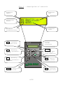
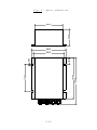
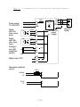
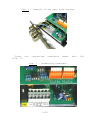
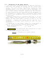
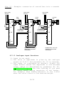
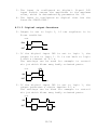
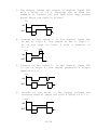
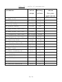
Karel Skipala Automation of production processes, modernization of machine control, production of industrial electronic devices http://www.skipala.cz USER MANUAL FOR DIGR-1500/E CONTROLLER Version: 1.3 August 2014 CONTENTS 1. Technical data.................................... 2. Description ...................................... 3. Connection ....................................... 4. Operating status ................................. 5. Activation ....................................... 6. R-run / S-stop ................................... 7. Setting and saving parameters .................... 8. Description of parameters ........................ 9. Maintenance ...................................... 10. Disposal ...................................... 11. Guarantee ..................................... 12. ES Declaration of conformity .................. 2/26 3 3 7 12 12 13 13 13 25 25 25 26 1. Technical data Power supply voltage Unap Maximum output current Output voltage Output frequency 2x digital input 1x digital output 1x analogue input Auxiliary output voltage Protection level Operational temperature Dissipated power Interference suppression Short circuit resistance Weight 110-230V 50/60Hz 4.5 A 5-100% Unap with 1% steps 20-100 Hz with 0.2 Hz steps 24V DC 24V DC max. 120 mA 0-10V DC 24V DC max. 150 mA 10V DC max. 10 mA IP54 10-55ºC 10 W EN 55011/A 1.5 kA 1.3 kg 2. Description The DIGR-1500/E controller is designed for control of vibration feeders driven with an electromagnetic coil. Two basic parameters, i.e. output voltage amplitude and frequency are controlled. The operation of the controller is defined with 18 different parameters that are set by the user from the control panel. Control of the controller is possible either from the control panel or using external analogue and digital signals. The controller is designated for installation outside of the switchboard. The controller includes also a safely separated 24V DC power supply for feeding sensors and for 10V DC power supply for analogue input feeding. Small size and effective user functions create prerequisites for deployment of these controllers operating both independently and together with a master control system in most feeder applications. 3/26 Fig. 1 – Description of controls Parameter number Parameter name Operational status Parameter value Parameter locked/unlocked Display 2 x 16 characters + - Increase displayed value stop ▲ - Browsing through parameters upward STOP RUN ▼ - Browsing through parameters downward /run – Switching over in S-stop or R-run condition enter - Saving the set values VIBRATORY FEEDER CONTROLLER - - Decrease displayed value on /off - Controller turning on/off 4/26 Fig. 2 – Basic dimensions 66,00 105,00 130,00 110,00 167,00 192,00 6,50 28,50 120,00 5/26 Fig. 3 - Connection of controller external parts T 8A Power supply 110-230V AC Digital input IN1 (max. stock level) Digital input IN2 (min. stock level) Analogue input AIN (amplitude control) U V PE L N PE PNP PNP 5k/N Digital output OUT Alternative amplitude control +24V S 0V 1 2 3 +24V S 0V 4 5 6 +24V 0V 7 8 9 +10V 10 11 12 560 560Ω 0-20mA 0V 8 9 0-10V 0V 8 9 6/26 Internal power supply Vibration feeder 3. Connection Connection of external electric components of the controller may be carried out only by the person with adequate electro-technical qualification. Connection may be done only if the controller is disconnected from the mains. Caution! Electric charge remains in capacitors after controller disconnection from the mains. This electric charge may become a cause of fatal injury! The lid may be removed only if the controlled has been disconnected from the mains for at least 2 minutes! 3.1. Installation The controller can be installed either in the horizontal position or in the vertical position with outlets facing downward. Caution! The controller should be mounted to a mechanically stable part of equipment free of direct vibrations. Drill four holes with a drill with diameter of 4.2 mm in the base plate to which the controller should be mounted and cut M5 threads in them. The pitch of the holes is apparent from Fig. 2. Mount the controller using 4 M5x8 screws with fan washers. Caution! Washers are needed so when tightened the layer of elox is cut and the controller is conductively joined to the body of the machine. 3.2. Lid disassembly Unscrew four M3 screws mounting the controller lid (Fig. 4) and remove the lid (Fig. 5). 7/26 Fig. 4 – Lid disassembly M3 M3 M3 M3 Fig. 5 – Lid removal To allow better access to the terminal block, we recommend dismounting also the part with outlets (Fig. 6). 8/26 Fig. 6 – Removal of the part with outlets There are (Fig. 7). connecting terminals under Fig. 7 – Connecting terminals 9/26 this lid 3.3. Connection of the power section The controller is provided with an internal T8A fuse. Capacitors are charged at turning and the current peak occurs. For that reason, preliminary protection with minimum value of 10 A and slow switching off characteristic of the D type should be selected; e.g. the circuit breaker LSN10D/1 supplied by OEZ Letohrad. If more controllers are connected to the equipment, it is necessary to connect them to different phase wires or ensure their sequential switching on, because of the current peak. Perform connection in accordance with Fig. 3. If the power supply cable delivered is not suitable for you, remove it and feed power voltage to the L, N, PE terminals. Connect the feeder coil to the PE, U, V terminals. A shielded cable should be used for this connection. Termination of the power cables is illustrated in Fig. 8. Select the wire section areas as follows: Wire cross section area 0.75 – 1.5 mm2 Cable diameter 8 - 10 mm Caution! The protective wire should be at least by 15 mm longer than the other wires. Fig. 8 - Termination of power cables 10/26 Fig. 9 – Connection of wires 3.4. Connection of the control section Wire cross section area 0.08 – 0.5 mm2 Cable diameter 3 - 6.5 mm Connect the sensors, digital and analogue signals as required by a specific application, in accordance with Fig. 3. Detailed explanation - please see Section 8.11.. The inputs and output are fed with safely separated voltage of 24V DC. 3.5. Lid reassembly After completing connection of the external parts of the controller, carry out reassembly of the part with grommets and top lid. Only then you can turn power supply on. 11/26 4. Operational condition Operational condition is shown on the display as the first symbol of the bottom line (Fig. 1). The controller can be in one of four statuses: S R W The controller is energized, however, all activities are turned off. STOP - The controller is turned on and it is in the S-stop condition. Output power voltage is blocked, the feeder is idle. Viewing and modifications of all parameters and saving the parameters in the memory is possible. RUN (operation)- The controller is turned on and it is in the R-run condition. Output voltage is connected and the feeder is vibrating. Viewing and modifications of all parameters are possible. WAIT - The controller is turned on and it is in the W-wait condition. Output power voltage is blocked, the feeder is idle. The controller waits for a signal from sensors or from a master control system. Viewing and modifications of all parameters are possible. 5. Turning on Controller turning on can be carried out using two methods: a) Turning on is to be carried out by depressing the button on/off . Turning off can be carried out by depressing the button again. This method of turning on is suitable in case that the controller operates independently without link to any other electric equipment. Caution! Internal circuits of the controller are still energized and for that reason, such turning off cannot be considered as safe disconnection from the mains! This condition is indicated on the display with the symbol . 12/26 b) Turning on is carried out automatically after power supply voltage connection. For this purpose, it is necessary to set the parameter No. 13 to 1 (see Section 8.13.). This method of turning on is suitable if controller power supply is connected through a connecting component (contactor) from a master electric device. 6. R-run / S-stop The controller is ready for operation after turning on. It is either in the R-run or W-wait condition in dependence upon setting of functions of digital inputs (parameter No. 11). The controller is switched over in the S-stop condition after depressing the stop/run button. When depressing the button again, the controller will be switched from the S-stop in R-run or W-wait condition. 7. Setting and saving of parameters Select the required parameter using the ▼ and ▲ buttons. If it has not been locked (key symbol), the value of parameter can be modified using the + or – keys. Saving the set parameters is possible only when the controller is in the S-stop condition (see Section 6.). Saving can be carried out by depressing the enter button. All parameters are saved together in the memory. 8. Description of parameters 8.1. Parameter No. 01 Amplitude The controller controls output voltage amplitude within the maximum range of 5-100% with 1% steps. The effective value of voltage depends on power supply voltage. Range of setting is restricted with the value of the parameter No. 05 Maximum amplitude and No. 06 Minimum amplitude. 8.2. Parameter No. 02 Frequency The controller controls output voltage frequency within the maximum range of 20-150 Hz with 0.2 Hz steps. Range of setting is restricted with the value of the parameter No. 07 Maximum frequency and No. 08 Minimum frequency. 13/26 Caution! When setting lower frequency than that for which the feeder coil has been designed – usually 50 Hz, growth of output current takes place. It is necessary to control this current in order to avoid coil overloading resulting in its burning. Output current should not exceed 1.2 multiple of nominal current of the feeder coil. 8.3. Parameter No. 03 Delay at switching over in the R-run condition If at least one sensor monitoring feeder output magazine filling (parameter No. 11) is not connected to the controller, we recommend setting the delay to the value of 0 s. If one or two sensors are connected, the delay has the following meaning: The controller is in the W-wait condition. If switching over from the W-wait condition in the R-run condition should take place on the basis of information received from sensors, it does not occur immediately but with a certain time delay. The setting range is 0-99 s. Use of the delay is explained using the following example: The feeder has filled the output magazine and is idle. Progressive withdrawal of components from the magazine takes place. Components are shifted in the magazine, which may result in a short interruption of the signal from the stock level sensor. If the delay would be set to 0 s, switching over in the R-run condition would occur in spite of the fact that the output magazine has not been emptied. The delay should be longer than the signal interruption time. This interruption will be ignored then and the controller will be switched over in the R-run mode only after real magazine emptying. 8.4. Parameter No. 04 Delay at switching over in the W-wait condition If at least one sensor monitoring feeder output magazine filling (parameter No. 11) is not connected to the controller, we recommend setting the delay to the value of 0 s. If one or two sensors are connected, the delay has the following meaning: The controller is in the R-run condition. If switching over from the R-run condition in the W-wait condition should take place on the basis of information 14/26 received from sensors, it does not occur immediately but with a certain time delay. The setting range is 0-99 s. Use of the delay is explained using the following example: the feeder is in the R-run condition and fills the output magazine. Individual components are passing the level sensor and create brief impulses. If the delay would be set to 0 s, switching over in the W-wait condition would occur in spite of the fact that the output magazine has not been filled up. The delay should be longer than the duration of the signal created with one component passing the level sensor. This interruption will be ignored then and the controller will be switched over in the W-wait condition only after real magazine filling up. 8.5. Parameter No. 05 Amplitude, maximum limit It is possible to limit setting of the maximum amplitude value in the parameter No. 01 using this parameter. 8.6. Parameter No. 06 Amplitude, minimum limit It is possible to limit setting of the minimum amplitude value in the parameter No. 01 using this parameter. 8.7. Parameter No. 07 Frequency, maximum limit It is possible to limit setting of the maximum frequency value in the parameter No. 02 using this parameter. 8.8. Parameter No. 08 Frequency, minimum limit It is possible to limit setting of the minimum frequency value in the parameter No. 02 using this parameter. A hint for you: If it is ascertained that the feeder operates optimally within a certain frequency and amplitude ranges, set the ascertained limitation using the parameters No. 05 - No. 08 and lock these parameters. The operator can then correct the amplitude and frequency values in the admissible range only without any more significant effect on correct operation of the feeder. 15/26 8.9. Parameter No. 09 Starting time It is desirable in some cases the feeder to be started and stopped smoothly. The value of amplitude at feeder starting and stopping is modified with this parameter. The range of setting of this value is 0-6 s. The time interval applies to starting from 0% to 100% and stopping from 100% to 0%. If e.g. the parameter No. 01 Amplitude is set to 50% and the parameter No. 09 Starting time is set to 4 s, amplitude will be increased continuously for 2 s during starting and also reduced continuously for 2 s during stopping. 8.10. Parameter No. 10 Current, maximum limit This parameter informs about the maximum output current with which the controller can be loaded. The value has been set by the manufacturer and cannot be modified. Caution! Exceeding this value may result in damage of the controller. 8.11. Parameter No. 11 Inputs and Output functions Utilization of the inputs and output is defined by setting of this parameter. The controller can use two digital inputs, one analogue input and one digital output according to requiurments of a specific application. For digital inputs use PNP type sensors. The digital output is supplied by safely separated 24V DC power supply. The output can be loaded by maximal current 120 mA. A hint for you: You can connect the digital output for example to a pneumatic valve, which controls air nozzles, switches or sheders. It can also be used as a signal for superior PLC control system, or as the signal when the controllers are connected into a cascade. Parameter No. 11 is divided into 3 separated numerals (Fig. 10). 16/26 Fig. 10 - parameter description No. 11 digital output function analogue input function digital input functions 8.11.1. Digital input functions 0- Digital inputs are not used. 1- The signal from the stock level sensor is connected to the digital input IN1. The sensor reacts to the presence of the pieces so that if a piece is present, the sensor output is 24V. If there is no piece present, output is 0V. The controller turns on and off with a delay that is given by the parameter no. 03 and no. 04. Input IN2 is not active. 2- Two sensors – for max. stock level and min. stock level – are connected to the digital inputs IN1 and IN2. Sensors reacts to the presence of the pieces so that if a piece is present, the sensor output is 24V. If there is no piece present, output is 0V. If the min. stock level sensor is not registering any pieces, the controller works. This will stop when both sensors register some pieces. The controller turns on and off with a delay that is given by the parameter no. 03 and no. 04. 3- The signal from the stock level sensor is connected to the digital input IN1. The sensor reacts to the presence of the pieces so that if a piece is present, the sensor output is 0V. If there is no piece present, output is 24V. The controller turns on and off with a delay that is given by the parameter no. 03 and no. 04. Input IN2 is not active. 17/26 A hint for you: Use this setting also in case when you control the feeder from a master PLC control system. Supply the START signal from PLC to the terminal No. 2 and supply common zero potential of the control voltage to the terminal No. 3. 4- Two sensors – max. stock level and min. stock level – are connected to the digital inputs IN1 and IN2. Sensors reacts to the presence of the pieces so that if a piece is present, the sensor output is 0V. If there is no piece present, output is 24V. If the min. stock level sensor not register pieces, the controller works. This will stop when both sensors register some pieces. The controller turns on and off with a delay that is given by the parameter no. 03 and no. 04. 5- Input IN1 behaves exactly the same as when the parameter in set to 1. In addition input IN2 is connected, which has the function START-STOP. This setting is used when connecting two or more controllers into a cascade (eg. Assembly of Fig. 11). The digital input IN1 is connected to the stock level sensor and input signal IN2 is connected to RUN from the previous controller in a cascade. If the input IN2 is 24V and input IN1 is 0V, the controller works. 6- Input IN1 behaves exactly the same as when the parameter in set to 3. In addition input IN2 is connected, which has the function START-STOP. This setting is used when connecting two or more controllers into a cascade (eg. Assembly of Fig. 11). The digital input IN1 is connected to the stock level sensor and input signal IN2 is connected to RUN from the previous controller in a cascade. If the input IN2 is 24V and input IN1 is 24V, the controller works. 18/26 Fig. 11 – Example: connection of controllers into a cascade Power supply 230V AC Power supply 230V AC Power supply 230V AC linear feeder U1 L N1 N PE PE START Signal 1 2 IN1 3 4 5 IN2 6 pre-stock tank circular feeder U1 L N1 N PE PE PNP stock sensor in linear feeder +24V S 0V 1 2 IN1 3 4 5 IN2 6 U1 L N1 N PE PE PNP +24V S 0V stock sensor in a circular feeder 1 2 IN1 3 4 5 IN2 6 7 8 9 7 8 9 7 8 9 10 11 OUT 12 10 11 OUT 12 10 11 OUT 12 Parameter No. 01 = 03 Parameter No. 01 = 05, or 06 (depending on the function of the sensor) Parameter No. 01 = 05, or 06 (depending on the function of the sensor) 8.11.2. Analogue input functions 0- Input is not used. 1- The value of amplitude is given by the analogue signal of 0-10 V. The parameter No. 01 is ignored. 2- The input is configured as digital. Signal 24V input switch causes the amplitude to the minimum value, which is determined by parameter No. 06. A hint for you: Use this setting if you need to reduce speed during operation of the feeder. For example, when adding material to the scales when the value closer to the desired weight. 19/26 3- The input is configured as digital. Signal 24V input switch causes the amplitude to the maximum value, which is determined by parameter No. 05. 4- The input is configured as digital that has the function START-STOP. 8.11.3. Digital output functions 0- Output is set to logic 1, if the regulator is in R-run condition. LEVEL RUN OUT T IME 1- If the digital input IN2 is set to logic 1, the output is set to logic 1. It is set back to logic 0 with a timeout of 0.3 s. The settings can be used for example to control air jet which blown away badly oriented parts. 0,3 s LE V E L IN2 OUT T IME 2- If the digital input IN2 is set to logic 1, the output generates a single impulse 0.5 s. The settings can be used for example to control air jet which blown away badly oriented parts. LE V E L IN2 OUT T IME 0,5s 0,5s 20/26 3- The output copies the status of digital input IN2 with a delay of 1.5 s. Settings can be used for example to control air jet that blow away excess parts after the tank is filled. LE V E L IN2 OUT T IME 1,5s 1,5s 4- Inverse to the value 1. If the digital input IN2 is set to logic 0, the output is set to logic 1. It is set back to logic 0 with a timeout of 0.3 s. 0,3 s LE V E L IN2 OUT T IME 5- Inverse to the value 2. If the digital input IN2 is set to logic 0, the output generates a single impulse 0.5 s. LE V E L IN2 OUT T IME 0,5s 0,5s 6- Inverse to the value 3. The output follows the inverted digital input IN2 with a delay of 1.5 s. LE V E L IN2 OUT T IME 1,5s 1,5s 21/26 7- The output is designed to control air valve, which closes the main air supply. The valve opens after the arrival of START signal and after 0.6 s the feeder starts. After stopping the feeder the air is closed with a delay of 1.2 s. LE V E L START OUT T IME RUN 0,6s 1,2s 8.12. Parameter No. 12 Wave type It defines the course of output voltage. Value 0: full sinusoid 1: half sinusoid, equivalent of unidirectional rectification 8.13. Parameter No. 13 After turning on It defines controller behaviour after power supply connection. Value 0: automatic turning on is blocked 1: controller automatic turning on is carried out after power supply voltage connection 8.14. Parameter No. 14 Language Language selection. Value 0: English 1: Czech * * Can be standardly ordered German eventually agreed an other language. or Russian, 8.15. Parameter No. 15 Password The locked parameter are unlocked by password entering. The password is defined from the factory as the three-position number 108 and cannot be modified. Its purpose is protection of the controller against accidental rewriting the locked parameters only. 22/26 8.16. Parameter No. 16 Locking Using this parameter, you can lock or unlock modification of individual parameters No. 01 - No. 14. Parameter No. 16 is always locked; for that reason, before modifying it, you have to enter the password (see the parameter No. 15). Then select the number of the parameter that you wish to lock or unlock using the + or – keys. Depress the button enter . The key symbol will appear behind the parameter number. It means that the selected parameter is locked. Unlocking is to be carried out using the same method. The key symbol disappears after depressing the button enter and the parameter is unlocked. 8.17. Parameter No. 17 Information If you wish to obtain more information on this product, please visit our website http://www.skipala.cz 8.18. Parameter No. 18 Service functions These features are intended for debugging vibratory feeder. 0- Service functions are disabled 1- Random stop. This function causes the controller to stop at a random time in the interval 10-120 s. Stopping time is 10 s. Function is used to simulate the operation of a vibratory feeder in real conditions. 8.19. Factory settings In case of any complications in controller operation, it is possible to carry out RESTART during which the factory settings of all parameters will be restored. RESTART is to be carried out as follows: disconnect the regulator from the power supply mains and wait for at least 2 minutes until capacitors are discharged depress the enter button and hold it depressed connect the controller to the mains release the button enter The values of parameters for factory listed in the table below (see Fig. 12). 23/26 settings are Fig. 12 – table of parameters parameter value factory range values values for your application 01 Amplitude 5-100% 33% 02 Frequency 20-100Hz 50Hz 03 R-run delay 0-99s 0s 04 W-wait delay 0-99s 0s 05 Amplitude, max.lim. 15-100% 100% 06 Amplitude, min.lim. 5-90% 5% 07 Frequency, max.lim. 24-100Hz 100Hz 08 Frequency, min.lim. 20-96Hz 20Hz 09 Starting time 0-6s 1.0s 10 Current, max.lim. 4.5A 4.5A 000-716 000 12 Wave type 0-1 0 13 After turning on 0-1 0 14 Language 0-1 0 11 In/Output functions 15 Password 16 Locking 000 all unlocked 17 Information 18 Service function 0-1 24/26 0 9. Maintenance The controller does not require any special maintenance. Only regular inspections in accordance with ČSN 33 2000-1 and ČSN 34 3100 standards and regulation No. 50/78 Coll. should be carried out. In the event of any defect, any repairs are forbidden and it is necessary to send the controller to the manufacturer for repair. A hint for you: In the case of complications with the operation of the controller, reset the factory setting of the parameters (Section 8.19.). 10. Disposal After expiration of service life of the controller, the controller should be handed over to a specialized company or to the manufacturer for professional disposal. 11. Guarantee The product is covered with the guarantee with the period of duration of 12 months from the date of sale. Serial number: Seller: Date of sale: 25/26 12. ES DECLARATION OF CONFORMITY In accordance with Act No. 22/97 Coll., Section 12, par. 3 letter a) on the technical requirements for products and on the change and amendment of some acts Manufacturer: Karel Skipala Rybník 162, 560 02 Česká Třebová Czech Republic Reg. No.: 48608017 http://www.skipala.cz Identification of the product: Name: Digital power controller Model: DIGR-1500/E We declare that the above-mentioned product fulfils the respective provisions of the following EU regulations: Government Directive No. 17/2003 Coll. (Directive of the European Parliament and the Council 2006/95/EC) Government Directive No. 616/2006 Sb. (Directive of the European Parliament and the Council 2004/108/EC) Description of the product: The product is designed for regulating vibration feeders driven by an electromagnetic coil. List of technical and harmonized standards used: ČSN EN 61010-1 ed.2:11, Article 5, 5.1, 5.1.2, 5.1.3, 5.1.4, 5.1.5.2, 5.1.7, 5.3, 5.4, 6, 6.1, 6.2.2, 6.4, 6.5.2, 6.5.2.3, 6.5.2.5, 6.5.3, 6.7, 6.9.2, 6.7.1.2, 6.7.1.3, 6.8.2, 6.8.4, 8.2, 8.2.1, 8.2.2, 8.3, 8.3.1, 10.5.2, 10.5.3; ČSN EN 60695-2-11:2001, ČSN EN 61000-6-2 ed.3:06, ČSN EN 61000-6-4 ed.2:07+A1:11 Source materials for issuing the EC Declaration of Conformity: Certificate No. 1120089 issued on 21.02.2012 by the Electro-technical testing institute, certified body No. 3018. The two last digits of the year in which the CE indication was attached to the product: 13 In Rybník dated 21.02.2012 26/26 Karel Skipala Company owner