1
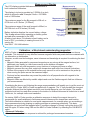
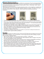
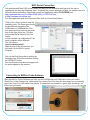
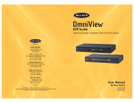
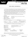
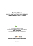
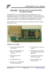
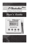
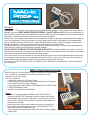
V5.0
Electronic Thickness Gauge
Disclaimer:
WARNING !! - This device uses extremely strong NEODYMIUM magnets. These magnets can cause injury or
damage if misused. KEEP AWAY FROM CHILDREN!!. DO NOT OPEN or USE if you have a pacemaker or
other medical condition that may be affected by magnetic fields. The strong magnetic fields can erase computer
hard drives, magnetic access and credit cards, Use at your own RISK.
MAG-ic Tech or its owners neither assumes nor accepts any liability for damages resulting from the handling or
use of this equipment. With your purchase, the buyer agrees that he/she is responsible for all damages and
injuries caused by the use of this product , which include personal injuries , property damages and any other
damage whatsoever. The buyer must agree with the terms before using the product.
Pay special attention when using this device to measure finished instruments. The probe tip is fabricated from
Delrin and may scratch or leave marks on finished surfaces.
DO NOT DRAG THE PROBE TIP OVER FINISHED SURFACES!! To avoid scratches and marks, you should
slightly lift the probe before moving it. A good method is to lift the tip and place a piece of soft cloth under before
moving and removing the cloth at the new measuring location.
Some users prefer to use a rice paper or other thin protective paper. You can also calibrate MAG-ic probe with
the rice paper inserted between the magnet and the probe. In this way the zero (0.00) value would include the
paper thickness and all measurements must be performed with the paper included.
You can also use the OFFSET function in the MAG-ic Probe Software to compensate for a thicker protective
cloth if required
MAG-ic Probe Device Overview
MAG-ic Probe V5.0 is the newest variation of the MAG-ic Probe product
line. It should be very intuitive to operate as all instructions are
displayed on the LCD display.
The device features Ÿ a connection socket for the Sensor Probe,
Ÿ a USB connection for external power and connection to a computer
for use with the MAG-ic Probe Software.
Ÿ a 3-position power switch (Battery OFF, Battery ON and INFO Mode)
Ÿ a Crisp LCD Display Screen
Ÿ Vent slots for temperature stabilization.
Notice
Ÿ Never turn the power switch ON OR connect to the USB of a
computer without FIRST attaching the sensor probe to the device.
Ÿ When attaching the Sensor Probe, please ensure that the sensor
plug is FULLY seated in the connector. a poorly inserted plug may
cause severe damage.
Ÿ Never remove the sensor probe whilst the device is powered ON
Ÿ Do not apply excessive pressure to the LCD window, the LCD is
fragile and should be treated with care.
Ÿ Try to minimize dust entering the device and store it in the supplied
shipping box.
USB
Connector
Probe Sensor
Socket
3
1-2-
3-Position
Power Switch
LCD
Display
Operating Instructions
3
1-2-
3-Position
Power Switch
Ÿ IMPORTANT! - First attach the Sensor Probe to the device BEFORE attempting to power ON or connect to a
computer via USB.
Ÿ MAG-ic Probe V5.0 is the only device that has been designed to operate either from the internal battery OR
from external power via a USB connection to a computer. This means you can save your battery for times
when you need to be completely mobile. When the device is attached to a computer, leave the POWER
SWITCH in the OFF position. (Position 1)
Ÿ If you are connecting to a computer via USB, leave the power switch in the OFF position and connect the USB
cable to the device and to a USB connector on your computer.
Ÿ If you intend to use battery power, move the Power switch to the ON position, (Position 2) which is the center
position and the device should turn ON.
Ÿ An information message is displayed on the LCD display for a few seconds.
Ÿ The device will display a message advising you to attach one of the 2 supplied magnets to the probe. Select
which magnet you will be using and attach it to the probe.
Ÿ The first stage of the calibration takes 5 seconds and the display reads “Please Wait” In this stage the device
is measuring the zero position.
Ÿ You will then be prompted to remove the magnet from the probe. Important - remove the magnet from the
probe and keep it at least 12 inches away from the probe
Ÿ After 5 seconds, the calibration is complete and the display will advise that either the BIG or SMALL magnet
was detected. Confirm this is the size you selected.
Ÿ The display will prompt you to replace the magnet on the probe and the display should read 0.00mm
Ÿ Test the operation by lifting the magnet slightly off the probe and the device should start to display some
measurement values.
Ÿ If you should exceed the measurement range of the selected magnet, the device will display an “Out of
Range” message.
Ÿ Your MAG-ic Probe is now calibrated and ready for measurement.
Ÿ NOTE - It is not critical that the display should read absolute zero (0.00). However, in this case, repeat the
above procedure by removing and restoring power to start the calibration again. If after the second calibration
the device still does not display 0.00 but is close (1 - 3mil), continue with your normal measurements.
Measurement Display
The LCD display provides thickness measurements in
both inches and millimeters.
Measurement in
1/1000th inch (mils)
The display in inches is provided as 1/1000th of an inch,
which is defined in mils. Example 53mils = 53/1000th
inch or 0.053inches
The maximum range for the Big magnet is 600 mil, or
6/10th inch or 0.6 inches. (15.24mm)
The maximum range of the small magnet is 420mil, or
42/100th inch or 0.42 inches (10.6mm)
Battery indication displays the current battery voltage.
This is only relevant when operating on battery power
and not when connected to the USB.
A battery level above 3V indicates a fresh battery and a
level of 2.5V, your battery is nearing the end of it’s
service life.
Use ONLY 1.5V AAA batteries.
Measurement in
milimeters (mm)
Battery Level
Display
(Only relevant
when powered
by battery)
Calibration - a Word about understanding magnetics
MAG-ic Probe uses magnets and magnetic sensors to measure the thickness of any non-ferrous
materials. This technique is very effective because magnetic fields can penetrate these materials with
no attenuation or deformation.
However, as with most technologies, some tolerance and knowledge is required for achieving the best
results.
Ÿ Magnetic fields generated by permanent magnets are very strong at the magnet surface, but
deteriorate very rapidly in a non-linear manner as the distance increases.
Ÿ Magnetic fields vary with temperature, even fractions of a degree will have an effect.
Ÿ Magnetic sensors also vary their output with temperature and suffer from internal fluctuations.
Ÿ Friction of the magnet on the material surface may cause it to not be centered on the probe tip
when moving the probe across the measured object.
Ÿ Dust and surface anomalies may cause the probe to be off perpendicular with regards to the
external magnet.
Ÿ Magnetic fields are affected by metallic objects and even the Earths magnetic field can influence
your measurements.
Considering the above, and following the usage recommendations will enable you to get the most out
of your MAG-ic Probe. MAG-ic Probe is supplied with 2 magnets. The ½” ball provides the strongest
magnetic field and thus the highest resolution, and should always be your first choice. The smaller
magnet should only be used when access to the inside of a finished instrument is limited due to small
f-holes etc, for example violins and mandolins.
On startup, MAG-ic Probe provides a calibration sequence to detect the magnet size and to
compensate for small variations in field measurement tolerances like temperature and location.
This initial calibration is suitable for most quick measurements, for example when you are making a
few measurements during shaping or sanding and then re-measuring periodically. This basic
calibration can and should be repeated often if conditions change, by simply turning the device OFF
and ON again, OR when using USB and the MAG-ic Probe Software, by selecting the CALIBRATE
option.
Advanced Calibration
a More advanced calibration sequence is advised for prolonged measurement sessions............
Advanced Calibration Continued.......
Temperature variation is the biggest enemy of electronic measurement. Even the heat generated by a
human hand will heat the probe enough to affect your measurements. However, the maximum effect
this would probably have on measurements is in the order of 0.1mm - 0.2mm (4mil - 8mil). If this is
important to you, please read on.......
When preparing for a more serious prolonged measuring session, such as mapping a complete top or
plate with many measurements, a two-step calibration sequence is advised. The goal of this 2-step
process is to only perform a final calibration, when the probe has reached peak operating
temperature.
Ÿ Power the device ON either with battery power or USB power and perform the initial calibration.
Ÿ Remove the magnet and hold the probe in your hand just as you would when doing measurements
on your object. Your fingers will transfer heat to the probe and after 3 - 5 minutes the probe internal
temperature should be equal to your finger temperature.
Ÿ Now perform the calibration sequence again by either turning the power switch OFF and ON if you
are using battery power OR if using the MAG-ic Probe Software by selecting the CALIBRATE
option. This calibration should be performed with the probe located above your instrument to be
measured in order to closely approximate the final working condition.
Ÿ Your MAG-ic Probe is ready for use.
Ÿ If temperature conditions change during the session or if you have to interrupt the session for a
prolonged period, repeat the above procedure.
INFO Mode
For reference purposes only, MAG-ic Probe includes an INFO Mode which will display the raw sensor
data on the LCD display. If you are interested, you can engage this mode while “heating” the probe
with your hand as described above.
Ÿ After the initial calibration, move the power switch to position 3 - INFO mode.
Ÿ After a short message, the raw sensor data value will be displayed. With no magnet on the probe,
this value will typically be around 31000-32500.
Ÿ You will notice that this value fluctuates considerably due to magnetic field instability and internal
electrical noise, but will generally have some median value, for example 32340.
Ÿ This raw sensor value is processed by the micro-processor in the MAG-ic Probe device and
passed through advanced algorithms to provide you the final measurement values.
Ÿ Whilst holding the probe in your fingers during the heating process and monitoring this raw sensor
value, you should notice that as the probe is heated by your fingers, the median value will start to
shift and will eventually stabilize, for example, a new median value may be 32220.
Ÿ At this time you can perform the final calibration as above.
USB Serial Connection
MAG-ic Probe V4 uses a common USB driver for communication with your computer. This driver
should be automatically installed by most Windows operating systems. When first connecting MAG-ic
probe to your computer USB port, be aware of on-screen messages to indicate if the driver has been
successfully installed. You may see a message as follows -
The COM PORT # is the information you need for the MAG-ic Probe Software. If you do not see the
above message, open the Control Panel and then click on Device Manager. In the Device Manager
window, click on the small triangle next to Ports (COM & LPT). This will list the ports currently installed
on your pc. Look for the USB Serial Port (COM #) and note the port number. If you double click this
line, you should see a similar properties window as below right.
In the above example, COM 3 is the port that will be used when we connect to the MAG-ic Probe
Software.
If a driver is not automatically installed.Please return to the www.magicprobe.net website and click
on Document and Driver Downloads.
Download the driver files for your operating system and also download the correct Driver Installation
Instruction Manual on this page.
Follow the instructions in the manual on how to get your driver working.
Once you have the driver properly installed, check back in your Device Manager and take note of the
COM PORT # so that you can use that # in the MAG-ic Probe Software.
MAC Serial Connection
One problem with Mac OSX is that it does not easily list the available serial ports to the user or
applications the way that Windows does. To identify the correct serial port in Mac, the easiest way is to
follow the below procedure. Download a small free application called COOLTERM from
http://download.cnet.com/CoolTerm/3000-2383_4- 10915190.html
or http://freeware.the-meiers.org/
Run this application and in the top menu Bar, click on Connection/Options
Click on the <Port> button to see the
available ports. The Serial port should
be identified as something like
USBmodem or USBSerial etc. Pick
this option and then click on the small
box to the right of this line. This box
will provide the full detail of the Port
Name.
In this example it is Usbmodem411 but
each computer will be different.
The full name is
/dev/cu.usbmodem411.
Make a note of this full name as you
will need it in the MAG-ic probe
Software.
You can test that the probe is working by
clicking on the OK button and then clicking
on CONNECT button.
You should see some data messages from
the probe appear in the window.
Connecting to MAG-ic Probe Software
Start the MAG-ic Probe Software and click on the PortSelection and Calibration menu and select
Serial Port. In the Settings box, either select the correct Com Port from the drop-down box or manually
type in the Com Port information from above. If connection is successful, a green light should turn on
in the top right corner.
/dev/cu.usbmodem411
Usage Tips
Correct
MAG-ic Probe is capable of measuring very small distances to 1/1000th inch. It
should make sense then that the probe should be absolutely square to the surface
being measured and the opposing magnet. If the probe is slightly tilted, the
distance from the center of the probe will be slightly farther from the magnet and
introduce false readings. It is a good idea to use the HOLD mode to ensure the
lowest reading by making small rocking and circling motions at each measuring
location.
Wrong
IMPORTANT. MAG-ic Probe makes approximately 100 measurements per second
but uses an advanced internal algorithm to average out the readings to ensure a
smoother display and more stable output. This is the reason that the change in
displayed values will seem to LAG behind rapid changes made between the probe
and magnet. Consequently it is important that you pause at every measuring
location to allow the output reading to stabilize. This should also be considered
when using the HOLD mode in the MAG-ic Probe Software.
Ÿ Turn OFF the unit when not in use to conserve battery life
Ÿ Take care of the magnets, they are fragile and will shatter or splinter if allowed to snap onto each
other or metal objects.
Ÿ Ensure your instrument does not contain any metallic objects to which the internal magnets can be
Ÿ
Ÿ
Ÿ
Ÿ
attracted. Removing a magnet from a finished instrument can be difficult.
Do not drag the probe across finished surfaces. Either lift the probe slightly from the surface before
moving to a new location, or insert a protective material under the probe before moving.
Use the larger magnet if possible. This will provide the highest resolution because of a stronger
magnetic field.
Only connect and remove the Probe connector when the unit is completely powered off. If this is
attempted while the unit is powered, damage may occur.
Avoid temperature changes after calibration.
Battery Replacement
Ÿ MAG-ic Probe V5.0 uses 2 x AAA 1.5V batteries.
Ÿ Slide the back over off to reveal batteries.
Ÿ Keep Power switch in OFF position(1) when not in use
or when connected to USB power.
Ÿ Battery indication on LCD display is valid ONLY when
using on battery power. Replace battery when battery
level reaches 2.5v.
Specifications
Measuring range (Large Magnet)
1 - 600mil (0-15mm)
(0-10mm High Resolution)
(Small Magnet)
0 - 420 mil (10.6mm)
Resolution
1mil (decreasing after 10mm)
Accuracy
3 mil - 0.1mm
Battery Voltage
Power Consumption
3VDC (2 x AAA)
10mA
Contact Info
We welcome any feedback and suggestions. If
you have any problems with your device please
contact us.
email - [email protected]
Phone (901) 212-6979