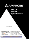
1
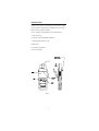
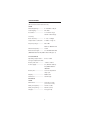
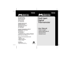
LH41A
Clamp On Ammeter
User Manual
•
•
•
•
•
Mode d’emploi
Bedienungshandbuch
Manual d’Uso
Manual de uso
Användarhandbok
LH41A
Users Manual
April 2007, Rev.2
©2007 Amprobe Test Tools.
All rights reserved. Printed in China
English
Clamp On Ammeter
Limited Warranty and Limitation of Liability
Your Amprobe product will be free from defects in material
and workmanship for 1 year from the date of purchase. This
warranty does not cover fuses, disposable batteries or damage
from accident, neglect, misuse, alteration, contamination, or
abnormal conditions of operation or handling. Resellers are not
authorized to extend any other warranty on Amprobe’s behalf.
To obtain service during the warranty period, return the product
with proof of purchase to an authorized Amprobe Test Tools
Service Center or to an Amprobe dealer or distributor. See Repair
Section for details. THIS WARRANTY IS YOUR ONLY REMEDY.
ALL OTHER WARRANTIES - WHETHER EXPRESS, IMPLIED OR
STAUTORY - INCLUDING IMPLIED WARRANTIES OF FITNESS FOR
A PARTICULAR PURPOSE OR MERCHANTABILITY, ARE HEREBY
DISCLAIMED. MANUFACTURER SHALL NOT BE LIABLE FOR ANY
SPECIAL, INDIRECT, INCIDENTAL OR CONSEQUENTIAL DAMAGES
OR LOSSES, ARISING FROM ANY CAUSE OR THEORY. Since some
states or countries do not allow the exclusion or limitation of an
implied warranty or of incidental or consequential damages, this
limitation of liability may not apply to you.
Repair
All test tools returned for warranty or non-warranty repair or for
calibration should be accompanied by the following: your name,
company’s name, address, telephone number, and proof of purchase.
Additionally, please include a brief description of the problem or the
service requested and include the test leads with the meter. Nonwarranty repair or replacement charges should be remitted in the
form of a check, a money order, credit card with expiration date, or a
purchase order made payable to Amprobe® Test Tools.
In-Warranty Repairs and Replacement – All Countries
Please read the warranty statement and check your battery
before requesting repair. During the warranty period any
defective test tool can be returned to your Amprobe® Test Tools
distributor for an exchange for the same or like product. Please
check the “Where to Buy” section on www.amprobe.com for a
list of distributors near you. Additionally, in the United States and
Canada In-Warranty repair and replacement units can also be sent
to a Amprobe® Test Tools Service Center (see address below).
Non-Warranty Repairs and Replacement – US and Canada
Non-warranty repairs in the United States and Canada should be
sent to a Amprobe® Test Tools Service Center. Call Amprobe®
Test Tools or inquire at your point of purchase for current repair
and replacement rates.
In USA
In Canada
Amprobe Test Tools
Amprobe Test Tools
Everett, WA 98203
Mississauga, ON L4Z 1X9
Tel: 877-AMPROBE (267-7623)
Tel: 905-890-7600
Non-Warranty Repairs and Replacement – Europe
European non-warranty units can be replaced by your Amprobe®
Test Tools distributor for a nominal charge. Please check the
“Where to Buy” section on www.amprobe.com for a list of
distributors near you.
European Correspondence Address*
Amprobe® Test Tools Europe
P.O. Box 1186
5602 BD Eindhoven
The Netherlands
*(Correspondence only – no repair or replacement available from
this address. European customers please contact your distributor.)
4
International Electrical Symbols
W
T
P
Caution! Refer to this manual before using the meter
Meter is protected by Reinforced or Double Insulation
Complies with EU directives
Indicates this equipment should for disposal be
n
seperated as Waste Electrical and Electrical Equipment
according to the EU directive 2002/96/EG
Indicates item is a Type A Current sensor and that
,
application around removal from HAZARDOUS LIVE
conductors is permissible
CONTENTS
Page
1 INTRODUCTION .............................................. 2
2 SPECIFICATIONS............................................... 3
2.1 Electrical Data .............................................. 3
2.2 General Data ................................................ 3
3 OPERATING INSTRUCTIONS ............................ 4
3.1 Switch On ..................................................... 4
3.2 Zero Adjustment .......................................... 4
3.3 Current Measurement ................................. 4
3.4 Data Hold ...................................................... 4
3.5 Auto Power Off ............................................. 4
4 SAFETY ............................................................. 5
5 BATTERY REPLACEMENT ................................. 6
6 WARRANTY ..................................................... 6
7 OTHER PRODUCTS .......................................... 7
1
INTRODUCTION
The LH41A current clamp meter has been designed for
reliable and accurate non-intrusive measurement of DC
and AC currents using advanced Hall Effect technology.
Measurement features include:
• Non - intrusive AC and DC current measurement
• 1mA resolution
• Average responding, RMS calibrated
• Autoranging/ Autozeroing
• Data Hold
• Low battery indicator
• Auto Power Off
AUTO ZERO
40A
OFF DC
HOLD
AC
LH 41A
Fig. 1
2
SPECIFICATIONS
2.1 Electrical Data
(All accuracies stated at 23°C ± 1°C)
LH41A
Measuring Range ..............
0 - 40 A DC or AC pk
Autoranging ......................
4A / 40A
Resolution ..........................
1 mA in 4 A range
10 mA in 40 A range
Accuracy
Basic Accuracy....................
± 1.3% + 5 digits
Temperature coefficient ...
± 0.05% of rdg / °C
Frequency range................
DC in DC
40 Hz to 400 Hz in AC
Overload capacity..............
150 A
Dielectric strength .............
3.7 kV RMS. 50 Hz 60s
(EN61010-2-032 Cat III, 300V Pollution Degree 2)
2.2 General Data
Operating temperature ....
0°C to + 50°C
Storage temperature with
Battery removed................
- 20°C to + 60°C
Power supply .....................
9 V, Alkaline battery
PP3, NEDA 1604 or
IEC6LR61
Battery life .........................
15 hours dependent
duty cycle
Display................................
4000 count
Characters ..........................
10 mm high
Mechanical
LH41A
Dimensions ........................
184 x 71 x 31 mm
(7.2 x 2.8 x 1.2 in.)
Max. jaw capacity ..............
19 mm ø cable
Max. jaw opening .............
20 mm (.78 in.)
Weight ...............................
235 g (1.2 Lb)
3
OPERATING INSTRUCTIONS
Refer to Fig. 1 for the main operating features of the
meter.
3.1 Switch On
Move the switch from the OFF / HOLD position to either
DC or AC to select the required mode of operation.
3.2 Zero Adjustment
When in DC mode the display zero may change due to
thermal shifts and other environmental conditions. An
auto zero adjustment is provided. Proceed as follows to
perform the adjustment:
• Ensure that the instrument is away from the current
carrying conductor and that the jaws are closed
during the adjustment cycle.
• Select the DC position of the power switch.
• Use the auto zero button to zero the display if
necessary.
The auto zero button can be used to null the effects of
the earth’s magnetic field on DC measurements.
3.3 Current Measurement
Select as required the DC or AC measurement option
using the power switch.
If necessary adjust the DC display to read zero as
described in section 3.2. Clamp the jaws of the instrument
around the conductor ensuring a good contact between
the closing faces of the jaws.
Observe and take measurements as required. Positive
output indicates that the current flow is in the direction
shown by the arrow on the instrument.
3.4 Data Hold
To activate the data hold, turn the power switch to the
OFF / HOLD position. The data will be held on the display
for approximately 10 seconds.
3.5 Auto Power Off
The meter will power down automatically after
approximately 8 minutes of inactivity.
4
SAFETY
This product conforms to the latest directives concerning
safety and electromagnetic compatibility.
• European Low Voltage Directives 73/23/EEC and 93/68/
EEC
• European EMC Directives 89/336/EEC and 93/68/EEC
Safety Standards
BSEN61010-1: 2001. General Requirements.
Safety requirements for electrical equipment for
measurement, control and laboratory use.
BSEN61010-2-032: 2002. Particular requirements for hand
held current clamps for electrical measurement and test.
EMC Standards
RF Susceptibility
EN50082-1: 1992 3V/m Residential, Commercial and Light
Industry
RF Emissions
EN50081-1: 1992 Residential, Commercial
and Light Industry
FCC Part 15 Class B
This product is designed to be safe under the following
conditions:
− indoor use
− altitude up to 2000m
− temperature 0°C to +50°C
− maximum relative humidity 80% for
temperatures up to 31°C decreasing linearly to
40% relative humidity at 50°C.
Use of the meter on uninsulated conductors is limited to
300V RMS or DC and frequencies below 1kHz.
This meter complies with the requirements of the above
safety standard for 300V Cat III Pollution degree 2
Safety in its use is the responsibility of the operator who
must be a suitably qualified or authorised person.
Users of this equipment and or their employees are
reminded that Health and Safety Legislation require
them to carry out valid risk assessments of all electrical
work so as to identify potential sources of electrical
danger and risk of electrical injury such as from
inadvertent short circuits.
5
Do not use the instrument if any part of it appears to
be damaged or if a malfunction of the instrument is
suspected.
When using the instrument ensure that your fingers are
behind the protective barrier see Fig. 1
Clean the case periodically by wiping it with a damp cloth
and detergent. Do not use abrasive cleaners or solvents.
Do not immerse the instrument in liquids.
BATTERY REPLACEMENT
SAFETY WARNING
Before removing the battery cover,
make sure that the instrument is
removed from any live electrical circuit.
When the Low Battery symbol is illuminated in the
display the minimum operating battery voltage has been
reached. Refer to Fig.1. and use the following procedure
to replace the battery.
Unclamp the meter from the conductor, turn it off using
the OFF / Hold power switch. Loosen the captive screw
which secures the battery cover. Lift the cover through
30° and pull it clear of the instrument body as shown in
Fig1. The battery is then accessible. Replace the battery
and re-fit the battery cover and fasten the screw.
Replacement with other than the specified type of
battery will invalidate the warranty. Fit only Type 9 V PP3,
Alkaline (MN1604 ).
6